Chapter 91
Technique
Managing Branches During Endovascular Aortic Aneurysm Repair
Mark Fillinger
The percentage of abdominal aortic aneurysms (AAAs) treated with endovascular repair has increased over time because data from randomized trials and national databases have indicated that open surgical repair has a three-fold higher 30-day mortality.1–5 A shift has occurred such that endovascular aneurysm repair (EVAR) accounts for the majority of AAA repairs in most large centers and in the United States as a whole, with a concomitant decrease in aneurysm-related mortality.6,7 Despite this fact, data indicate that during this same period, the aortic neck in less than half of men and one fourth of women with AAAs meets the anatomic criteria in the Instructions for Use (IFU) of commercial endografts, largely owing to inadequate length of the infrarenal aortic neck.8 Although newer endografts are able to treat shorter infrarenal aortic necks, it is clear that a substantial proportion of patients with AAAs require EVAR devices that involve the aortic branches. Similarly, thoracic endovascular aortic repair (TEVAR) has become the dominant form of repair for descending thoracic aortic aneurysms, leading to a recognized need for thoracic endovascular repairs extending into the aortic arch or visceral aortic branches.
Advanced Techniques for Managing Branches
Because of variations in patient anatomy, available technology, and surgeon preference, a number of different methods have been developed for managing aortic branches during endovascular aortic aneurysm repair. Conceptually these techniques are best described with standardized terminology and definitions that have been published in the Society for Vascular Surgery (SVS) reporting standards, which are used in this chapter.9
Aortic branch management can currently be divided into three major categories: de-branching procedures, parallel grafts, and branched-fenestrated devices.
Debranching Procedures
A hybrid endovascular/open debranching procedure is defined as a surgical bypass performed to originate perfusion of the aortic branch artery from a location that will not be covered by the intended aortic stent-graft (e.g., iliac-renal bypass, carotid-subclavian bypass) (Fig. 91-1). Debranching procedures are commonly performed for the aortic arch and visceral aortic branches, and less commonly for internal iliac artery branches.
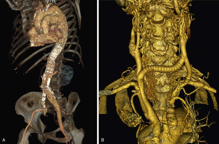
Figure 91-1 Examples of techniques for managing branches: hybrid debranching procedures. A, Hybrid debranching repair, type III thoracoabdominal aortic aneurysm with graft to visceral/renal branches from left iliac artery. B, Arch debranching with carotid-carotid bypass and carotid artery–subclavian artery transposition.
Parallel Stent-Grafts
Parallel stent-grafts (chimney, snorkel, periscope, sandwich grafts) provide inflow to the branch via a stent-graft placed alongside the aortic endograft, at least conceptually in a parallel fashion. In a “chimney” or “snorkel” stent-graft, the inflow segment is proximal to the branch that is covered by an aortic or iliac endograft. These devices originated when an aortic endograft was placed across the renal artery either intentionally or inadvertently during endovascular aortic aneurysm repair. If the renal artery is only partially covered, the stenosis can be corrected with a renal artery stent. If, however, the entire renal artery origin is covered, the resulting “bailout” stent or stent-graft has to extend far enough into the aorta that it begins to turn cephalad and become more parallel to the aorta. The resulting configuration was thought by some writers to look like a chimney because the stent protrudes above the aortic endograft (Figs. 91-2 and 91-3A). Others thought that configuration looked more like a snorkel, with the sharp curve into the renal artery as well as the portion sticking out above the aortic endograft. Both terms have been used interchangeably for this configuration.
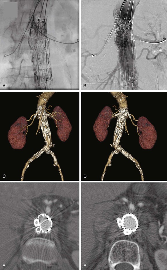
Figure 91-2 Bilateral renal artery “chimney” stent-grafts. A, Bilateral renal artery stent-grafts are in place and deployed; aortic stent-graft is in place and deployed covering the renal arteries (but not the superior mesenteric artery [SMA]); guide wires are still in place. B, Angiogram demonstrating renal artery patency, SMA patency, and no endoleak. C, Three-dimensional (3D) reconstruction viewing the anterior aspect. D, 3D reconstruction viewing the posterior aspect. E and F, Axial cross-sections showing the lack of compression of the chimney stent-grafts due to double thickness of stents in all but the most proximal location. Also note that the anatomy causes the chimney stent-grafts to be located preferentially on one side of the aorta rather than on opposite sides as typically shown in conceptual diagrams.
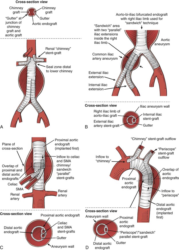
Figure 91-3 Parallel grafts: A, Renal artery “chimney” graft configuration. Ideally there should be a 5-mm or larger seal zone distal to the lowest branch in this configuration, to minimize the potential for endoleak via the “gutters” (shown on the “cross-section view” portion of the illustration). B, The chimney concept can be expanded to place the chimney graft (in this case an internal iliac stent-graft) within another endograft, which is often termed the “sandwich” technique. For the iliac aneurysm application, the length of the gutter for the sandwich portion should be as long as possible to minimize the chance of endoleak, but this is rarely more than 5 cm. C, The sandwich technique can be applied to a thoracoabdominal aortic aneurysm. This diagram illustrates chimney/sandwich grafts to the visceral arteries in a thoracoabdominal repair in which the thoracic endograft ends proximal to the celiac artery origin, and chimney stent-grafts from the celiac and superior mesenteric artery (SMA) are brought up inside the proximal thoracic endograft, then an overlapping aortic graft covers the branch origins and chimney grafts to create the “sandwich.” Much longer gutters are required because there is no aortic seal zone distal to the gutters. The consequences of endoleak are high for this application, so the gutter length for the sandwich portion should be at least 5 cm and preferably more than 8 cm. D, The chimney technique has been applied to the arch vessels, although motion and stroke risk are higher in this application (see text). In this illustration, the “chimney” can be relatively short owing to the seal zone distal to the carotid artery origin. There is no seal zone distal to the subclavian in this case, so the “periscope” and “sandwich” techniques can be used in this area to preserve the subclavian artery flow. Similar to the thoracoabdominal application, the gutter length for the overlap “sandwich” portion distal to the left subclavian should be more than 8 cm. In most cases a carotid artery–subclavian artery bypass or subclavian transposition is preferred.
After early success with these bailout maneuvers, some interventionists began to use them as planned repairs for unusual cases with high rupture risk and no good open repair options. Eventually the concept was extended to the internal iliac artery,5 also during endovascular aneurysm repair (Fig. 91-3B). In this location the reason to use the chimney graft was to preserve the internal iliac artery in patients with common iliac artery aneurysms. In these cases the “chimney” portion cannot extend into a normal vessel, because none exists. Thus the chimney has to extend into the iliac limb of an aortic endograft, creating a “sandwich” with the iliac limb encasing the internal iliac chimney stent-graft and an iliac stent-graft extension extending from the common iliac artery into the external iliac artery. These concepts have been enlarged to include a “periscope” stent-graft, in which inflow goes to the branch distal to the origin of the branch being covered (see Fig. 91-3C). Currently, “sandwich” configurations can involve any combination of chimney or periscope-type stent-grafts, with locations at the aortic arch or visceral aortic segment, but all derive their name from being “sandwiched” inside an endograft rather than resting inside a native artery (see Figs. 91-3C and D). In order to simplify discussions of these configurations, the term “parallel” graft or stent-graft was coined, because they all have the common theme of at least conceptually bending to become parallel to the inflow artery (aorta or iliac). We preferentially use the term stent-graft here rather than graft, because the branch portion of the repair may comprise stents, stent-grafts, or combinations. Despite the complexity of the concept, the final outcome of these procedures can be good with appropriate patient selection, proper planning, and good technique (Fig. 91-4).
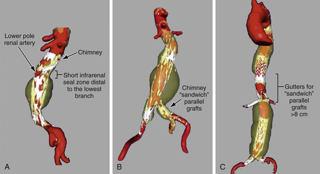
Figure 91-4 Three-dimensional reconstructions of aneurysms treated with parallel grafts. A, “Chimney” stent-graft to a lower pole left renal artery, with a 5-mm aortic seal zone distal to the most distal gutter. B, Endovascular abdominal aortic aneurysm repair including bilateral common iliac artery aneurysms, treated on each side with chimney/sandwich technique and stent-grafts to the internal iliac arteries. C, Chimney/sandwich stent-grafts to the visceral arteries in a thoracoabdominal repair in which the thoracic graft stops short of the celiac, parallel branch grafts are brought up inside the thoracic graft, and then an overlapping aortic graft covers the branch origins and branch grafts to create the “sandwich.”
Branched-Fenestrated Repairs
The branched-fenestrated device category includes a number of aortic graft modifications that may be custom-made by a manufacturer or by a physician. These modifications to aortic endografts are scallop, fenestration, stented fenestration, fenestrated branch, and side-arm branch (Fig. 91-5).
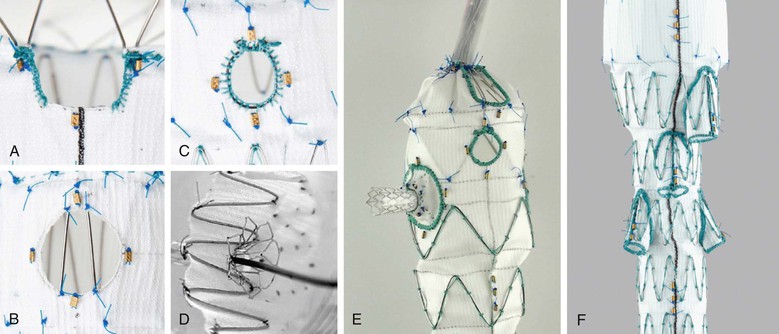
Figure 91-5 Illustrations of (A) scallop, (B) fenestration, (C) reinforced fenestration which is more suitable for stenting or fenestrated branches. D, Stented fenestration, (E) fenestrated branch, and (F) side-arm branch, as defined by the SVS TEVAR Reporting Standards.
As defined in the SVS TEVAR reporting standards,9 scallop refers to a portion of aortic graft material removed to accommodate an aortic branch at the proximal or distal end of the aortic repair, thus allowing some fabric to extend further proximally or distally than a simple cylindrical configuration would allow. Fenestration or fenestrated may be used to indicate the presence of openings purposely created within the endograft to allow perfusion of visceral or brachiocephalic arteries in the region otherwise covered by the aortic endograft. If stents are placed within fenestrations, they should be described as stented fenestrations. If a stent-graft is placed within a fenestration but is not required for sealing, the proper term would still be stented fenestration, because the implication is that a seal can be obtained between the aortic endograft and the aortic wall immediately surrounding the fenestration. Branched is used to indicate the presence of a stent-graft intended to connect and seal the primary aortic endograft to visceral or brachiocephalic arteries in the region otherwise covered by the aortic endograft. The implication is that a stent-graft branch is required for sealing between the primary aortic endograft and the target visceral or arch vessel (i.e., a fenestration or stented fenestration in the same location would allow flow or pressurization of the aneurysm sac). A fenestrated branch seals into a fenestration of the aortic endograft that has been reinforced to allow sealing, and side-arm branch implies that a side arm has been sewn onto the aortic stent graft component to allow sealing, typically in cases in which the gap between the aortic endograft and the branch is large. The branch can be oriented antegrade or retrograde. Devices often have a combination of these features. For example, the commercially available “Z-fen” device (Zenith Fenestrated AAA Endovascular Graft, Cook Medical, Inc., Bloomington, Ind) is custom-modified by the manufacturer and typically has a combination of fenestrations and a scallop (Fig. 91-6).
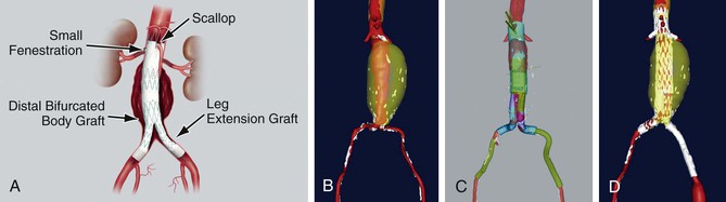
Figure 91-6 The commercially available Zenith Fenestrated AAA Endovascular Graft (“Z-fen”) (Cook Medical, Inc., Bloomington, Ind) is custom-modified by the manufacturer and typically has a combination of fenestrations and a scallop. A, The device. B, Abdominal aortic aneurysm prior to repair. C, Virtual graft (M2S, West Lebanon, NH) plan for Z-fen repair. D, Postoperative three-dimensional reconstruction from CTA.
Manufacturers have now started to create “off-the-shelf” devices, which may incorporate any number of aortic graft modifications in a single device, but in a standard configuration (Figs. 91-7 and 91-8). The standard-configuration devices have restrictions in terms of the range of anatomy that they can be used to treat but have the potential advantages of being available in on-site inventory for emergency use, reducing device costs, and simplifying procedure planning.
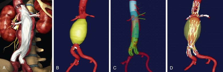
Figure 91-7 The “off-the-shelf” Ventana Fenestrated Stent Graft System (Endologix, Inc., Irvine, California), which is currently in clinical trials. A, Illustration of the device. B, abdominal aortic aneurysm prior to repair. C, Virtual graft(M2S, West Lebanon, New Hampshire) plan for Ventana repair with the proximal portion in transparent blue, the scalloped portion in lighter blue, and the standard AFX infrarenal portion of the graft in green. D, Postoperative three-dimensional reconstruction from CTA.
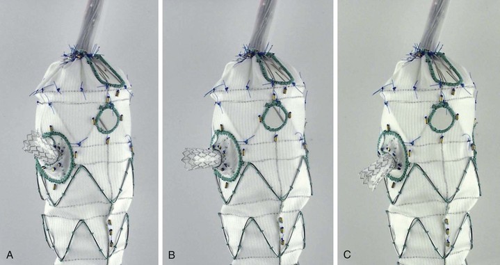
Figure 91-8 The “off-the-shelf Zenith Pararenal Endovascular Graft (Cook Medical, Inc., Bloomington, Ind), currently known as “p-Branch,” has a standard configuration consisting of a celiac scallop, a superior mesenteric artery fenestration, and “directional” fenestrations to accommodate most renal arteries with fenestrated branches. A, B, and C all illustrate the same stent-graft branch, capable of moving in three different directions while still attached to a flexible “directional” reinforced fenestration.
Device Selection
For patients who require endovascular aneurysm repair encompassing major aortic branches, the first choice should be a commercially available device that has been evaluated in clinical trials. The availability of commercial devices is relatively good outside the United States and constantly improving in all parts of the world. In the United States, there is currently only one commercially available custom-modified fenestrated device for juxtarenal AAAs, the Z-fen, and a clinical trial is in progress for an off-the-shelf branched-fenestrated device for juxtarenal AAAs (Ventana Fenestrated Stent Graft System, Endologix, Inc., Irvine, Calif; see Fig. 91-7). Manufactured devices are commercially available for thoracoabdominal and thoracic arch aortic aneurysms in other parts of the world, and U.S. clinical trials for these devices are on the horizon (see Chapter 137). Iliac branched devices are also in clinical trials (also discussed in Chapter 137).
If a commercially produced branched-fenestrated device is not available for the anatomy involved, the decision-making process becomes more difficult. Options include a variety of “off-label” (not listed in a product’s Indications for Use) options, such as physician-modified branched-fenestrated devices, in situ fenestration, parallel stent-graft snorkel/chimney/periscope/sandwich procedures (see Fig. 91-3), and hybrid endovascular/open debranching procedures (see Fig. 91-1). One might consider hybrid debranching procedures to be “on-label,” but by definition the aortic device in these cases is being implanted in a location and/or manner that was never studied in clinical trials; thus there is no more evidence for these procedures than for the others. For example, the aortic arch has a very different degree of radial, lateral, and rotational motion from the descending thoracic aorta, and implants in the former location have not been studied for most devices.10 The “open” portion of the procedure must also be taken into account as part of the risk, and this issue also has never been part of a clinical trial. Parallel snorkel/chimney/periscope/sandwich stent-grafts involve putting the branches in a compressed environment for which they were not designed or tested. Physician-modified devices also represent “off-label” use and require an Investigational Device Exemption (IDE) in the United States.11,12 Many commercial devices that manage aortic branches during endovascular repair are being evaluated and will facilitate future repair. Until then, physicians need to be aware of the regulatory environment in their countries when considering off-label use or modification of existing devices to optimally manage patients.
Procedure Planning
Imaging
Standard procedure planning should involve advanced three-dimensional (3D) reconstruction techniques based on computed tomography angiography (CTA) or magnetic resonance angiography (MRA). Because magnetic resonance angiography has half the resolution of CTA and does not demonstrate calcifications well,13 CTA is the cross-sectional imaging method of choice. Cross-sectional images are ideally obtained with “thin cuts” of 1 mm or less thickness for complex interventions involving the branches. Most regional hospitals now have capabilities to perform imaging at this level of detail if it is specified and communicated to the radiologist.
Once the cross-sectional imaging is acquired, any number of three-dimensional (3D) imaging platforms (e.g., from 3Mensio Medical Imaging BV, Bilthoven, The Netherlands; M2S, Inc., West Lebanon, NH; TeraRecon, Inc., Foster City, Calif; Vital Images, Inc., Minnetonka, Minn) can be used for computer-aided measurement, planning and simulation (CAMPS). No matter what platform is used, it is highly preferred for the person performing the implantation to also perform the measurement and planning. This arrangement leads to greater insight about the short- and long-term risks of the procedure, issues requiring heightened awareness during the procedure (e.g., device tilting near a branch), and potentially advantageous alternatives (e.g., simply altering the side of insertion for the main device). Thorough knowledge of the patient’s vascular anatomy, not simply knowledge of the anatomy to be treated, is essential. For example, exophytic aortic plaque in the aorta near the tip of the guide wire may be a risk for embolization. Plaque near the tip of the delivery system may be located on the patient’s right or left, making access on the opposite side (so the iliac anatomy pushes the delivery system tip away from the plaque) preferable. The decision regarding whether to occlude an internal iliac artery may not seem critical in a typical patient with an aneurysm. However, in a patient with a juxtarenal AAA and a small thoracic aneurysm, preservation of an internal iliac artery at the first procedure may lower the paraplegia risk of a subsequent procedure.
Preprocedure planning should include details such as the location of branch artery origins with respect to bony landmarks and the C-arm gantry angles that display the branches “end-on” or at right angles. For the superior mesenteric artery (SMA) and sometimes the celiac artery, the surgeon should know the angle that will place the SMA (and its fenestration or branch) in the apparent “center” of the aorta. For systems that allow 3D “fusion” of intraoperative or preoperative CT scans, these latter details are being incorporated into the procedure when the CT and 3D reconstruction are “registered” to the patient, but the primary advantages of such a system can be obtained using detailed planning on a 3D platform preoperatively without the expense of the “fusion” systems. Because the anatomy will be distorted by the stiff guide wire and delivery system, focal confirmatory arteriograms using small amounts of contrast agent are typically necessary with either method. Another major issue that is common to planning of complex cases is determining whether or not a spinal drain should be inserted (see Chapter 136).
Commercial Device Planning
For the physician planning a branched-fenestrated repair incorporating a specific commercial device, the manufacturer typically has an instructional slide set and a step-by-step procedure planning form. For example, the form for the Z-fen device is two pages long, progressing from basic measurements of distances between branch origins and cross-sectional branch angles through the locations of device scallops and fenestrations, to the part numbers for the components that will be used for the repair, including the proximal component that will have the custom modifications. Endologix has a similar step-by-step approach for the Ventana device that results in a part number for the device. Any commercial application of branched-fenestrated endografts is likely to require a training course for planning, and a certain number of cases are subject to secondary review before a physician is given approval to independently size and order devices. Initial implantation procedures are also proctored so the physician can learn the implications of device selection on the procedure itself.
Noncommercial Device Planning
Debranching Procedures
The simplest procedure planning is for hybrid debranching procedures (see Fig. 91-1), in which the device implantation is planned in the standard fashion for EVAR or TEVAR (see Chapter 136), without regard for the presence of branches. The location of the device may differ from standard, but the planning in terms of access, oversizing, and deployment are similar. Data suggest that devices implanted in the aortic arch should have greater oversizing than devices implanted in the descending thoracic aorta, because of greater radial excursion in the ascending aorta and arch.10,14 The optimal extent of oversizing for the aortic arch is unknown at present, however. Procedure planning for the aortic graft associated with in situ branches is again similar to standard, with the exception of planning the diameter and length of the branch stent-graft, placed in the left subclavian artery in the vast majority of in situ cases.15,16 The open portion of the procedure is planned in standard fashion for the proposed bypass.
Parallel Grafts
Procedure planning is slightly more difficult for parallel grafts, in large part because there is a paucity of data regarding outcomes related to branch length, type, and compression. The following are general guidelines. Seal zone is defined as the area where the endograft is expected to seal, and is typically described by its length. For a snorkel/chimney procedure, ideally there will be at least a 5-mm seal zone distal to the most distal branch, which is typically distal to the renal arteries for EVAR (see Figs. 91-3A and 91-4A) or distal to the left subclavian artery for TEVAR with a left subclavian artery chimney (Fig. 91-9). For a periscope procedure, there should be a similar seal zone proximal to the most proximal branch.17 For snorkel/chimney/periscope-type procedures without such a seal zone, and by definition all “sandwich” procedures, the “gutters” adjacent to the branch stents or stent-grafts are potential pathways for endoleak into the aneurysm sac. Planning to minimize this problem involves creating very long parallel grafts in the aorta so that the gutters are more likely to become thrombosed (see Figs. 91-3 and 91-4). Most suggest that the length of the gutters must be at least 5 cm for aortic parallel graft branches when a “sandwich” technique is used in the visceral aorta, and 8 cm if the parallel branches are in the arch.18 An overlap of 5 cm for the gutters is even desirable for internal iliac chimney grafts, although techniques with 4-cm overlap have good early results.18–20
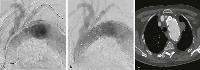
Figure 91-9 Thoracic endovascular aortic repair (TEVAR) with left subclavian artery chimney stent-graft. A, The brachial artery is typically used for the subclavian stent-graft access in this case, so the same access is often convenient for “road-map” angiography. Note the short seal zone distal to the subclavian artery for sealing distal to the gutters of the chimney. The aortic endograft is nearby to minimize the time between establishing the road map and final deployment of the graft. B, Angiogram following deployment of the aortic and subclavian artery stent-grafts. Typically two coaxial stent-grafts are deployed because of the concerns for durability in this location, and in this case, a second aortic endograft was placed just distal to the subclavian to enhance sealing, with no endoleak at completion. C, CT scan showing the cross-section of the chimney stent-grafts (double thickness) and the aortic endograft, which is displaced but still sealing proximal to the aneurysm without crushing the chimney.
The other common theme for parallel grafts is the issue of how to size or oversize the endografts to best accommodate the parallel branch grafts. Predicting the degree to which the aortic endograft will conform to minimize the gutters is not simple, because of constraining anatomy or multiple parallel grafts (see Fig. 91-2), the need to reinforce the parallel graft to prevent it from being crushed or from fracturing as a result of fatigue (see Fig. 91-9), and differences in aortic and branch diameters (compare Fig. 91-9C with Fig. 91-10B). Most writers suggest sizing the endograft in the aorta normally (7%-25% oversizing is typical per manufacturer’s Instruction for Use), allowing adequate circumference for the graft to invaginate into the gutters to an extent. Some writers suggest that the circumference of the aortic graft should be even larger than normal, however, to allow it to conform around the parallel graft, although large grafts may be too stiff to do this.21 Studies in flow phantoms and CT phantoms indicates that the degree of aortic graft oversizing matters, but branch size also affects aortic compression, branch graft compression, and gutter size.22,23 The optimal aortic and branch graft sizes may depend on the location and the stent-grafts used for the repair.22,23 For internal iliac parallel grafts (called sandwich, chimney, and double-barrel technique by various writers), the iliac limb of the aortoiliac stent-graft commonly has a 16-mm iliac diameter, with the external and internal iliac branches inserted within it. Most physicians use an external iliac stent-graft that has the same proximal diameter as the aortoiliac device limb diameter (16 mm) and an internal iliac “parallel graft” sized to the internal iliac artery (Fig. 91-11), although some use a more symmetrical diameter for the branches with similar results.18–20 The type of stent-graft used for these procedures is also part of planning and is discussed in the later section on technique.
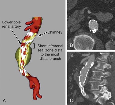
Figure 91-10 Single–chimney stent-graft to a lower pole renal artery. A, Three-dimensional reconstruction of a chimney stent-graft to a lower pole renal artery, with a 5-mm aortic seal zone distal to the most distal gutter. B, Axial CT cross-section demonstrating minimal “gutter” space between the chimney stent-graft and the aortic endograft. C, Sagittal CT cross-section showing the chimney stent-graft extending proximal to the aortic endograft with the classic “chimney” appearance.
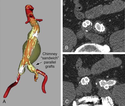
Figure 91-11 Internal iliac artery chimney/sandwich parallel stent-grafts: A, Three-dimensional reconstruction showing the abdominal aortic aneurysm and bilateral common iliac aneurysms in transparent yellow, contrast-enhanced blood flow in red, and metallic stents in white. B, Axial CT cross-section demonstrating minimal “gutter” space between the chimney stent-graft, the external iliac stent-graft extension, and the iliac limb of the aortic endograft on each side. Note that the right side uses a technique with similar-size internal and external iliac artery limbs, and the left uses a larger cross-section for the iliac extension. They differ because the left side was used for an endoconduit with an EXCLUDER limb (W.L. Gore & Associates, Inc., Newark, Del) with a 16-mm proximal diameter tapering to a 12-mm diameter distally, whereas on the right a 13-mm VIABAHN endoprosthesis (W.L. Gore & Associates) was used for the external iliac artery and a 10-mm iCAST stent (Atrium Medical Corporation, Hudson, NH) for the internal iliac artery. On both sides, the iCAST stent was reinforced with a self-expanding uncovered stent. C, Axial CT cross-section demonstrating the devices conforming at a more distal site as well as the lack of endoleak.
Physician-Modified Grafts
The planning techniques for physician-modified branched-fenestrated endografts are almost identical to those for commercial devices, because the modifications made by surgeons are essentially the same as those made by the manufacturers of commercial custom-made devices (see “Techniques”). The basic concept is that, like commercial devices, the branched-fenestrated endograft has either fenestrations or reinforced fenestrations or side-arm branches (see Fig. 91-5).9 Because physician-modified devices do not have standard measurement forms or manufacturer support staff, planning requires a much more detailed knowledge of the devices and their deployment mechanisms.
Side-Arm Branches
Side-arm branches are easier to plan than fenestrated branches because they require only placement at an adequate distance from the branch origin to allow cannulation of the arterial branch, combined with a reasonable approximation of the arterial branch angle on the cross-sectional “clock face.”24,25 Side-arm branches still have several planning issues, however. They require an adequate aortic lumen in order to open properly, and adequate space is often not available. One must take into account whether the device will be pushed eccentrically in the aorta, thereby compressing a branch. The placement of branches proximally also typically requires more aortic coverage than placement of fenestrated branches, thereby increasing paraplegia risk to some degree. This latter issue is not a problem in typical type I, II, or III thoracoabdominal aortic aneurysms, but it is an issue for type IV thoracoabdominal aortic aneurysms and for juxtarenal aortic aneurysms. Lastly, side-arm branches are more difficult and time-consuming to construct than reinforced fenestrations for fenestrated branches. Side-arm branches are currently unavailable on devices in the United States.
Fenestrations
Fenestrations and fenestrated branches are the only option for devices in the United States and are much more common in physician-modified devices as well, owing to the difficulty of constructing side-arm branches. Although fenestrations and fenestrated branches are easier to construct and minimize the amount of aortic coverage, they require the most precision in planning. If a side-arm branch is 5 to 10 mm too high or 15 degrees off the true branch “clock face” angle, it will likely still function quite well. If a fenestration is malpositioned in similar fashion, the arterial branch will be difficult or impossible to cannulate, likely resulting in an occlusion.
Measurement Details
Readers are directed to educational efforts by the various manufacturers with regard to procedure planning for fenestrations, fenestrated branches, and side-arm branches, which are available on the Internet and at large vascular meetings worldwide. Three important planning issues should be noted, however. First, a common misconception is that planning the location of a fenestration or branch requires only the distance from the graft edge and the “clock angle” to denote the location; this is untrue, as shown on standard commercial device measurement forms and in Figure 91-12. Proper measurement placement of the fenestration on the device requires knowledge of the aortic lumen diameter at the site of the branch, which can differ significantly from the diameter of the branched-fenestrated aortic graft itself. The location of the fenestration or branch opening should be designated with use of both the lumen diameter and the angle relative to a predetermined reference point (anterior on the patient or relative to another branch) to calculate an arc length.
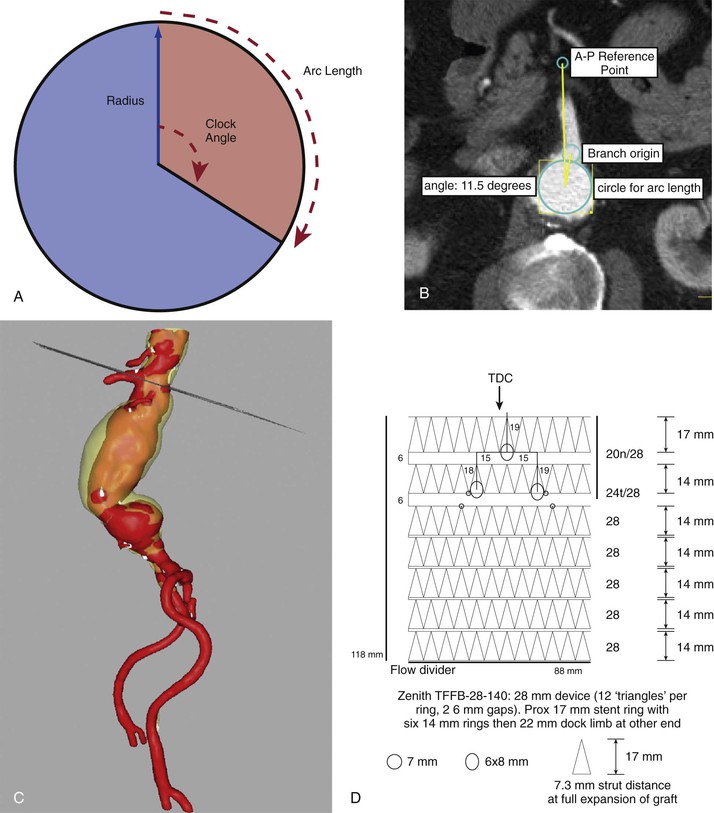
Figure 91-12 Branch origin measurements. A, “Clock face angle” as defined by commercial endograft measurement methods (the reference point can be an anterior-posterior [AP] line AP or a specific branch). B, Illustrating the use of lumen diameter for arc length. C, The plane of the measurement dropped into a three-dimensional reconstruction for context. D, The transformation of measurements onto a scale drawing of a potential device. TDC, Top Dead Center.
For example, a 90-degree clock angle on a 24-mm graft is an arc length of (angle × π × diameter) divided by 360, as follows:

The same 90-degree clock angle on a 30-mm graft is an arc length of:

This is a common scenario, with a 30-mm graft diameter required for adequate oversizing to obtain proximal seal/fixation, but only a 24-mm lumen available at the renal artery origin. The 5-mm difference in these two fenestration locations (calculated by equations above) could easily mean the difference between a properly aligned fenestration and a branch occlusion. Converting the clock angle and lumen diameter into a calculated arc length on the graft is done by the manufacturer using form templates or by the surgeon using computer-aided design and/or scale drawings or similar technique (Fig. 91-13).
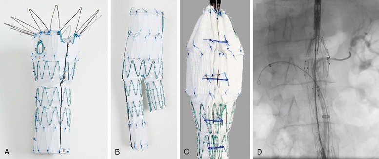
Figure 91-13 Components of the Zenith Fenestrated AAA Endovascular Graft (Z-fen) (Cook Medical, Inc., Bloomington, Ind) (Z-fen). A, Proximal device containing a scallop and fenestration. B, Distal device that seals into the fenestrated device and allows completion of the repair similar to that for the nonfenestrated Zenith device. C, Posterior location of diameter-reducing ties for the proximal device. These temporary constraining ties aid in cannulating the renal arteries, as shown in D.
Stay updated, free articles. Join our Telegram channel

Full access? Get Clinical Tree


