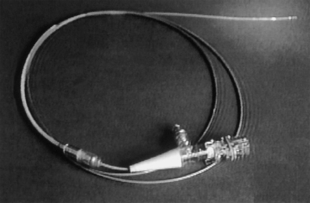
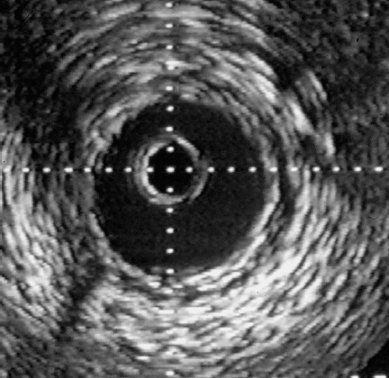
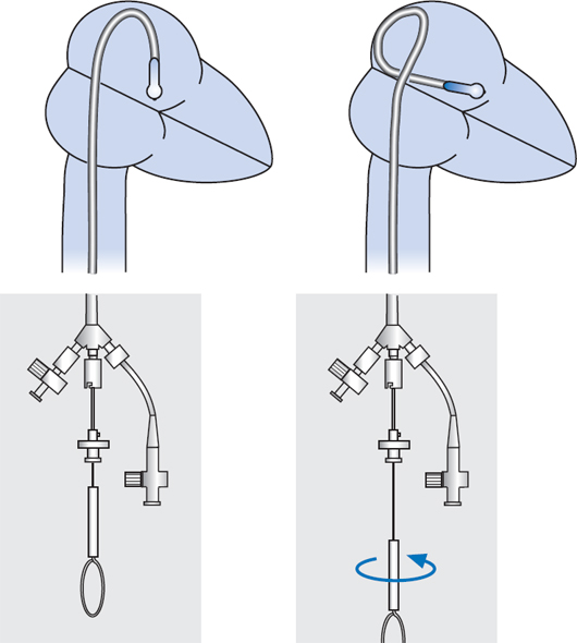
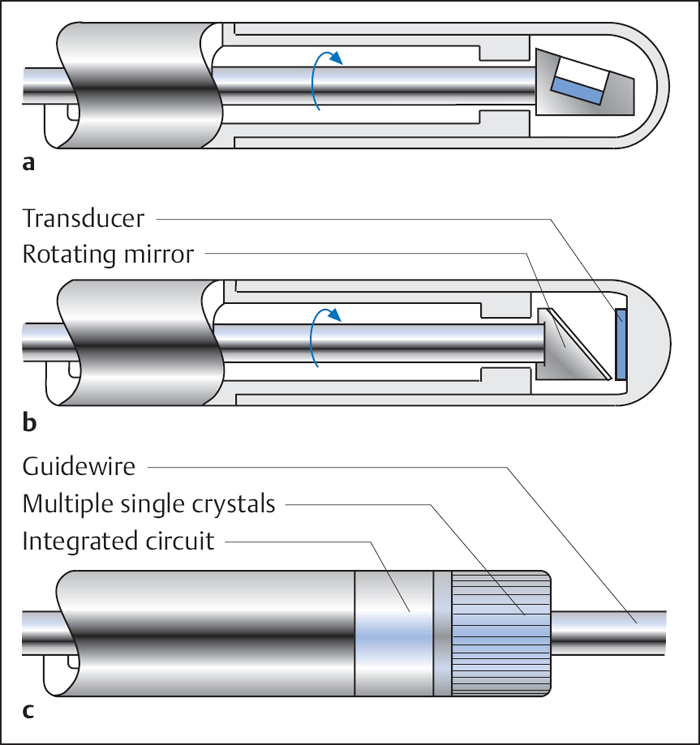
29 Special Examination Techniques Intravascular ultrasound (IVUS) allows not only imaging of the vessel lumen but also the morphological evaluation of the vessel wall and the structure of an atheroma. One of the reasons for its development was the necessity to evaluate the effects of different interventional modalities (balloon angioplasty, directional atherectomy, rotational atherectomy, stenting) on the stenosis and vessel morphology. In addition, the technique can inform basic and clinical science about different aspects of CAD such as plaque development, plaque differentiation (stable, unstable plaques), vessel remodeling, and so on. In addition to scientific indications the following clinical indications are of relevance: Three different principal techniques are available (Fig. 29.1): 1. Mechanical systems with a rotating mirror that reflects the ultrasound beam 2. Mechanical systems in which the ultrasound crystal itself is rotated in the catheter Fig. 29.1 a–c Basic design of different intravascular ultrasound catheters. a Mechanical probe with rotating ultrasound probe. b Mechanical probe with rotating mirror. c Electronic probe. 3. Electronic systems with numerous (e.g., 64) individual crystals that are electronically controlled The ultrasound frequency used is 20 to 45 MHz, the resolution is between 100 and 150 μm. The use of optical coherence tomography allows high-resolution images with a resolution of 10 to 20 μm. Catheter sizes between 2.9F and 3.5F are available. Usually 3.5F monorail catheters are used (Fig. 29.2), which require the guiding catheter to have a minimal lumen of 0.07 in. (6F; 1.6 mm). The working lengths are 135 to 150 cm. Catheters have to be connected to a special ultrasound console. While initially only two-dimensional cross-sectional images of the coronary arteries were possible, software has now been developed for three-dimensional reconstruction. For this, the individual cross-sectional images obtained during a slow, continuous motorized pull-back (0.5 or 1.0 mm/s) of the ultrasound catheter are stored and subsequently reconstructed three-dimensionally. In addition, analyses to differentiate tissues and for better recognition of implanted stents are available. The procedure is usually done in the context of coronary interventions with the guiding catheter (6F) and 0.014-in. guidewire already in place. Most of the time the examination is restricted to the primary lesion of interest and only exceptionally is it extended to other segments. The normal coronary artery is round and the wall has a smooth contour and on ultrasound shows a single-layered structure. As the intima thickens with advancing age, the ultrasound image shows a physiological three-layered appearance, due to the more echolucent medium between intima and adventitia (Fig. 29.3). However, focal intimal thickenings that exceed the usual extent of the linear three-layered appearance are considered pathological. While their clinical significance has not been clearly elucidated, these changes are predominantly located in the proximal LAD, can also be found in patients with normal coronary angiogram, and can only be identified by intracoronary ultrasound. If diagnostic ultrasound is planned prior to coronary intervention, the proximal vessel segments are routinely examined for angiographically unidentifiable atheromas. In some cases intracoronary ultrasound also enables the differentiation between stable and unstable plaques (a high proportion is echolucent and the membrane is thin and fibrous) as well as further tissue differentiation (Virtual Histology). Depending on the indication, the following ultrasound assessments are of interest in interventional cardiology: – Homogeneous soft, fibrotic, or calcified plaque morphology – Concentric/eccentric atheromas Fig. 29.4 a–g Stenosis morphology and plaque composition. a Soft plaque with homogeneous echo density and without shadow. b Fibrotic plaque components, discernible as a localized brightening without shadow. c Calcified plaque, recognizable as a bright, echodense region with shadow. d Concentric plaque. e Eccentric plaque. f–g Automated tissue differentiation; IVUS image (f) and corresponding Virtual Histology (g): white = calcium green = fibrous yellow = fibro-fatty red = necrotic – True vessel lumen after intervention/extent of dissection – Complete stent expansion? – Complete recognition of the extent of a dissection? – Sufficient debulking (= intima/atheroma ablation) after rotational atherectomy, or laser – Impairment of side branches Fig. 29.5 a–c Intracoronary ultrasound after coronary intervention. a Assessment after stent implantation: on the left incomplete, on the right complete stent apposition. b Vessel lumen after rotational atherectomy (left) and after balloon angioplasty (right). c Coronary angiogram and intra-coronary ultrasound before (above) and after (below) directional atherectomy. Intracoronary ultrasound is a low-risk but not risk-free method. One of the most frequent complications is spasms, which occur in ~3 % of cases. In some cases, particularly in patients with unstable angina and patients undergoing coronary intervention, IVUS can result in severe complications such as thrombus formation, dissections, and abrupt vessel closures. Despite its undisputed scientific significance, in many centers intracoronary ultrasound is not a routine method. Only in specific situations is additional information expected that will affect patient management, for example, with ostial stenosis, main stem stenosis, or a recanalized chronic occlusion. While ultrasound provides information about the stenosis morphology, like coronary angiography it cannot assess the functional significance of the respective stenosis. However, systems are now available that, in addition to ultrasound, can perform intracoronary functional testing via pressure wire and Doppler (see below). The main criteria used to determine the necessity for revascularization include a severe stenosis on angiography, typical symptoms, and associated positive testing for ischemia in the myocardium depending on the respective coronary artery. However, this straightforward constellation of findings is not the rule. It is common that a borderline stenosis on angiography is associated with discrepant findings on functional testing, or that the respective tests either cannot be performed or are difficult to interpret for technical reasons. In addition to scientific investigations there is a clinical demand, especially since the introduction of PCI, for an invasive methodology to quantify objectively the functional significance of a coronary stenosis. This may be to verify whether an intervention is indicated, to evaluate the therapeutic success, or to detect complications early. For this purpose ultra-small pressure and flow velocity probes are available that are mounted on coronary guidewires (0.014 in.) and thus enable the direct measurement of functional parameters. Andreas Grüntzig used the transstenotic pressure gradient to document the severity of the stenosis and the success of the angioplasty. However, as the lumen of the balloon catheter itself impairs flow, reliable measurements of the pressure gradient were not possible. This problem could only be solved by the development of microtransducers. The method described here is not about the evaluation of severe stenoses but rather about the functional examination of borderline lesions. Therefore, the lumen narrowing caused by the coronary guidewire is of no practical significance for the pressure measurement. With the frequently used 0.014-in. pressure/flow guidewire, the pressure sensor is located 3 cm proximal of the flexible tip (wire length 175 cm) (Fig. 29.6). If required, the tip of the coronary guidewire can be preshaped in the usual fashion. At the transition to the radiopaque, shapeable tip is a measuring chamber. Here a piezoelectric element is mounted on a Wheatstone bridge. Pressure changes on the piezoelectric element cause lattice dislocation of the crystalline elements and thus change the resistance. This change in resistance is converted by the control unit into an equivalent, phasic pressure signal and displayed on an integrated monitor. The analyzer calculates the myocardial fractional flow reserve (FFRmyo) in real time, displays it numerically and graphically, and stores the obtained values, which can then be processed and documented. The system can measure pressures between −30 and +300 (±1) mm Hg. The wire is approved for single use only. Handling of the guidewire:
Intravascular Ultrasound
 Basics
 Indications
 Vessel diameter
 Extent of the plaque or of the diseased vessel segment
 Characterization of the plaque (IVUS Virtual Histology [Voleano Corporation, Rancho Cordova, CA, USA] or “backscatter technology”: differentiation between fibrous, fibro-fatty, necrotic and calcified tissue)
 Involvement of side branches in the stenosis/stent area
 Borderline findings, especially in the main stem
 Evaluation of procedural success after coronary intervention (complete stent expansion, etc.)
 Complications after intervention (dissection, etc.)
 Support for complex techniques to treat complete total occlusions (CTO)
 Evaluation of transplant vasculopathy
 Materials
 Procedure
 Prior to the ultrasound examination the patient should be sufficiently heparinized (7,500 IU) and, because of the risk of vasospasms, pretreated with nitrates (0.5–1.0 mg IC).
 Before introduction the ultrasound catheter is prepared according to the manufacturer’s instructions and tested for correct functioning. Then, the IVUS catheter is introduced into the proximal coronary vessel (main stem or RCA close to the ostium) and the image is equalized. The ultrasound catheter is then carefully advanced under fluoroscopy via the coronary guidewire (0.014 in.) to the lesion.
 A second person operates the ultrasound console and can perform online measurements of vessel cross-sections of interest.
 The data are recorded as usual on CD, video, or prints. It is also possible to operate the ultrasound console directly from the examination table and to transfer the images as a digital imaging and communication in medicine (DICOM) dataset into a picture archiving and communication system (PACS).
 Regular flushing of the catheter and of the coronary artery with normal saline is crucial for a good image quality.
 Interpretation of Findings
 Vessel diameter in millimeters (calculation of the balloon/stent size)
 Evaluation of the stenosis morphology (Fig. 29.4):
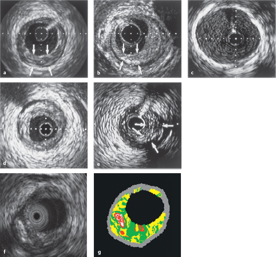
 Identification of atheromas that are angiographically not visible in the proximal vessel segment (especially in the area of the left coronary main stem)
 Degree of stenosis as percentage of the vessel diameter and cross-section before and after intervention
 Assessment of procedural success after coronary interventions (Fig. 29.5):
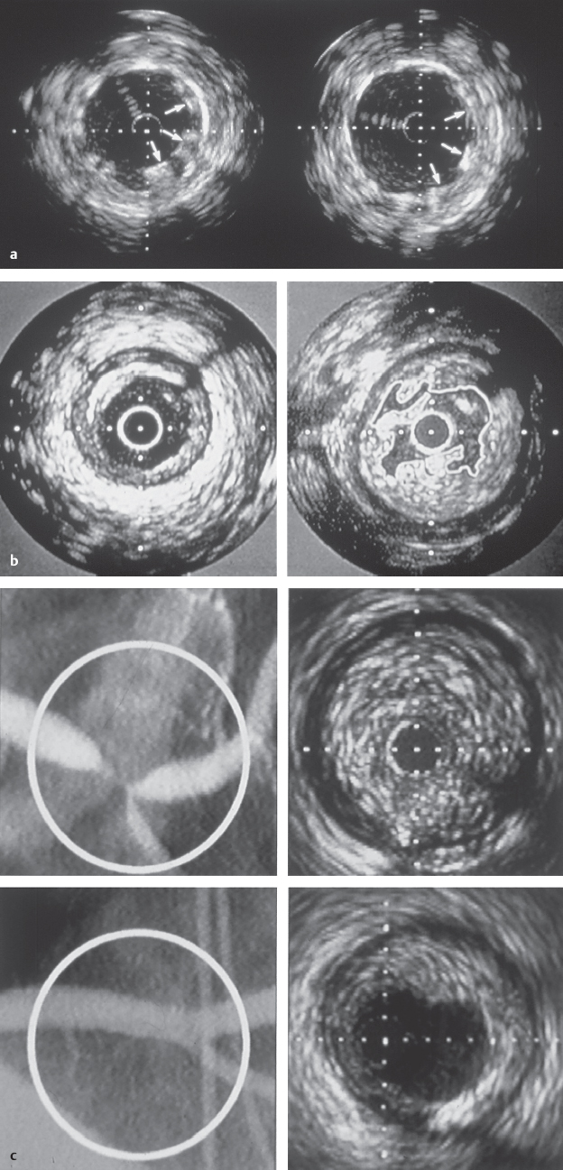
 Complications
 Status/Significance of the Method
Intracoronary Pressure and Doppler Measurements
 Basics
Intracoronary Pressure Measurement
 Instruments
 Procedure
 The guidewire is left in the storage coil and the coil is filled with 10 mL saline.
 The wire is connected to the control unit and calibrated with atmospheric pressure (for this the storage coil has to lie flat).
 If possible a guiding catheter (6F) without side holes should be used. Otherwise the guiding catheter may measure a combination of aortic and ostial occlusion pressure rather than the unadulterated aortic pressure, as required.
 The atraumatic tip of the wire can be preshaped according to the coronary anatomy.
 Then the guidewire is advanced so that the probe is at the distal end of the guiding catheter (at the transition from the radiopaque part of the pressure wire).
Stay updated, free articles. Join our Telegram channel

Full access? Get Clinical Tree


