31 Heart Valve Interventions
Percutaneous Mitral Commissurotomy
 Introduction
Percutaneous transluminal mitral commissurotomy (PTMC) was performed for the first time by Inoue in 1984. Due to its good acute and long-term results, it is considered an established nonsurgical treatment of mitral stenosis. Similarly to surgical commissurotomy, the balloon catheter causes the tearing or cracking of the fused commissures.
 Indications and Contraindications
Patients are selected on the basis of symptoms and echocardiographic findings. In general, percutaneous commissurotomy is indicated for
![]() Symptomatic patients (≥ NYHA II) with moderate to severe mitral stenosis (valve area ≤ 1.5 cm2)
Symptomatic patients (≥ NYHA II) with moderate to severe mitral stenosis (valve area ≤ 1.5 cm2)
![]() No or only mild mitral regurgitation (≤ grade II)
No or only mild mitral regurgitation (≤ grade II)
![]() Intact subvalvular apparatus
Intact subvalvular apparatus
![]() Only minimal subvalvular fibrosis and only mild or moderate calcification of the valve
Only minimal subvalvular fibrosis and only mild or moderate calcification of the valve
The probability of success and of complications of percutaneous commissurotomy can be assessed using a scoring system, which is based on echocardiographic criteria (Table 31.1). Patients with a score ≤ 8 usually have the best acute and long-term outcomes, whereas patients with a score ≥ 12 are likely to derive more benefit from surgical treatment.
Percutaneous valvuloplasty is contraindicated with
![]() Demonstration of thrombi in the left atrium
Demonstration of thrombi in the left atrium
![]() Severe mitral regurgitation (≥ grade III)
Severe mitral regurgitation (≥ grade III)
Criterion | Valve morphology | Score |
Leaflet mobility | Only isolated impairment of mobility at the tip of the leaflets Reduced mobility of the mid-portion and base of leaflets Valve leaflets move forward during diastole, predominantly at the base No or only minimal mobility of the leaflets during diastole | 1 2 3 4 |
Valvular thickening | Leaflets have near normal thickness (4–5 mm) Marked thickening of the margins (5–8 mm) Marked thickening of the entire leaflets (5–8 mm) Marked thickening of the entire valve (> 8–10 mm) | 1 2 3 4 |
Subvalvular thickening | Minimal thickening of chordal structures directly below the valve Thickening of up to one-third of the length of the chordae Thickening extending to the distal third of the chordae Marked thickening with shortening of the chordae extending to the papillary muscles | 1 2 3 4 |
Valvular calcification | Individual, localized calcifications Multiple areas of calcifications, limited to the leaflet margins Calcifications extend to the mid-portion of the leaflets Marked calcifications of almost the entire leaflet | 1 2 3 4 |
 Instruments (Fig. 31.1)
The instruments needed for commissurotomy with the Inoue balloon are available as a complete set, which consists of
![]() Inoue balloon catheter: dual-lumen coaxial PVC catheter, size 12F (length 70 cm)
Inoue balloon catheter: dual-lumen coaxial PVC catheter, size 12F (length 70 cm)
![]() Stretching tube (1.2 mm outer diameter, length 80 cm)
Stretching tube (1.2 mm outer diameter, length 80 cm)
![]() Dilator (14F, length 70 cm)
Dilator (14F, length 70 cm)
![]() Stainless-steel guidewire with spiral tip (0.025 in., length 170 cm)
Stainless-steel guidewire with spiral tip (0.025 in., length 170 cm)
![]() Stylet (0.038 in., length 80 cm)
Stylet (0.038 in., length 80 cm)
![]() Inflation syringe
Inflation syringe
![]() Caliper
Caliper
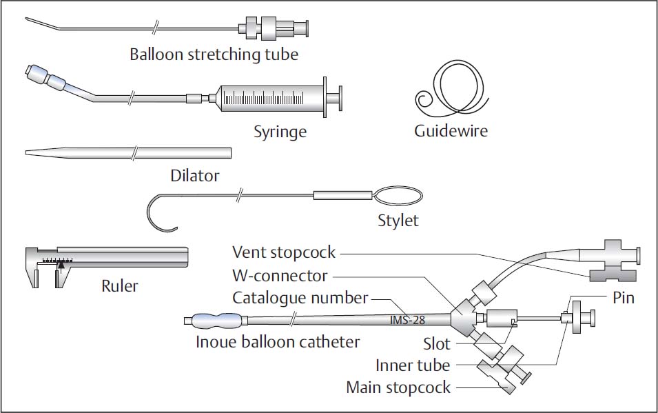
Fig. 31.1 Instruments for percutaneous mitral commissurotomy with the Inoue balloon.
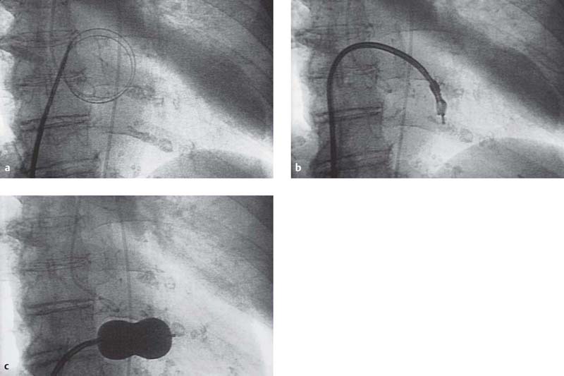
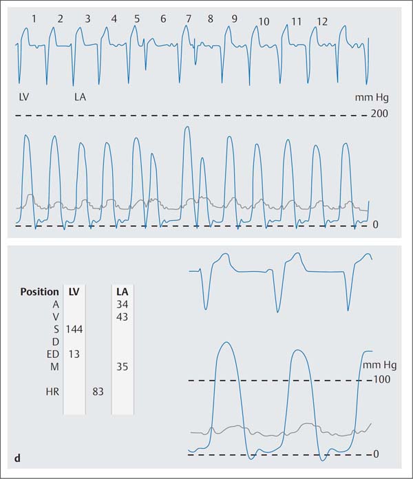
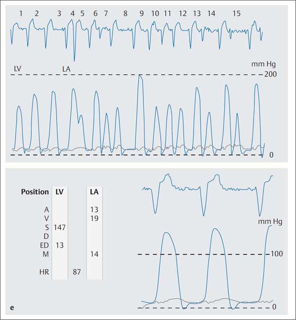
Fig. 31.2 a–e Percutaneous transluminal mitral commissurotomy in a 76-year-old woman with severe mitral stenosis.
a The stainless-steel guidewire is advanced into the left atrium; dilatation of the atrial septum with the dilator.
b Inoue catheter at the mitral valve.
c Mitral commissurotomy: the inflated Inoue-balloon is positioned in the mitral orifice (AP projection).
d Simultaneous pressure recording of the left ventricle (LV) and left atrium (LA) before mitral commissurotomy (mitral valve area 0.6 cm2).
A | a-wave |
V | v-wave |
S | systolic pressure |
D | diastolic pressure |
BD | beginning of diastole |
ED | end of diastole |
M | mean pressure |
HR | heart rate |
e Simultaneous pressure recording of the LV and LA after mitral commissurotomy (mitral valve area 1.9 cm2).
 Procedure: Inoue Technique
Pretests/Patient Preparation
![]() Transesophageal echocardiography for all patients to exclude atrial thrombi on the day of the procedure
Transesophageal echocardiography for all patients to exclude atrial thrombi on the day of the procedure
![]() Informed consent of the patient regarding procedure and risks
Informed consent of the patient regarding procedure and risks
![]() Endocarditis prophylaxis
Endocarditis prophylaxis
![]() Otherwise patient preparation as per usual for cardiac catheterization of mitral stenosis (including transseptal puncture)
Otherwise patient preparation as per usual for cardiac catheterization of mitral stenosis (including transseptal puncture)
Sequence of the Procedure (Fig. 31.2)
A basic requirement for percutaneous mitral commissurotomy is successful transseptal puncture (Chapter 9). Ideally, the commissurotomy is performed immediately following the diagnostic cardiac catheterization.
1. Puncture of the right femoral vein and placement of an 8F sheath
2. Placement of a 5F sheath into the left femoral artery with placement of a pigtail catheter in the left ventricle
3. Ventriculography to evaluate for mitral regurgitation
4. Placement of the pigtail catheter in the aortic root
5. Transseptal puncture with the Brockenbrough catheter (Chapter 9)
6. Administration of heparin (100 IU/kg body weight IV)
7. Hemodynamic evaluation with calculation of the pressure gradient across the mitral valve and mitral valve area after placement of the pigtail catheter in the left ventricle
8. Balloon selection based on patient height (Table 31.2)
9. Preparation of the balloon (Fig. 31.3): removal of air using the flush connection with diluted contrast medium (ratio 1:4). The diameter of the Inoue balloon is variable within the dimensions indicated above and is determined by the amount of contrast medium in the dilatation syringe. The dilatation syringe is filled with the contrast medium mixture up to the red markers and connected to the main stopcock. Subsequently balloon dilatation, assessment of the diameter (caliper), and deflation of the balloon.
10. The balloon extender is introduced into the lumen of the balloon catheter and connected to the Luer lock. Then, the internal catheter including the balloon extender is advanced to the W-connector and locked there. This elongates and stiffens the end of the catheter.
11. Through the Brockenbrough catheter the stainlesssteel guidewire is positioned in the left atrium. The tip of the Brockenbrough catheter should not rest against the left atrial wall.
12. When the guidewire is correctly positioned, the Brockenbrough catheter and venous sheath are withdrawn.
13. Via the guidewire the femoral puncture site and the puncture site of the atrial septum are dilated with the 14F dilator (Fig. 31.4a).
14. The Inoue catheter is introduced and advanced until the balloon is mostly in the left atrium. The stretching tube is pulled back by ~2 to 3 cm within the internal catheter, which makes the balloon tip more mobile (Fig. 31.4b, c).
15. The balloon catheter is further advanced with the internal catheter, until the balloon segment is entirely in the left atrium (Fig. 31.4 d).
16. The internal catheter is released from the W-connector and pulled back until resistance is felt, which returns the balloon to its original shape (Fig. 31.4e, f).
17. After further advancement of the balloon catheter, the guidewire and stretching tube are removed together.
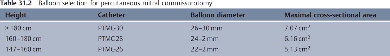
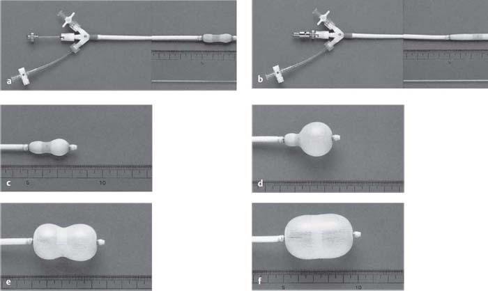
Fig. 31.3 a–f The Inoue balloon catheter.
a Original balloon catheter.
b After introduction of the stretching tube.
c After injection of 1 to 5 mL diluted contrast medium.
d–f The balloon catheter with three stages of increasing inflation.
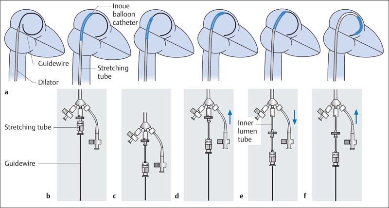
Fig. 31.4 Introduction of the Inoue balloon into the left atrium (see text for details).
 Caveat: Never remove the guidewire with the balloon stretched: this could cause kinking of the balloon and perforation by the stretching tube.
18. Crossing of the mitral valve (30° RAO projection):
– Standard method:
– The distal balloon end is filled with 1 to 2 mL of diluted contrast medium (Fig. 31.5a).
– The stylet is inserted to the distal end of the balloon catheter. This gives the catheter a “J”-configuration with the tip pointing downward (Fig. 31.5b). The stylet tip can be preshaped corresponding to the respective atrial size (Fig. 31.5c).
– By rotating the stylet counterclockwise, the balloon catheter is directed anteriorly to the valve orifice. If the stylet is now pulled back by 4 to 5 cm, the balloon moves through the valve into the ventricle. Usually this procedure has to be done repeatedly as the balloon rarely crosses the valve on the first attempt.
– Alternative method:
– The catheter lies in a large loop in the left atrium (Fig. 31.6a).
– The stylet is pulled back by 5 to 6 cm, which makes the balloon segment flexible. By rotating the stylet clockwise the balloon tip is led to the posterior and caudal wall of the left atrium (Fig. 31.6b).
– With the stylet fixed in place, the balloon catheter is guided at the caudal atrial wall across the mitral valve into the left ventricle (Fig. 31.6c).
19. Dilatation of the mitral valve (Fig. 31.7):
– If the balloon is located in the left ventricle, the distal half of the balloon is filled with contrast medium and the catheter is moved back and forth a few times to establish that it can be moved freely in the left ventricular cavity.
– Subsequently the balloon is carefully pulled back into the mitral orifice.
– A quick and complete manual inflation of the entire balloon is then performed.
 It is important that the balloon is securely anchored in the mitral orifice during the dilatation.
– As soon as the balloon is completely expanded, it is immediately emptied again (maximum dilatation time 5 seconds).
20. Assessment of procedural success:
– Make repeated hemodynamic measurements with repeated calculation of the pressure gradient and the mitral valve area.
– Repeat left ventriculography to exclude or demonstrate mitral regurgitation post procedure.
– If the initial dilatation was not sufficient, the balloon diameter is increased stepwise by 1 to 2 mm, and the dilatation procedure is repeated (always under the condition that there is no significant mitral regurgitation).
21. Catheter removal:
– For this the catheter has to be straightened again. First, the catheter is withdrawn until a slight resistance is felt at the atrial septum.
– Then the guidewire is introduced up to the left atrium. The guidewire is positioned in the left atrium in such a way that it protrudes at least 10 cm from the catheter tip.
– The stretching tube is advanced via the guidewire to the internal catheter and locked.
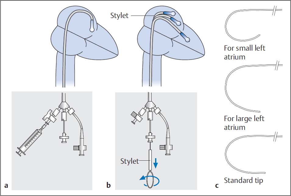
Fig. 31.5 Crossing of a mitral stenosis with the Inoue-balloon. Standard method (a) and (b). Adapting the stylet tip to various atrial diameters (c) (see text for details).
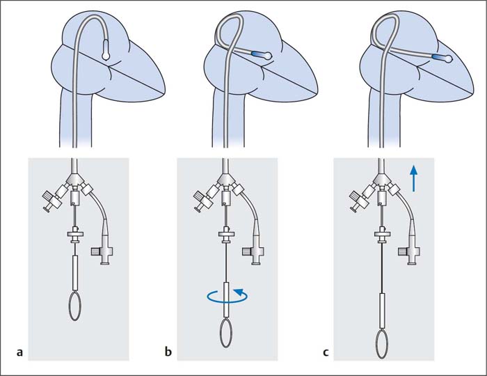
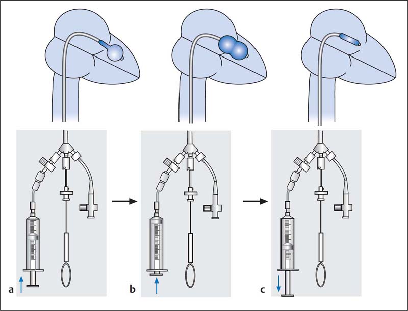
Fig. 31.7 Valvuloplasty of a mitral valve stenosis (see text for details).
– Then the balloon is straightened and locked at the connector, and the entire system is removed.
22. A diagnostic saturation run to quantify a left-to-right shunt at the atrial level can optionally be done.
Possible Problems
![]() Kinking and twisting of the balloon. Solution: Unlocking and pull-back of the inner catheter at the W-connector, short expansion and emptying of the balloon, then introduction of the wire, introduction of the inner catheter and locking with the stretching tube; then stretching of the system and removal.
Kinking and twisting of the balloon. Solution: Unlocking and pull-back of the inner catheter at the W-connector, short expansion and emptying of the balloon, then introduction of the wire, introduction of the inner catheter and locking with the stretching tube; then stretching of the system and removal.
![]() Twisting of the internal lumen: To avoid this problem, the balloon should always be rotated only at the W-connector and the internal wire should be as distal as possible.
Twisting of the internal lumen: To avoid this problem, the balloon should always be rotated only at the W-connector and the internal wire should be as distal as possible.
 Procedure: Double-balloon Technique
![]() An alternative to the Inoue technique is the double-balloon technique, which is usually performed with antegrade crossing of the mitral valve after transseptal puncture with the Mullins sheath.
An alternative to the Inoue technique is the double-balloon technique, which is usually performed with antegrade crossing of the mitral valve after transseptal puncture with the Mullins sheath.
![]() A sufficiently large catheter is advanced across the mitral valve via the left ventricle into the descending thoracic aorta, so that two guidewires can be positioned there.
A sufficiently large catheter is advanced across the mitral valve via the left ventricle into the descending thoracic aorta, so that two guidewires can be positioned there.
![]() Two guidewires (length 260 cm, 0.035 in., J-tip) are advanced via the catheter.
Two guidewires (length 260 cm, 0.035 in., J-tip) are advanced via the catheter.
![]() After removal of the catheter, the puncture site in the atrial septum is dilated with a 5-mm balloon catheter (advanced via one of the guidewires).
After removal of the catheter, the puncture site in the atrial septum is dilated with a 5-mm balloon catheter (advanced via one of the guidewires).
![]() Then two valvuloplasty balloons (diameter 18 mm, for description see page 368, Aortic Valvuloplasty) are advanced via the guidewire and positioned in the mitral orifice. Then both balloons are quickly and simultaneously expanded manually with 50-mL syringes (diluted contrast medium as above), until the indentations have disappeared from both balloons.
Then two valvuloplasty balloons (diameter 18 mm, for description see page 368, Aortic Valvuloplasty) are advanced via the guidewire and positioned in the mitral orifice. Then both balloons are quickly and simultaneously expanded manually with 50-mL syringes (diluted contrast medium as above), until the indentations have disappeared from both balloons.
![]() Subsequent measurements and left ventriculography are performed as with the Inoue technique.
Subsequent measurements and left ventriculography are performed as with the Inoue technique.
 Complications
Severe complications following PTMC are rare and are not anymore frequent than after surgical commissurotomy. The risk of severe complications is especially increased for
![]() Older patients
Older patients
![]() Patients with NYHA IV heart failure
Patients with NYHA IV heart failure
![]() Patients with an echo score > 12
Patients with an echo score > 12
To avoid thromboembolic complications some operators recommend effective anticoagulation starting at least 6 weeks before the procedure. However, oral anticoagulation does not exclude the possibility of thrombus formation in the atrium. Thus, in general all patients should undergo transesophageal echocardiography ideally immediately before the procedure.
Severe grade IV mitral regurgitation is observed in 2 to 5 % of cases. Worsening of preexisting mitral regurgitation is seen in up to 30 % of cases.
Due to the transseptal access, an atrial septal defect develops in up to 16 % of patients. The resulting left-to-right shunt is usually mild and clinically without consequences. It has been shown that the left-to-right shunt markedly regresses over the course of the ensuing months and that in ~60 % of patients the shunt cannot be detected after 10 months.
In summary, depending on the patient population and the different techniques (double-balloon or Inoue technique) the complication rates are as follows:
![]() Mortality: 0.1 to 1.4 %
Mortality: 0.1 to 1.4 %
![]() Mitral regurgitation grade IV: 1 to 5.2 %
Mitral regurgitation grade IV: 1 to 5.2 %
![]() Thromboembolism: 0.6 to 3.1 %
Thromboembolism: 0.6 to 3.1 %
![]() Atrial septal defect: 3 to 16 %
Atrial septal defect: 3 to 16 %
![]() Pericardial tamponade: 0.2 to 4.1 %
Pericardial tamponade: 0.2 to 4.1 %
![]() Emergency surgery: 1.2 to 2.4 %
Emergency surgery: 1.2 to 2.4 %
 Acute and Long-term Results
On average the mitral valve area can be increased by ~1 cm2, while the mean transvalvular pressure gradient decreases by ~9 mm Hg. The technical success rate is >98%.
The causes of technical failure are usually technical difficulties, complications of transseptal puncture, or a failure to cross the mitral orifice within the setting of a very severe stenosis.
The restenosis rate in the intermediate term (32 months) is ~5 %. Similar outcomes are expected in the long term (clinical events, surgical valve replacement) as after surgical mitral commissurotomy, especially with an echo score of ≤ 8.
 Evaluation of the Techniques
The Inoue technique has the advantage of easier handling, and, with the use of a single balloon catheter, provides the option of adjusting the size of the balloon diameter. In contrast, the more complex double-balloon technique can achieve a relatively larger mitral valve area; however, there is a slightly higher rate of procedural complications.
Personal view
We prefer the Inoue technique because of its well-documented safety and clinical outcomes. Clinical results do not differ between the techniques.
In select patients, we perform the intervention with intraprocedural transesophageal echocardiography (TEE) (e.g., after prosthetic aortic valve replacement or with severe renal insufficiency, when either the aortic valve cannot be crossed retrogradely or when contrast medium administration to evaluate for mitral regurgitation should be avoided).
The technique can also safely be used in patients with significant pulmonary hypertension and has good clinical results.
In patients with significant concomitant tricuspid regurgitation, the surgical approach is preferred with simultaneous tricuspid valve reconstruction.
Mitral Valve Interventions for Mitral Regurgitation
 Basics
Mitral regurgitation is a substantial cause of morbidity and mortality, especially in older patients. The primary causes are either functional regurgitation due to increasing dilatation of the left ventricle with insufficient coaptation of the leaflets or degenerative changes of the leaflets of variable etiology. Currently, the best available therapy is surgical reconstruction of the valve, also possible using a minimally invasive technique, or valve replacement. However, numerous patients are at high risk for perioperative mortality due to comorbidities, reduced left ventricular function and diameter, previous surgery, or age. Interventional techniques for percutaneous mitral valve reconstruction are being developed.
The most important therapeutic strategies are indirect annuloplasty via devices that are implanted in the coronary sinus to reduce the size of the mitral valve annulus (MONARC, CARILLON) or to coapt the mitral valve leaflets analogously to the surgical technique by Alfieri (MitraClip [Abbott Vascular, Santa Clara, CA, USA]). Additional procedures are in preclinical development.
Crucial for the interventional therapy of mitral regurgitation is the echocardiographic evaluation of the anatomy, the functional anatomy, and the exact mechanism of the mitral regurgitation. Close cooperation among echocardiographer, interventionalist, cardiac surgeon, and anesthesiologist are important for successful treatment. This cooperation is needed not only for the decision regarding surgical versus interventional management, but also for the procedure itself as well as the postprocedural care.
The following discussion is limited to the MitraClip technique (Fig. 31.8), which essentially forms a mitral valve with a double orifice (Fig. 31.9).
 Indications and Contraindications
The indication for an interventional approach for mitral regurgitation depends on the one hand on clinical factors, and on the other hand on the anatomical and functional characteristics of the mitral valve.
The primary prerequisite for an intervention on the mitral valve is clinical heart failure, which is primarily due to severe mitral regurgitation (grade III or IV).
Clinical indications for an interventional approach are especially the following:
![]() Significant comorbidities which substantially increase surgical risk. Important factors include advanced lung disease, advanced kidney disease, or significant frailty.
Significant comorbidities which substantially increase surgical risk. Important factors include advanced lung disease, advanced kidney disease, or significant frailty.
![]() Previous cardiac surgery
Previous cardiac surgery
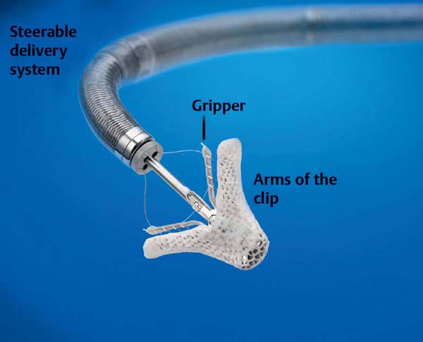
Fig. 31.8 MitraClip with delivery catheter.
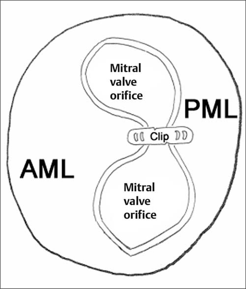
Fig. 31.9 Mitral valve with two orifices after clip implantation.
![]() Surgery having been declined by the patient even after a detailed discussion with an experienced surgeon
Surgery having been declined by the patient even after a detailed discussion with an experienced surgeon
![]() Determination of the surgical mortality risk: STS score > 12 %, log Euroscore II > 20 %
Determination of the surgical mortality risk: STS score > 12 %, log Euroscore II > 20 %
Echocardiographic Criteria
Prerequisite is the echocardiographic confirmation of a mitral regurgitation grade III or IV, preferably by several modalities (see Table 31.3):
Specific indications (echocardiographic parameters):
![]() Degenerative mitral regurgitation (Carpentier type II mitral regurgitation)
Degenerative mitral regurgitation (Carpentier type II mitral regurgitation)
– Proplapse or flail of the A2 and/or P2 segment
– Gap between the flail segments < 10 mm
– Flail or prolapse width < 15 mm
![]() Functional mitral regurgitation (Carpentier type 1 or type IIIb mitral regurgitation)
Functional mitral regurgitation (Carpentier type 1 or type IIIb mitral regurgitation)
– Dominant mitral regurgitation jet in the area of the A2/P2 segments
– Underlying disease: dilated cardiomyopathy and/or remodeling in ischemic heart disease
– Coaptation length of the leaflets ≥ 2mm
– Coaptation depth ≤ 11 mm
Contraindications (echocardiographic parameters):
![]() General
General
– Rheumatic valve disease
– Mitral valve orifice < 4 cm2
– Leaflet length < 11 mm
– Vegetations and suspected endocarditis
– Substantial thickening of the mitral leaflets, e.g., rheumatic heart disease
– Severe calcifications of the mitral valve leaflets, which make successful grasping of the leaflets unlikely
![]() In functional mitral regurgitation
In functional mitral regurgitation
– Length of the coaptation area of the leaflets < 2 mm
– Coaptation depth > 11 mm
![]() In degenerative mitral regurgitation
In degenerative mitral regurgitation
– Flail height, gap between both leaflets ≥ 10 mm
– Flail width ≥ 15 mm
Table 31.3 Echocardiographic criteria used to assess the degree of mitral regurgitation
Parameter | Measurement |
Color Doppler jet | > 30% of the LA area or > 6 cm2, extent in the left atrium, eccentricity |
Backflow | Up to the pulmonary veins |
Vena contracta | ≥0.5 cm in the parasternal long axis |
Regurgitation volume | ≥45 mL/beat |
Regurgitation fraction | ≥40% |
Effective regurgitation orifice (ERO) | ≥0.3 cm2 |
 Preprocedural Studies
The mitral valve is a complex anatomical structure consisting of the mitral valve annulus, two leaflets (anterior and posterior) and the chordae tendineae, which connect the two leaflets with the papillary muscles. Function and geometry of the mitral valve are significantly affected by the anatomical and functional conditions of the left atrium and left ventricle. Both mitral leaflets are divided into three segments from laterally to medially, P1–P3 (posterior leaflet) and A1–A3 (anterior leaflet), which is important for the understanding of mitral regurgitation and for the planning of the procedure (Fig. 31.10).
Consequently, a detailed echocardiographic examination prior to and during the procedure is crucial for the success of the intervention.
The initial screening is done with transthoracic echocardiography (TTE). However, TEE is also obligatory in the screening of these patients to characterize precisely the valve morphology. Three-dimensional TEE is highly recommended for screening to identify patients in whom grasping of the leaflets is unlikely to be successful; it is also of great significance during the procedure (orthogonal orientation of the clip to the valve commissure).
The echocardiographic examination is focused on
![]() Etiology of the mitral regurgitation: degenerative, functional, mixed
Etiology of the mitral regurgitation: degenerative, functional, mixed
![]() Leaflets: flail, prolapse, restrictive, cleft, calcifications, vegetations, etc.
Leaflets: flail, prolapse, restrictive, cleft, calcifications, vegetations, etc.
– Flail-width, coaptation area, coaptation depth, etc.
– Leaflet thickness (myxomatous degeneration?)
– Leaflet length
![]() LV function and diameter: left ventricular ejection fraction (LVEF), LVEDD
LV function and diameter: left ventricular ejection fraction (LVEF), LVEDD
![]() LA size
LA size
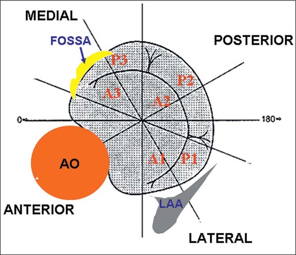
Fig. 31.10 Segments of the mitral valve and anatomical orientation.
![]() Measurement of the distance between fossa ovalis and coaptation (four-chamber view)
Measurement of the distance between fossa ovalis and coaptation (four-chamber view)
Stay updated, free articles. Join our Telegram channel

Full access? Get Clinical Tree


