Fig. 8.1
Patient positioned on left edge of OR table
Standard hemodynamic monitoring is used with a radial arterial line for systemic blood pressure monitoring. A central venous line or a pulmonary artery catheter can be used for central access of the cardiac monitoring. CO2 insufflation at a pressure of 8–10 mmHg is used in the left pleural space to help with exposure. Special consideration has to be given to hemodynamic effects related to the insufflation as the increased pressure of CO2 may cause tamponade physiology and affect hemodynamics. Single lung ventilation can also cause hypoxemia and hypercarbia which hence may make the patient unstable.
External defibrillator patches are placed on the chest (Fig. 8.2) and the patient is positioned supine with the left chest elevated to 30° with the aid of a small bolster under the left chest. The operative side arm with protective padding is hung loosely and supported by a sheet. In the female patient, the breast is positioned medially after sterile skin preparation, and is secured by an adhesive sheet during the draping.
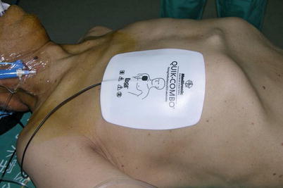
Fig. 8.2
The external defibrillator pads on chest
8.1.2 Surgical Technique
The port sites are marked on the patients skin (Fig. 8.3) before the incision is made. The camera port mark is on a transverse line midway between the suprasternal notch and the xiphoid process. The elevation of the camera port is located about 3 cm lateral of the midclavicular line (MCL), any place from 4 to 6 cm medial of the anterior axillary line (AAL) depending on the body habitus. This location is typically at the 4th or 5th ICS but depends on the body habitus and the length of the sternum. The location of the left instrument port is about the breadth of four fingers from the camera mark at about the same elevation, and always in the seventh ICS. The right instrument port is about the breadth of four fingers from the camera port at about the same elevation, and always in the third ICS. The three ports are in the almost same line. However, our experience is that left port should be little lower in order to prevent collisions. After deflation of the left lung, a camera port is inserted through the middle incision and carbon dioxide insufflation is initialed and maintained at an average of 6–8 mmHg, which may be increased to 12 mmHg as long as patients are able to maintain satisfactory hemodynamic status. A 30 degree-angle upward camera is inserted, and the thoracic cavity, the location and course of the LITA are examined. The left and the right instrument ports are inserted (Fig. 8.4). The surgical cart with 4 arms is brought in and docked to the camera and the instrument arm ports (Fig. 8.5).
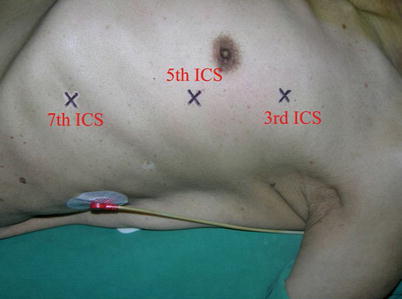
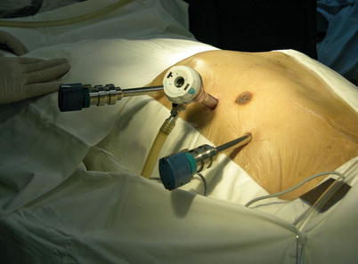
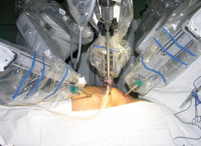
Fig. 8.3
Ports placement for LITA harvesting
Fig. 8.4
Ports placement for LITA harvesting
Fig. 8.5
The da Vinci S Surgical System set up
After access to the left pleura space, a 30° upward endoscope is inserted to the camera port by the patient-side surgeon. The entire mediastinum is inspected. CO2 is insufflated for adequate visualization and working space for hemodynamic tolerance. The required dose of CO2 is nominally 8 mmHg (usually 8–10, 12–15 mmHg maximum for fatty mediastinum). LITA location and adhesions are carefully examined before surgery. The LITA is identified and pulsation can be observed. Both pedicle and skeletonized harvesting techniques can be applied. The skeletonized harvesting technique is similar to that used in open surgery or endoscopy.
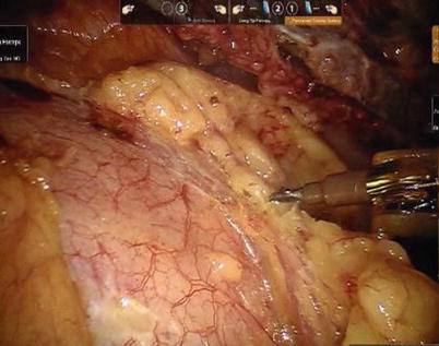
First, the pleura parietalis, fascia and muscles covering the LITA are transected along the entire length (Fig. 8.6). This allows exposure of the vessel regardless of the amount of fat or muscle covering the mammary artery. The skeletonized LITA is dissected from the lateral edge medially using blunt dissection and short bursts of low power monopolar cautery to mobilize the anterior attachments (Fig. 8.7). Small intercostal branches are ligated with monopolar energy in a painting stroke then transected (Fig. 8.8). Large intercostal branches are clipped for hemostasis (Fig. 8.9). The entire length of LITA is dissected from the first intercostal branch to the diaphragm. Starting at about the 3rd ICS, short segments of periarterial connective tissue are left attached to help stabilize the ITA when the surgeon prepares the end for anastomosis.
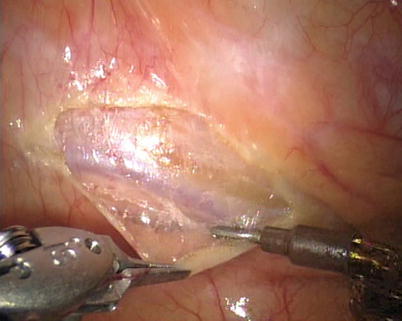
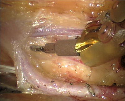
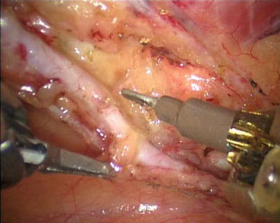
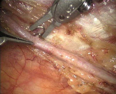
Fig. 8.6
Dissecting the pleura parietalis, fascia and muscles covering the LITA
Fig. 8.7
The skeletonized LITA harvesting is performed using low power cautery
Fig. 8.8
The small branch is ligated with monopolar energy
Fig. 8.9
Large intercostal branches are clipped for hemostasis
The right ITA (RITA) can be harvested through the same approach for the LITA harvesting. After the instruments are inserted into the robotic ports, the anterior mediastinum is dissected and the instruments gain accesses to the right pleural space (Fig. 8.10). The RITA is identified. The pedicle or skeletonized harvesting technique is similar to that used in robotic LITA harvesting (Figs. 8.11, 8.12, 8.13, and 8.14). For RIMA to be the right coronary bypass graft, the RITA can also be robotically harvested using right chest approach, just the opposite to the left chest approach (Figs. 8.15 and 8.16).
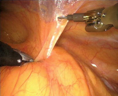
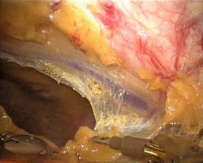
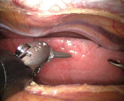
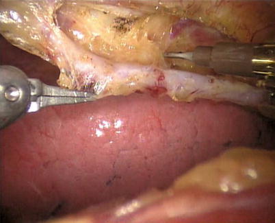
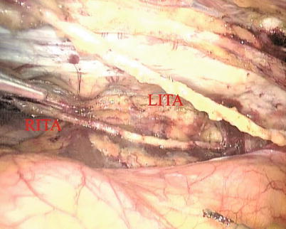
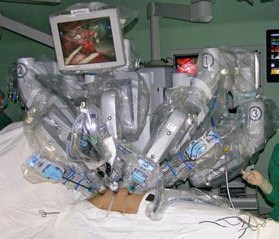
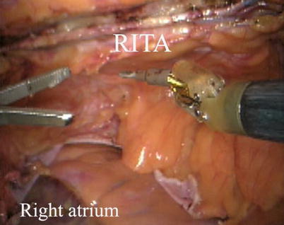
Fig. 8.10
The anterior mediastinum is dissected
Fig. 8.11
Opening the right pleural cavity for exposing the RITA
Fig. 8.12
RITA is identified
Fig. 8.13
RITA is harvested in skeletonized fashion
Fig. 8.14
The double ITAs are harvested
Fig. 8.15
The surgical system set-up of right approach for RITA harvesting
Fig. 8.16
RITA is robotically harvested in a right approach
8.1.3 The Surgical Experience and Learning Curves
There is an initial learning curve with the technique of robotic-assisted endoscopic ITAs harvest. From April 2007 to May 2013, 220 patients accepted totally robotic coronary bypass on beating heart (BH-TECAB, 100 cases) or robotic minimally invasive coronary bypass on beating heart (MIDCAB, 120 cases). The mean age was 58.9 ± 10.1 (33–78) years. ITA was harvested robotically in all cases successfully without damage leading to abandon, including LITAs, RITAs and double-ITAs harvesting with da Vinci S or Si system. The mean harvesting time was 30.8 ± 8.7 (16–52) min. A significant learning curve (Fig. 8.17) for harvesting time was noted: y(min) = 57.8 − 5.5 ln(x); (r 2 = 0.342; P < 0.01)
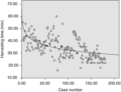
Fig. 8.17
The learning curve of ITAs harvest (y(min) = 57.8 − 5.5 ln(x); r 2 = 0.342, p = 0.000)
The development of robotic surgical devices is a prerequisite for performing TECAB. However, TECAB is a highly complex procedure consisting of several but not routinely performed surgical steps, which requires a modular and step approach [5]. An important step of this procedure is the robotic ITA harvesting.
For the patients undergoing robotic harvesting, the preoperative three-dimensional computer tomography images are needed to be taken to evaluate the quality of the target ITA. The robotic-enhanced IMA takedown is a prerequisite for TECAB or MIDCAB operations and can be safely implemented. With a noted learning curve, the surgeon will harvest the target ITA in an acceptably shorter time. In this study the harvesting time stayed stable after about 30 cases and decreased as case number increased. The harvesting time was reduced to an acceptable duration between 25 and 30 min. Long preparation time at the beginning may be explained by the complexity of this new system and the lack of clinical experience of the operation team [6].
Bolotin and associates [7] reported robotic LITA harvesting speed in a range of 39–48 min when using the dog model. Learning curves and long preparation time at the beginning of implementation had also been described by Falk and associates [8] and Reuthebuch and coworkers [9]. The Falk group presented a LITA takedown time of about 40 min after 50 cases. The Reuthebuch study noted that after the learning curve, a target LITA harvesting speed in the 35 min range could be achieved.
In conclusion, robotic-enhanced IMA takedown can be safely implemented, and is prerequisite for TECAB operations. After overcoming learning curve, IMA takedown can be performed in an acceptable time. Demographics and chest size do not seem to influence ITA harvesting time. The rate of LITA injuries is comparable with the rate reported for conventional thoracoscopic harvesting [6].
8.2 Minimally Invasive Direct Coronary Artery Bypass Grafting (MIDCAB)
After LITA is completely mobilized, the pericardium is incised robotically, anterior to the left phrenic nerve and the small pericardial branches are carefully cauterized (Fig. 8.18). This helps in clearing the operative field and also proper placing of ITA. Then the left anterior descending artery (LAD) or the target vessels are identified (Fig. 8.19) and the corresponding anterior intercostal space is identified to confirm the proper placement of the small left anterior thoracotomy incision, usually 4 cm long in the 4th ICS. After systemic heparinization, with an activated clotting time (ACT) goal of 350 s, the LITA is dissected distally. The distal end of the artery is parked on the pericardium using a hemoclip (Fig. 8.20). If RITA is to be used for anastomosis, it is harvested prior to LITA harvest. RITA is harvested in its full length as a skeletonized conduit as described above in Fig. 8.16. If a free RITA is to be used for composite grafting, it is dissected at its origin, and the free RITA is parked on the pericardium. The small left anterior thoracotomy incision (about 4 cm) may be made in the fourth or fifth intercostal space (Fig. 8.21). And the left pleural cavity is entered and a retractor is placed in the incision (Fig. 8.22). The distal end of the artery is then prepared for anastomosis. LAD is stabilized with a cardiac stabilizer and LITA is anastomosed to LAD manually in the end to side fashion, using a continuous 7-0 Prolene suture (Fig. 8.23). The in situ LITA is always used as grafting to the LAD (Fig. 8.24), or sequentially to diagonal branch (Fig. 8.25). The LAD along with composite RITA can be used to the lateral wall grafts. In some instances, in situ RITA can be anastomosed to the LAD, and in situ LITA to the lateral wall vessels. All composite grafts are anastomosed prior to the coronary grafting.
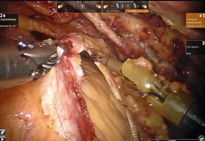
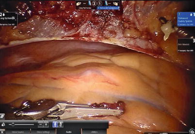
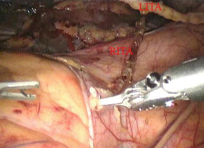
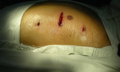
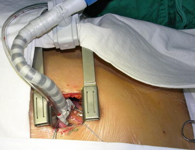
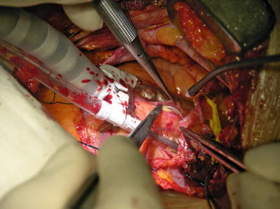
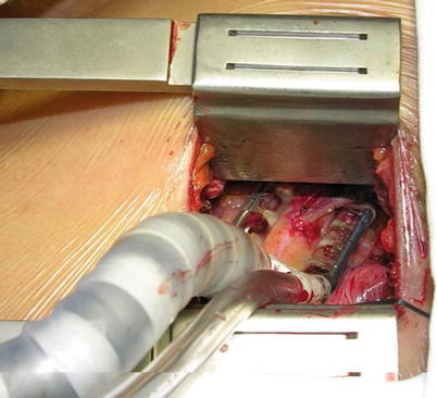
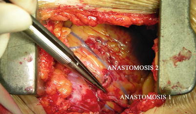
Fig. 8.18
The pericardium is opened
Fig. 8.19
Identifying the target vessel
Fig. 8.20
ITA is parked on the pericardium using a hemoclip
Fig. 8.21
A small left anterior thoracotomy incision may be made in the fourth or fifth intercostal space
Fig. 8.22
The retractor and cardiac stabilizer are used to expose the target vessel
Fig. 8.23
LITA is anastomosed to the LAD in the end to side fashion, using a continuous 7-0 Prolene suture
Fig. 8.24
LITA is anastomosed to the LAD
Fig. 8.25
LITA is sequentially anastomosed to LAD and diagonal branch
8.2.1 Surgical Experience and Learning Curves
One hundred and twenty (86 male and 34 female) patients of the study group underwent MIDCAB. The mean age was 58.9 years (38–77 years), the mean weight was 70.6 kg (44–100 kg). The mean height was 165.9 cm (153–178 cm). The mean left ventricular ejection fraction was 63.7 % (44–72 %) and the mean diameter of left ventricle was 44.8 mm (35–57 mm).
The mean operating-room time was 240.8 min (180–300 min) and the mean operating time was 182.9 min (160–200 min). The mean ITA harvesting time was 33.4 min (16–45 min) (Fig. 8.26).
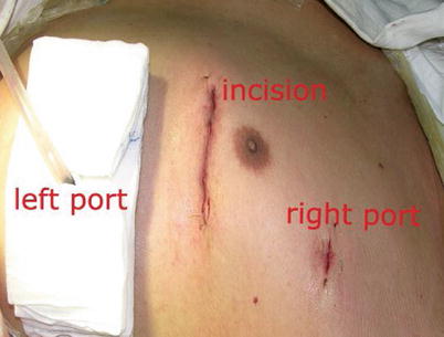
Fig. 8.26
The MIDCAB incision after operation
Double ITA harvesting (for “Y” type or sequence graft) was performed in three patients (Fig. 8.27). Right ITA harvesting was performed on five patients (Poor LITA quality was found in one patient. RITA to right coronary graft was performed on two patients and RITA to LAD graft on two patients.). RITA to RCA graft was performed on two patients (Fig. 8.28), LITA to diagonal branch graft on two patients, (Fig. 8.29), RITA to LAD graft on one patient (Fig. 8.30), sequential graft on four patients (Fig. 8.31), RITA to LAD and LITA to diagonal branch graft on two patients, (Fig. 8.32). LITA to LAD graft was performed on the rest of the patients (Fig. 8.33).
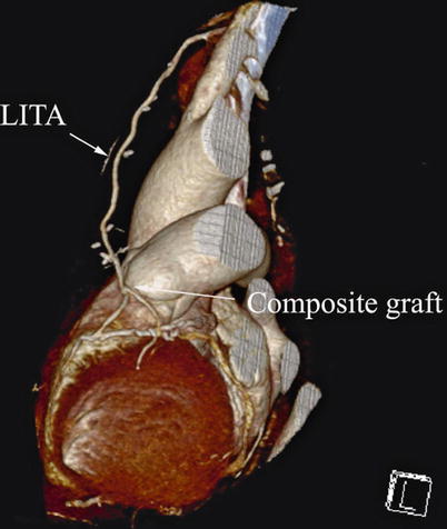
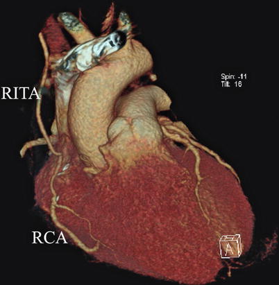
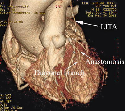
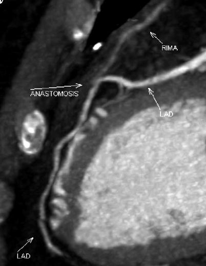
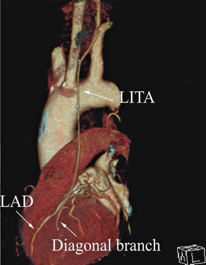
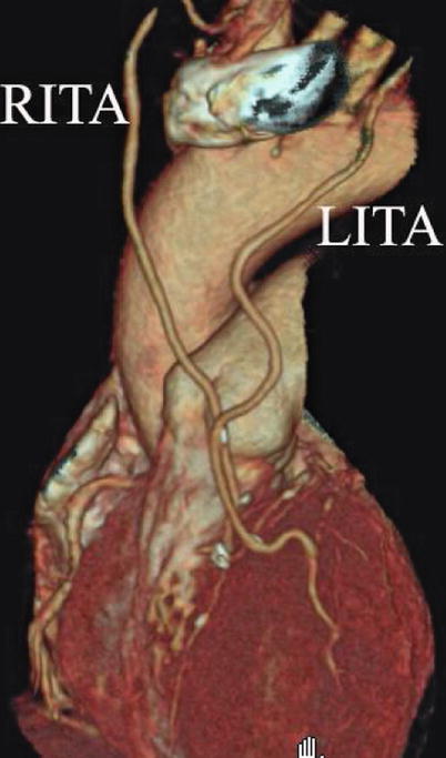

Fig. 8.27
“Y” type graft for LAD and diagonal branch using composite graft
Fig. 8.28
RITA is anastomosed to the RCA
Fig. 8.29
LITA to diagonal branch graft
Fig. 8.30
RITA is anastomosed to the LAD
Fig. 8.31
LITA is used in sequential graft
Fig. 8.32
LITA is anastomosed to diagonal branch and the RITA to LAD
Fig. 8.33
LITA is anastomosed to LAD
The mean graft flow was 21.3 ± 12.6 (15–56) ml/min. The graft patency was followed up by 64-MSCTA, and the patency rate was 97.1 %. The mean follow-up time was 13.1 (1–70) months. All patients had excellent cosmetic results (Figs. 8.34 and 8.35).
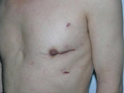
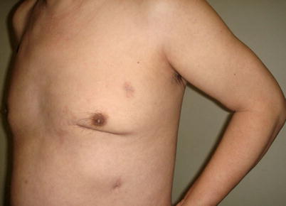
Fig. 8.34
A MIDCAB patient, 1 month after the surgery
Fig. 8.35
Three months after the surgery with well-healed incisions
8.3 Totally Endoscopic Coronary Artery Bypass Grafting (TECAB)
Conventional coronary artery bypass grafting provides complete revascularization with excellent long-term results for various clear-cut indications with a major favorable impact on the patient outcome and recurrence of adverse cardiac events. The success of catheter-based techniques for treating ischemic coronary syndromes, combined with the shift toward less invasive approaches, has renewed interest in minimally invasive approach. The current tendency is to perform operations through smaller and smaller incisions to reduce hospital stay and to hasten postoperative recovery. After the introduction of robotic telemanipulators, TECAB became feasible in the late 1990s. Didier Loulmet [1] performed the first TECAB procedure on arrested heart in 1999, and subsequently several investigators reported TECAB on beating heart [10, 11]. However, only a limited number of cases have been performed worldwide.
8.3.1 Surgical Technique
TECAB surgery on beating heart begins with satisfactory single lung ventilation of the patient, and patient positioning on the operating room table allows adequate access to the anatomy. After routine induction of anesthesia, double-lumen intubation is carried out for single right lung ventilation. External defibrillator patches are placed on the chest, and the patient is positioned supine with the left chest elevated 30° with the aid of a small bolster under the left chest (Fig. 8.36). The operative side arm with protective padding hung loosely is supported by a sheet. In female patients, the breast is positioned medially, and after sterile skin preparation, is secured by an adhesive sheet during the draping.
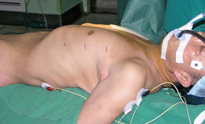
Fig. 8.36
The patient in a supine position with the left chest elevated 30°
Three 0.8–1.0-cm incisions are made in the 3rd, 5th, and 7th intercostal spaces (ICS) 2–3 cm medial to the anterior axillary line (Fig. 8.37). After deflation of the left lung, a camera port is inserted through the middle incision and carbon dioxide insufflation is initiated and maintained at an average of 6–8 mmHg, which may increase to 12 mmHg as long as patients are able to maintain satisfactory hemodynamic status. A 30° angle upward camera is inserted, and the thoracic cavity and the location and course of the LITA are examined. The left and the right instrument ports are inserted. The surgical cart with 4 arms is brought in and docked to the camera and the instrument arm ports (Figs. 8.38 and 8.39).
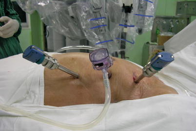
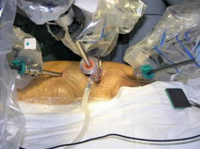
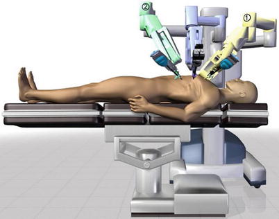
Fig. 8.37
The ports placement for LITA harvesting before TEACB
Fig. 8.38
The system set-up
Fig. 8.39
The patient side cart center column is aligned with the patient’s neck
The robotic system is used to harvest the LITA completely from the subclavian vein to the LITA bifurcation in a totally skeletonized fashion (Fig. 8.40). Hemoclips are used for larger branches, while cautery is used to cauterize and transect the smaller branches. The 1st and 2nd intercostal arterial branches are usually larger, therefore, Hemoclips are used (Fig. 8.41). In a few cases, LITA is harvested with the accompanying veins in case of close proximity of arteries and veins. The LITA is left attached to the chest wall with the connecting areolar tissue to prevent it from hanging over the pericardium. The pericardial fat is removed (Fig. 8.42) and pericardiotomy is performed (Fig. 8.43). The pericardium over the apex of the left ventricle is left intact to prevent herniation of the heart, and the target vessel is identified using a 30 degree-angle-downward camera (Fig. 8.44).
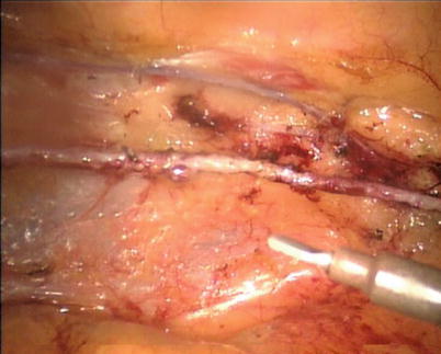
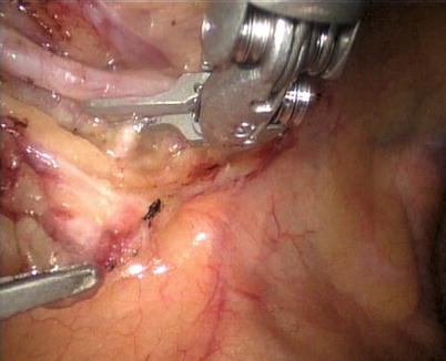
Fig. 8.40
LITA is fully harvested in a skeletonized fashion
Fig. 8.41
Large intercostal branches are clipped using hemoclip