Principles of Pacemaker—Myocardial Interaction
Permanent Pacemaker–Myocardial Interaction
The interaction between the pacemaker generator lead and the living body leads to complex interactions; a simplified explanation of some of the interactions are given in this chapter.
Polarization Resistance
Resistance is opposition to the flow of electric current, and one aspect of cardiac pacing that often confuses the beginner is that resistance or impedance is not static during a pacemaker spike; the resistance increases with time. The rise of polarization resistance with time occurs because electricity is being conducted through a wire, through an electrolyte solution (i.e., the body), and then back through another wire. The tip of a bipolar wire is negatively charged and the ring or band electrode is positively charged. Positive ions in the electrolyte solution begin to travel toward the negatively charged metal surface and negative ions in the solution travel toward the positive electrode. This polarization effect resists the flow of electricity through the circuit. The longer the current is turned on, the greater is the extent of polarization (as shown in Fig. 3-1); hence, the polarization resistance increases with time. When the electricity is turned off, these polarized ions are apart for a brief period, and as they “re-mix” a transient current called after-potential is created—in effect, the polarization has created a brief “battery” with separation of the positive and negative ions.
The polarization effect becomes less prominent as the area of exposed metal surface increases. This inverse relationship explains why the impedance in a unipolar pacemaker is lower than in a bipolar pacemaker. Although in the unipolar system, electricity must travel a longer distance through the
body, the electrolyte solution that comprises intracellular and extracellular fluid is a good conductor of electricity and is not a major source of resistance. The distal electrode tips are small in both the unipolar and bipolar systems; however, the large exposed metal plate of the unipolar anode (as opposed to the small surface area of the bipolar band anode) causes the polarization resistance to be lower in the unipolar system.
body, the electrolyte solution that comprises intracellular and extracellular fluid is a good conductor of electricity and is not a major source of resistance. The distal electrode tips are small in both the unipolar and bipolar systems; however, the large exposed metal plate of the unipolar anode (as opposed to the small surface area of the bipolar band anode) causes the polarization resistance to be lower in the unipolar system.
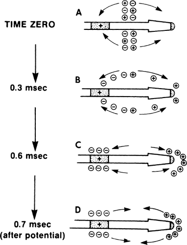 Figure 3-1 Polarization Resistance and After-Potential. A,B: At the beginning of the pacemaker spike, ions have not migrated to the oppositely charged metal surface in any significant number. C: By the end of the 0.6-msec spike, the polarization of the ions has progressed, and the buildup of oppositely charged ions at the metal electrodes opposes the flow of electricity through the circuit and increases resistance (impedance) with time. D: Once the pacemaker spike ends, these polarized ions cause a small sensed current (after-potential) as they mix and become electrically neutral. |
As discussed in Chapter 2, the smaller the electrode tip, the more concentrated the electric charge. With more concentrated charge, the heart muscle can be stimulated with lower energy levels. If this were the only consideration, the smallest tip would be the best; in fact, electrode tips are now much smaller than they were initially. If an electrode tip is made too small, however, the increase in polarization resistance becomes a problem, especially with sensing. In sensing, the electricity generated by the heart itself must travel through the pacemaker circuit to be sensed; because the signal generated is a fairly weak one, its further attenuation by polarization resistance may result in nonsensing. Present-day pacemaker electrodes have exposed metal pacing
tips that are as small as practical to permit maximum charge concentration without causing sensing problems.
tips that are as small as practical to permit maximum charge concentration without causing sensing problems.
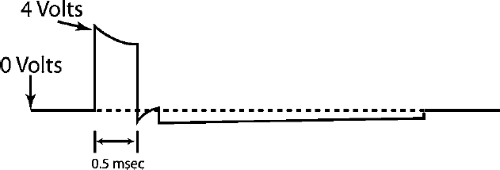 Figure 3-2 Low Intensity Reversible Charge. This figure depicts a low intensity reversible charge between the anode and capillary, just after the pacemaker spike. This is a very low voltage charge for a few milliseconds and is energy independent. It reduces electrolytic coating of the exposed metal in the pacemaker leads. This is really of interest only to emphasize the complexity of designing a metal–tissue interaction that must be functional for years. This is an event that is completely invisible to the patient and the clinician. |
A subtle feature of pacemaker technology, related to polarization resistance, is that there is a recharge. This allows a reversal of charge between the anode and cathode just after the pacemaker spike. This is a very low voltage charge for about 10 msec; it is done by “shorting out” the anode and cathode, and it is not energy dependent. A recharge basically leads to a very low voltage for about 10 msec (much longer than the pacer spike itself, but at a much lower voltage) (Fig. 3-2). This reduces electrolytic coating of the exposed metal in the pacemaker leads. Recharging is essentially invisible to the patient and the physician following the patient and is mentioned only as an example of one of the complex problems that pacemaker engineers face in designing a functional device capable of years of metal–living tissue interaction.
Constant-Voltage and Constant-Current Pacing
Most permanent pacemakers are constant-voltage pacemakers because the voltage remains fairly constant throughout the pacemaker spike. In practice, no permanent pacemaker can maintain an exactly even voltage throughout the pacing spike. Voltage at the leading edge of the spike is higher than at the trailing edge because the capacitor in the pacemaker is necessarily small and cannot store a charge large enough to maintain a strictly constant voltage (this drop in voltage is referred to as tilt and is of greater clinical importance in implantable cardioverter defibrillators). Because of this limitation, the more accurate term constant-voltage capacitor-coupled pacemaker is sometimes used. Figure 3-3 compares a constant-voltage spike with a constant-voltage capacitor-coupled spike and Figure 3-4 describes a single constant-voltage capacitor-coupled pacemaker spike in terms of typical charges in voltage, impedance, and current.
Another type of pacemaker is the constant-current pacemaker, which is designed to provide a constant current despite variation in impedance. As impedance rises, voltage is increased to maintain a constant current. (Again recall that according to Ohm’s Law, V = iR.) The increase in voltage to
maintain a constant current in the face of rising impedance is limited by the voltage capacity of the pacemaker. For example, a pacemaker programmed to deliver a current of 10 mA with a 5 V battery could maintain a constant current of 5 mA only if the impedance of the system remained below 500 ω. Once impedance rises above 500 ω, the battery simply generates its maximum power of 5 V and acts like a constant-voltage pacemaker. Because of
this limitation, the more accurate term constant-current voltage-limited pacemaker is used often (Fig. 3-5).
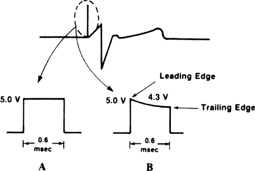 Figure 3-3 Pacemaker Spike. A: True constant-voltage pacemaker spike (not present in implantable permanent pacemaker). B: Constant-voltage capacitor-coupled spike. The spike is seen on the surface electrocardiogram (ECG) as a thin line, but when magnified on an oscilloscope, it has a precise time duration or width (in this case, 0.6 msec) and voltage. The changes in pulse duration that are programmable cannot be detected on a routine ECG and require a special device to be measured. The voltage drop in the spike labeled B occurs because the energy is being delivered from a capacitor discharge and a constant voltage cannot be maintained by the capacitor. |
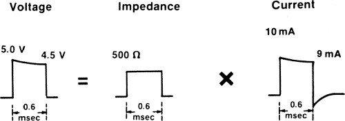 Figure 3-4 Constant-voltage Capacitor-Coupled Pacemaker Spike. The changes in voltage, impedance, and current are shown for a single pacemaker spike. Note the slight drop in voltage from leading edge to trailing edge in the pacemaker spike. The impedance stays relatively constant in this example. Because of the drop in voltage, the current also drops from 10 mA at the beginning of the spike to 9 mA at the end of the spike. (a small, transient, negative current is seen on the current spike because of after-potential; see Fig. 3-1.) |
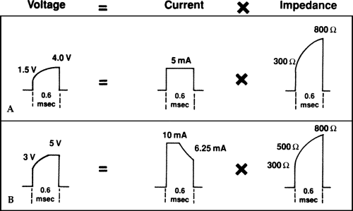 Figure 3-5 Constant-Current Voltage-Limited Pacemaker Spike. A: An idealized constant-current pacemaker with a 5-V battery is set to operate at 5 mA. Over the impedance range shown, the pacemaker acts like a true constant-current source. B: The same 5-V pacemaker is set to operate at 10 mA. Once the impedance reaches 500 ω, the pacemaker is using the entire 5-V battery energy and cannot raise the voltage any higher; from that point on, it acts like a constant-voltage pacemaker. |
Constant-current pacing in the past was used in some permanent pacemakers and it is used in almost all external pacemakers for temporary pacing. The power source of most external pacemakers supplies approximately 15 V; so a true constant current can be maintained in the face of considerable increases in impedance. Batteries in these temporary pacemakers are fairly large and have a short life span compared with those in permanent pacemakers, but neither size nor life span is a major consideration in temporary pacemakers.
Determination of Threshold
The threshold in cardiac pacing is the minimal electric stimulus required to cause cardiac muscle contraction. Having made that general statement, an accurate description of threshold is more complex.
Voltage and Current Threshold
Voltage threshold is the most commonly used measurement of pacing threshold. The pacing wire is placed in contact with the myocardium and connected to a commercially available pacing system analyzer that provides a constant-voltage
power source. A specific pulse width is set (usually the pulse width of the permanent pacemaker to be used, such as 0.4 to 0.6 msec), and the rate of the pacemaker is set high enough to override the patient’s intrinsic heart rate. The voltage is set high enough to stimulate the heart, and then turned down until capture is lost (i.e., until the voltage is too low to stimulate the heart). The lowest voltage that stimulates the heart is the voltage threshold for that given pulse width. The current also can be measured in a similar manner to determine its threshold. There are two types of analyzers: one measures voltage and current at the beginning of the pacemaker spike and the other measures voltage and current at the middle of the pacemaker spike. Thus, slightly different values may be found for the same patient.
power source. A specific pulse width is set (usually the pulse width of the permanent pacemaker to be used, such as 0.4 to 0.6 msec), and the rate of the pacemaker is set high enough to override the patient’s intrinsic heart rate. The voltage is set high enough to stimulate the heart, and then turned down until capture is lost (i.e., until the voltage is too low to stimulate the heart). The lowest voltage that stimulates the heart is the voltage threshold for that given pulse width. The current also can be measured in a similar manner to determine its threshold. There are two types of analyzers: one measures voltage and current at the beginning of the pacemaker spike and the other measures voltage and current at the middle of the pacemaker spike. Thus, slightly different values may be found for the same patient.
In determining threshold, both the voltage and current thresholds can be measured and the impedance of the pacing system should be calculated. Because the permanent pacemaker has a battery with limited voltage, the voltage threshold is the most clinically useful to report. Table 3-1 gives the usually obtainable and acceptable acute (at initial implant) and chronic thresholds and sensing values. Note that the maximum acceptable acute threshold at implant provides a safety margin to allow for the expected chronic threshold rise as well as other changes (such as higher threshold during sleep).
Stay updated, free articles. Join our Telegram channel

Full access? Get Clinical Tree


