Implantable Cardioverter Defibrillator and Antitachycardia Pacing
Permanent Pacing in Combination with an ICD
The implantable cardioverter defibrillator (ICD), an electric device which includes a pacemaker, has undergone revolutionary changes. Although the device initially was developed only to defibrillate patients with ventricular tachycardia or ventricular fibrillation, who did not respond to antiarrhythmic drug therapy, all current models are able to provide defibrillation, low-energy cardioversion, antitachycardia pacing for ventricular tachycardia termination, and bradycardia pacing backup.
An ICD is similar to a pacemaker in that it also is an electric circuit requiring a closed loop. When the ICD shocks the heart, electricity is directed across a large portion of the myocardium to depolarize most of the ventricle, thereby allowing an organized rhythm to return.
Indications
ICDs were originally implanted for circumscribed indications, such as a survivor of a cardiac arrest, but additional studies have greatly expanded the indications. The problem encountered clinically is that patients suffer sudden cardiac death without warning symptoms. Currently the majority of these devices are placed “prophylactically” in patients who are at high risk for sudden cardiac death. This is basically defined by significant left ventricular dysfunction, currently focused on patients with ejection fraction less than 36%. The symptoms of congestive heart failure are required in patients with nonischemic cardiomyopathy (at least Class II, New York Heart Association.) Future efforts at refining the indications will include trying to refine the indications to minimize the number of these expensive devices that are placed prophylactically, and then end up not
being used. Although the vast majority of ICDs are placed for left ventricular dysfunction, there are some clinical indications for ICDs in the setting of good LV function. This can be in a patient at risk for sudden cardiac death with hypertrophic cardiomyopathy, a symptomatic patient with a strong family history of sudden death, or certain patients with long QT syndrome.
being used. Although the vast majority of ICDs are placed for left ventricular dysfunction, there are some clinical indications for ICDs in the setting of good LV function. This can be in a patient at risk for sudden cardiac death with hypertrophic cardiomyopathy, a symptomatic patient with a strong family history of sudden death, or certain patients with long QT syndrome.
Generator
Today, ICD generators are similar in size to the original pacemakers and can now be placed within the chest wall (the original ICDs could be placed only within the abdominal wall because of their size). The largest components of the generator are the capacitor and the battery. Ongoing research is working to miniaturize capacitors. ICDs are usually placed in the pectoral region, allowing the procedure to be performed in the catheterization laboratory.
The battery used in the ICD is usually lithium silver vanadium oxide (rather than the lithium iodine pacemaker batteries), which allows rapid discharge into a capacitor for the frequent rapid shocks that may be required of the ICD device. Longevity is currently often estimated to be 4 years, depending on the frequency of use.
Leads
A simplified picture of the ICD lead is shown in Figure 9-1. The leads are available for rate sensing, pacing, and shocking.
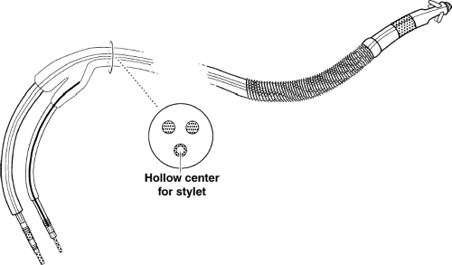 Figure 9-1 Automatic Implantable Cardioverter Defibrillator (ICD). This is a schematic diagram of a cardioverter defibrillation lead. The stippled areas represent exposed metal. The distal two areas of exposed metal of the lead represent the bipolar pacemaker. There is a tip and band electrode, as in a typical bipolar pacemaker. The more proximal larger exposed metal is a coiled metal band that is one pole of the defibrillator. This connects back up to the defibrillator generator. A comparatively large charge of electricity can flow between this pole and the wall of the defibrillator itself, which represents the other pole (through an internal connection to the defibrillator battery). The leads are encased in silicone and separated from each other. One of the pacemaker leads will have a hollow center to allow for a stiffer stylet to be placed through to assist the clinician in placing the lead transvenously. |
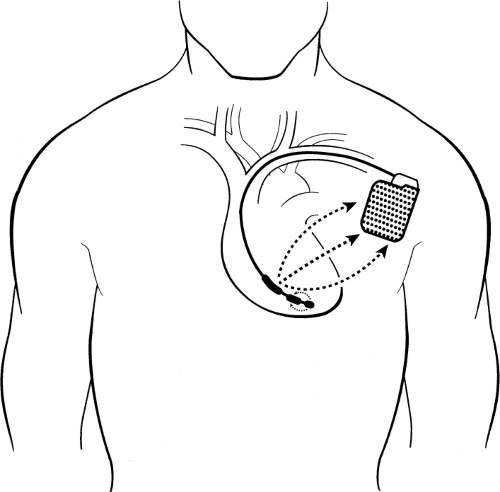 Figure 9-2 Single-lead Pacing Defibrillator Device. In this schematic of a single-lead pacing defibrillator device, the larger arrows demonstrate a shock with electricity flowing between the large proximal band and the wall of the can, which represents the other pole. The generator is usually placed in the left anterior chest, which allows more of the electricity to go through the left ventricle in an effort to defibrillate it. The tip and band electrode of the bipolar pacemaker are shown with a separate electric current available for pacing (of course, the shock and the pacing will not be simultaneous). This is shown schematically for simplification. Figure 9-1 shows a more detailed view of the lead. Also, commonly, dual-chamber pacemakers are used to pace in both the atrium and ventricle. This is not shown again for simplicity’s sake. The addition of an atrial lead, however, allows not only pacing of the atrium but also sensing of atrial activity to improve the accuracy of diagnosis of ventricular tachycardia as opposed to supraventricular tachycardia. |
The lead shown would be placed in the right ventricle and would provide continuous sensing of the ventricular rate (the original, fundamental criteria for detection of sustained ventricular tachyarrhythmias). The current systems incorporate both therapy and rate-sensing function to a single transvenous endocardial lead for simplicity. The bipolar lead can pace in the ventricle and sense the ventricular rate, and the shocking portion of the lead can provide a large electric charge between the coil and generator (Fig. 9-2).
For the sake of simplicity, we have not diagrammed the more complex systems that also incorporate an atrial lead. The atrial lead can be used to count atrial beats (the comparison of atrial beats in relation to ventricular beats can be helpful in deciding whether a rhythm is ventricular tachycardia or supraventricular tachycardia). For instance, with ventricular tachycardia and complete atrioventricular (AV) disassociation, the atrial rate would be
lower than the ventricular rate. If the patient is in supraventricular tachycardia with 1:1 or 2:1 conduction, that information may be useful in determining the exact nature of the arrhythmia. This is a complex area and requires an electrophysiologist to make programming decisions.
lower than the ventricular rate. If the patient is in supraventricular tachycardia with 1:1 or 2:1 conduction, that information may be useful in determining the exact nature of the arrhythmia. This is a complex area and requires an electrophysiologist to make programming decisions.
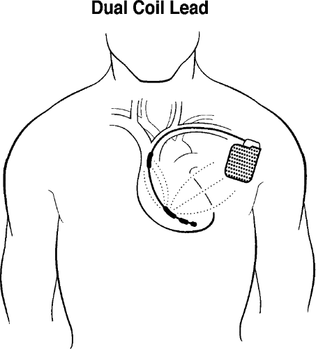 Figure 9-3 Dual Coil Lead. This figure demonstrates the presence of a dual coil, which is the most commonly used device now. In this case the generator as well as the proximal (superior vena cava) coil are both active. The charge is dispersed from the distal coil to the more proximal coil as well as to the generator. This greater dispersion of the charge generally allows more of the ventricular myocardium to be depolarized at once, making the device more effective in terminating ventricular fibrillation. |
Current leads are generally dual coil; the generator and the proximal coil have the same polarity. Electricity flows in a three-dimensional configuration from the distal coil to both the proximal coil and generator (Fig. 9-3). This greater dispersion of the electrical field increases the likelihood of depolarizing the entire ventricular myocardium at once, leading to successful defibrillation.
Sensing
Sensing in an ICD is a much more complicated issue than in a pacemaker. In a pacemaker, the device has to sense only the QRS complexes, and avoid sensing T waves. In the ICD, the sensing circuit must be dynamic. It must
sense and count QRS complexes appropriately (and avoid “double counting” by sensing the T wave, which can lead to inappropriate electrical therapy). The device must, in addition, be able to become more sensitive after sensing the QRS complex so that if ventricular fibrillation occurs, it can sense the defibrillatory waves. The device also must be programmable to deal with sensing problems.
sense and count QRS complexes appropriately (and avoid “double counting” by sensing the T wave, which can lead to inappropriate electrical therapy). The device must, in addition, be able to become more sensitive after sensing the QRS complex so that if ventricular fibrillation occurs, it can sense the defibrillatory waves. The device also must be programmable to deal with sensing problems.
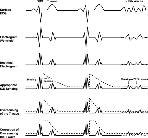 Figure 9-4 ICD Sensing. At the top is the surface ECG demonstrating the QRS and T wave and the onset of ventricular fibrillation. The second line demonstrates the electrogram as sensed by the pacemaker (this is the ventricular lead so the P wave does not play a role in sensing unless there is some problem with the device). The rectified electrogram simply is the same picture with negative portions made positive by the ICD device. The fourth line demonstrates appropriate ICD sensing. The QRS is sensed. At that point the sensing threshold is raised suddenly and significantly (it becomes less sensitive) and then it gradually falls down. This avoids sensing the T wave inappropriately, but it falls down to a baseline fairly soon so that ventricular tachycardia or even small ventricular fibrillation waves can still be sensed. The fifth line indicates inappropriate oversensing of the T wave. This would lead to “double counting” and a normal sinus rate of 90 bpm could be sensed as a tachycardia at 180, leading to tachypacing or even a shock. The sixth and bottom line demonstrates correction of oversensing of the T wave. In this case there is about a 30 msec extension of poor sensitivity (a higher threshold for sensing) that allows the ICD to not sense the T wave, but still fall down gradually and sense ventricular fibrillation waves. Various devices have different ways of handling this potential problem; for instance, the height rise after QRS sensing can simply be raised even higher so that when the sensitivity increases, the T wave is missed. Note that it is very important to always fall to a level that ventricular fibrillation waves can be sensed. Not sensing ventricular fibrillation waves can lead to death. |
Early in the cardiac cycle the greatest problem is generally oversensing of the T wave. Later in the cardiac cycle, as the device becomes more sensitive (a sensing threshold is much closer to baseline), there are occasional episodes of oversensing of diaphragmatic myopotentials (this is a less common problem, however, than oversensing of the T wave). Multiple programs are available to help solve these difficult issues and the implanter must be aware of the complexity and be able to troubleshoot problems. Figure 9-4 gives a hypothetical example of a sensing program.
Basic System Operation
The operation of the ICD is similar to that of the pacemaker in that the two basic functions are sensing and delivering electricity. ICDs can be traced back through three generations of development. The first devices could detect ventricular tachycardia (VT) or ventricular fibrillation (VF) and, after a certain elapsed period, charge the capacitor and deliver a nonprogrammable, nonsynchronized shock of 25 to 30 joules (J), up to a maximum of five consecutive times unless the tachycardia was terminated. The second generation of devices provided programmable low-energy cardioversion in addition to the conventional high-energy shocks. The third and present generation of ICDs features what is referred to as tiered therapy, which includes antitachycardia pacing for painless termination of monomorphic VT, programmable low-energy cardioversion, high-energy defibrillation, and backup bradycardia pacing. Figure 9-2, shown earlier, demonstrates the concepts of shocking and pacing. The large proximal electrode is one pole and the metallic covering of the generator is the other pole. This represents the large shock for defibrillation or cardioversion from rapid tachycardia. The tip and band electrode of the typical pacing lead are shown with small dots indicating the potential for pacing (of course, they would not be pacing and shocking at the same time).
In addition, ICDs have the ability to perform noninvasive electrophysiologic (EP) testing and are able to store electrograms after a shock has occurred, therefore assisting the physician in identifying types and numbers of therapies delivered when the patient returns for checkups. The tiered therapy devices have proven beneficial and more acceptable in patients who can be converted out of their tachycardia by painless pacing or low-level cardioversion rather than the more painful defibrillation. In a tiered device, however, if the tachycardia is not converted with these lower-energy therapies after a preprogrammed period, cardioversion or defibrillation is initiated (Table 9-1).
TABLE 9-1 Tiered therapy | ||||||
|---|---|---|---|---|---|---|
|
Tachycardia Detection
The fundamental way that the ICD identifies the presence of a sustained ventricular tachyarrhythmia is by detecting that the heart rate has exceeded a critical value as measured in the ventricle. Because most episodes of sustained VT exhibit a rate in excess of 150 beats per minute (bpm), the device can be programmed to initiate therapy when this rate (or another rate based on individual patient characteristics) is reached. Programming decisions regarding tiered therapy must take into account the hemodynamic status of the patient during the tachyarrhythmia episode. For antitachycardia pacing, additional detection criteria may be programmed to enhance the certainty that a ventricular tachyarrhythmia is present rather than a supraventricular tachyarrhythmia (SVT), often atrial fibrillation. Such detection enhancements include the identification of cycle length stability, the abruptness of onset of the tachyarrhythmia, morphology analysis, and the duration of a sustained rate. As mentioned earlier, the dual-chamber ICD allows counting of atrial rates in comparison to ventricular rates. For instance, if the ventricular rate is greater than the atrial rate, the ICD can be programmed to treat without regard to SVT discriminators. This will often require an electrophysiologist for follow-up; for example, there is a risk of ventricular tachycardia leading to retrograde VA conduction and 1:1 relation of ventricular and atrial rates, mimicking a SVT.
The morphology of the electrogram as measured by the device may also be used to differentiate supraventricular tachycardia versus ventricular tachycardia (current devices are now more reliable than the original efforts in this area).
Therapy Tiers
Because VF often manifests as rates in excess of 240 bpm, the ICD may be programmed to respond to such rates by defibrillation. With tiered therapy devices, rate ranges can be programmed that determine the type of therapy to
be delivered. Thus, with rates of 150 to 240 bpm, antitachycardia pacing or low-energy cardioversion can be used; for rates greater than 240 bpm, defibrillation may be the programmed response. The rates that dictate the type of therapy can be tailored to the individual patient.
be delivered. Thus, with rates of 150 to 240 bpm, antitachycardia pacing or low-energy cardioversion can be used; for rates greater than 240 bpm, defibrillation may be the programmed response. The rates that dictate the type of therapy can be tailored to the individual patient.
Bradycardia Pacing
Often patients successfully converted out of VT or VF are found to have marked sinus bradycardia immediately postconversion, posing another threat to hemodynamic stability. Therefore, modern ICD devices often have the option of VVI pacing, DDD pacing, DDDR pacing, AAI pacing, and AAIR pacing. After a shock, the threshold required to pace may increase. Therefore, as a precaution, a higher output can be programmed for several beats after the shock.
Antitachycardia Pacing
Many episodes of VT are amenable to termination by a technique known as overdrive pacing, which is based on the observation that the mechanism of VT involves reentry, a circulating wavefront of excitation within a discrete region of myocardium. Between the leading edge of the wavefront and the tail of refractoriness, just ahead of the circulating wavefront is a region known as the excitable gap, which represents a segment of excitable myocardial tissue about to be depolarized by the propagating wavefront; thus, it circulates with the wave of excitation. If a critically timed premature impulse (or train of paced impulses) arrives at the site of reentry such that the impulse invades the circuit when the excitable gap permits, the circus movement will be terminated abruptly because of the collision of the two wavefronts (Fig. 9-5). Because a train of rapidly paced impulses increases the probability of invasion of the excitable gap, antitachycardia pacing usually uses a burst of ventricular paced impulses. Antitachycardia pacing is often indicated as first-line treatment in patients with VT under 240 bpm (although a lower limit may be required in some patients). For many patients, this rate of ventricular tachycardia may be reasonably hemodynamically stable and thus provide the opportunity for a form of therapy that is painless and requires less current drain (e.g., tachypacing instead of shocking). Therefore, pacing for termination may be effective and more desirable from a comfort standpoint and for preservation of the battery. When this form of therapy is programmed, initial response to tachycardia will be a burst of pacing impulses delivered at a rapid rate. Up to 15 paced impulses per burst may be delivered at a time (a common number used is about 8 impulses per burst). Different modes of tachypacing delivery may be built into devices from different manufacturers.
Stay updated, free articles. Join our Telegram channel

Full access? Get Clinical Tree


