6 Power Systems for Implantable Pacemakers, Cardioverters, and Defibrillators
 Batteries
Major Components Of Batteries
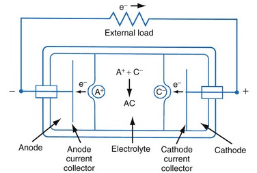
Figure 6-1 shows a simple battery; the major parts are the anode, cathode, and electrolyte. The anode and cathode must be physically separated, and both must be in contact with the electrolyte.
Functional Characteristics Of Batteries
Capacity
The fundamental unit of battery capacity is the coulomb (C), or ampere-second (A-sec). This is the amount of charge delivered by one ampere (1 A) of current in 1 second. In the context of implantable devices, it is customary to express battery capacity in terms of ampere-hours (A-hr), which represents the charge carried by a current of 1 A flowing for 1 hour; 1 A-hr = 3600 C. A battery for an implantable medical device usually has a capacity rating of  to 2 A-hr. The methods for determining and specifying the capacity of a medical battery produce numbers ranging from upper-limit theoretical values that can never be achieved in the field to realistic values based on detailed models or accelerated testing.1–3 More sophisticated methods account for limited availability of the components within the battery, kinetic limitations on the chemical reaction, and losses to side-reactions over time.
Estimating the deliverable capacity of implantable medical batteries is especially difficult because of their long service life. The time frame for the operation of most implantable medical devices is so long (5-10 years) that real-time measurements of capacity are not practical. Therefore, accelerated tests and models are typically used to estimate the amount of deliverable capacity in these batteries. Technology in this area is now highly developed, and it is possible to make highly accurate projections of deliverable battery capacity under a range of usage conditions.4–6
Cell Voltage and Current
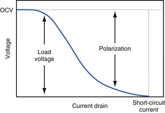
The open-circuit voltage of a battery can be calculated from the thermodynamic free energy for the discharge reaction. This is the voltage that will be measured when there are no kinetic limitations, a condition that occurs only when an insignificant amount of current is being drawn from the battery. With the onset of current flow, the voltage at the battery terminals will be smaller than the open-circuit value. Both chemistry and battery design determine the relationship between voltage and current drawn from the battery. For example, a lead-acid battery for automotive use is constructed of very conductive materials and is designed with large-surface-area electrodes so that extremely high currents can be drawn from it to run an engine’s starter motor. On the other hand, a transistor radio battery is designed with small electrodes because relatively low currents are typically needed to power small portable electronic devices. Figure 6-2 shows a typical current-voltage relationship in which the load voltage approaches the open-circuit voltage (OCV) as the current approaches zero. At the other extreme, the maximum (short-circuit) current is observed when the load voltage approaches zero.
Non-Ideal Battery Behavior
Polarization
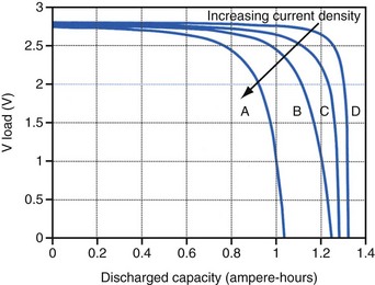
Polarization is any process that causes the voltage at the terminals of a battery to drop below its open-circuit value when it is providing current. The internal resistance of the battery is one important cause. This is well illustrated in Figure 6-3 for the lithium/iodine battery, but the same is true for all batteries to some degree. The differences in the curves for discharge voltage versus capacity at four rates of constant current discharge are mainly caused by the voltage drop associated with internal resistance of the battery. Other contributing elements of voltage loss when a battery provides current are concentration polarization, which is associated with concentration gradients that may develop in the electrolyte or the active electrode materials, and activation polarization, which is associated with the kinetics of the electron-transfer reactions at the electrode/electrolyte interfaces.
Self-Discharge
Self-discharge is the spontaneous discharge of a cell or battery by an internal chemical reaction rather than through useful electrochemical discharge. We have all seen the effects of self-discharge, such as the flashlight that does not work when needed after prolonged storage. One mechanism of self-discharge involves a slow, direct reaction between the anode and cathode; for example, if one or both of the active electrode materials are slightly soluble in the electrolyte. Other self-discharge processes may involve reactions between anode or cathode and another substance in the battery, such as the solvent in the electrolyte; for example, the typical reaction between the anode and the electrolyte solvent to form a passive film on the lithium anode or a gas that pressurizes the battery case. These parasitic reactions are usually very slow, but because medical batteries are expected to operate for many years, their accumulated effects can be appreciable. Although it is difficult to measure the very slow rate of self-discharge reactions, techniques such as microcalorimetry can detect the small amounts of heat involved.7,8 The heat generated can be used to calculate the rate of self-discharge by applying thermodynamic principles. Accurate assessment of self-discharge is an important element in predictive models of battery performance used in both device design and longevity estimation.
Batteries in Implantable Cardiac Rhythm Management Devices
Size, Energy Density, and Current Drain
The relationship between battery size and average current is not one of direct proportionality. For example, decreasing the average current by 50% will not permit a 50% reduction in battery size without compromising longevity because of the inactive materials in a battery (e.g., case, electrolyte, current collectors). Likewise, the usable energy density is also a function of the current demand on the cell. As the current from the cell is increased, the resulting voltage drops significantly (see Fig. 6-3), which reduces the time during which the cell can provide current at or above the minimum voltage necessary to operate the electronic circuits. Thus, usable energy density, which is directly proportional to the area under the discharge (voltage vs. capacity) curve, is also reduced. For very-high-rate batteries such as those used to power ICDs, this is not such an issue because their internal resistance is extremely low.
The Battery and Longevity of Pulse Generator
Effect of Pulse Width on Pacing Current
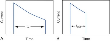
Increasing the pacing rate, pulse width, or pulse amplitude increases the average pacing current. The average pacing current, excluding static current, is directly proportional to the pacing rate. Recall that the pacing pulse results from the discharge of a capacitor through the electrode-heart interface. This capacitor produces a pulse in which the current decays exponentially with time, as shown for two different pulse widths in Figure 6-4.
where VA is the amplitude at the beginning of the pacing pulse, RH is the impedance of the lead plus the heart (discussed later), C is the value of the capacitor that delivers the pacing pulse, and t is the time since the beginning of the pacing pulse. In Figure 6-4, A and B, the pulse width is tw and tw/2, respectively. The area under each current-time curve gives the total charge delivered during the pulse. Although the width of the pulse in B is half that of the pulse in A, the charge delivered by this pulse is considerably more than half that of the longer pulse. The exact ratio of the charge delivered in the two cases depends on the values of RH and C. Nevertheless, reducing the pulse width by a given fraction will always reduce the average pacing current by a substantially smaller fraction because of the exponentially decaying shape of the pacing stimulus current curve.


