Class I
Permanent pacemaker implantation is indicated for:
1. third-degree and advanced second-degree AV block at any anatomic level associated with bradycardia with symptoms (including heart failure) or ventricular arrhythmias presumed to be due to AV block (Level of Evidence: C)
2. third-degree and advanced second-degree AV block at any anatomic level associated with arrhythmias and other medical conditions that require drug therapy that results in symptomatic bradycardia (Level of Evidence: C)
3. third-degree and advanced second-degree AV block at any anatomic level in awake, symptom-free patients in sinus rhythm, with documented periods of asystole greater than or equal to 3.0 s or any escape rate less than 40 bpm, or with an escape rhythm that is below the AV node (Level of Evidence: C)
4. third-degree and advanced second-degree AV block at any anatomic level in awake, symptom-free patients with AF and bradycardia with 1 or more pauses of at least 5 s or longer (Level of Evidence: C)
5. third-degree and advanced second-degree AV block at any anatomic level after catheter ablation of the AV junction (Level of Evidence: C)
6. third-degree and advanced second-degree AV block at any anatomic level associated with postoperative AV block that is not expected to resolve after cardiac surgery (Level of Evidence: C)
7. third-degree and advanced second-degree AV block at any anatomic level associated with neuromuscular diseases with AV block, such as myotonic muscular dystrophy, Kearns-Sayre syndrome, Erb dystrophy (limb-girdle muscular dystrophy), and peroneal muscular atrophy, with or without symptoms (Level of Evidence: B)
8. second-degree AV block with associated symptomatic bradycardia regardless of type or site of block (Level of Evidence: B)
9. asymptomatic persistent third-degree AV block at any anatomic site with average awake ventricular rates of 40 bpm or faster if cardiomegaly or LV dysfunction is present or if the site of block is below the AV node (Level of Evidence: B)
10. second- or third-degree AV block during exercise in the absence of myocardial ischemia (Level of Evidence: C)
Class IIa
Permanent pacemaker implantation is reasonable for:
1. persistent third-degree AV block with an escape rate greater than 40 bpm in asymptomatic adult patients without cardiomegaly (Level of Evidence: C)
2. asymptomatic second-degree AV block at intra- or infra-His levels found at electrophysiological study (Level of Evidence: B)
3. first- or second-degree AV block with symptoms similar to those of pacemaker syndrome or hemodynamic compromise (Level of Evidence: B)
4. asymptomatic type II second-degree AV block with a narrow QRS. When type II second-degree AV block occurs with a wide QRS, including isolated right bundle branch block, pacing becomes a Class I recommendation (Level of Evidence: B)
Class IIb
Permanent pacemaker implantation may be considered for:
1. neuromuscular diseases such as myotonic muscular dystrophy, Erb dystrophy (limb-girdle muscular dystrophy), and peroneal muscular atrophy with any degree of AV block (including first-degree AV block), with or without symptoms, because there may be unpredictable progression of AV conduction disease (Level of Evidence: B)
2. AV block in the setting of drug use and/or drug toxicity when the block is expected to recur even after the drug is withdrawn (Level of Evidence: B)
Class III
Permanent pacemaker implantation is not indicated for:
1. asymptomatic first-degree AV block (Level of Evidence: B)
2. asymptomatic type I second-degree AV block at the supra-His (AV node) level or that which is not known to be intra- or infra-Hisian (Level of Evidence: C)
3. AV block that is expected to resolve and is unlikely to recur (e.g., drug toxicity, Lyme disease, or transient increases in vagal tone or during hypoxia in sleep apnea syndrome in the absence of symptoms) (Level of Evidence: B)
Table 30.2
NASPE/BPEG classifications for pacing and defibrillation systems
I | II | III | IV |
|---|---|---|---|
Chamber(s) paced | Chamber(s) sensed | Response to sensing | Programmability/rate modulation |
O = none | O = none | O = none | O = none |
A = atrium | A = atrium | T = triggered | P = simple programmability |
V = ventricle | V = ventricle | I = inhibited | M = multiparameter programmability |
D = dual (A + V) | D = dual (A + V) | D = dual (T + I) | C = communication with programmer R = rate modulation |
Table 30.3
Pacing and timing abbreviations
AP = Atrial pace |
VP = Ventricular pace |
AS = Atrial sense |
VS = Ventricular sense |
AR = Atrial refractory event |
VR = Ventricular refractory event |
AEI = Atrial escape interval—longest allowable interval between ventricular and atrial event (also called VA interval) |
ARP = Atrial refractory period |
AV = Atrioventricular |
AV interval = Longest allowable interval between atrial and ventricular event |
LR = Lower rate—slowest pacing rate allowed |
LR interval = Longest period of time allowed before delivery of a pacing stimulus |
MS = Mode switch |
PAV = Paced atrioventricular interval—longest allowable interval between paced atrial beat and paced or sensed ventricular beat |
PMT = Pacemaker-mediated tachycardia |
PVAB = Postventricular atrial blanking period |
PVARP = Postventricular atrial refractory period |
SAV = Sensed atrioventricular interval—longest allowable interval between sensed atrial beat and paced or sensed ventricular beat |
TARP = Total atrial refractory period (AV + PVARP) |
UAR = Upper activity rate (also called maximum sensor-indicated rate) |
UR = Upper rate—fastest pacing rate allowed |
UR interval = Shortest allowable interval between paced beats or a sensed and paced beat |
UTR = Upper tracking rate—fastest rate the ventricles may be paced in 1:1 synchrony with the sensed atrial rate (also called maximum tracking rate) |
VA interval = Time between ventricular and atrial event |
VRP = Ventricular refractory period |
VSP = Ventricular safety pacing |
30.2.2 Conditions of the Sinoatrial Node
Normal sinus rhythm | Sinoatrial nodal rate is appropriate for the current metabolic demand (see online Video 30.1. |
Sinus bradycardia | A slow sinoatrial nodal rate, resulting in a slow heart rate which may or may not be functionally appropriate. HR↓ → CO↓ |
Sinus tachycardia | A fast sinoatrial nodal rate, resulting in a higher heart rate which may or may not be functionally appropriate. HR↑ → CO↑ (for excessive heart rates, CO↓ due to reduced filling time). |
Sick sinus syndrome | Unpredictable sinoatrial nodal rate. The rate is not appropriately coordinated with physiologic demand. CO↑ or CO↓ |
Chronotropic incompetence | Inappropriate response of the sinoatrial node to exercise. CO is too low for metabolic demands. |
Block | No sinoatrial nodal rhythm. The patient will have either no heart rate (asystole) or a rate defined by other regions within the heart. A rescue rhythm from the atrioventricular node normally occurs (40–60 beats per minute, a so-called junctional rhythm). HR = 0 → CO = 0 or HR↓ → CO↓ |
30.2.3 Conditions of the Atrioventricular Node
1st degree heart block | An atrioventricular interval >200 ms (normal atrioventricular interval is ~120 ms). SV↓ → CO↓ |
2nd degree heart block | Atrial and ventricular activity is not 1:1. Two types of 2nd degree block are defined: Mobitz types I and II. |
Mobitz type I: Wenckebach phenomenon. A ventricular beat is dropped after a progressive elongation of the atrioventricular interval. HR↓ (missed beat) → CO↓ | |
Mobitz type II: A ventricular beat is dropped without a progressive elongation of the atrioventricular interval. This is often an early indication of progressive disease of the conduction system. HR↓ (missed beat) → CO↓ | |
3rd degree heart block | No atrioventricular nodal conduction (conduction from the atrium to the ventricles). The atria contract at the sinoatrial nodal rate, and the ventricles are either asystolic or contract at a ventricular rescue rate (40–60 beats per minute). HR↓ and SV↓ → CO↓ |
30.2.4 Arrhythmias
Atrial tachycardia/flutter | High atrial rate of non-sinoatrial nodal origin. Not a physiologic rate, therefore decoupled from metabolic demand (see online Video 30.2). HR↑ SV↓ → CO↑ or CO↓ |
Atrial fibrillation | Chaotic depolarization of the atrium. No atrial hemodynamic input to the ventricles and a nonphysiologic rate is conducted through the atrioventricular node to the ventricles. Ventricular output is decoupled from metabolic demand. Stasis of blood in the atria can result in clot formation and stroke (see online Video 30.3). HR↑ SV↓ → CO↑ or CO↓ |
Ventricular tachycardia | High ventricular rate decoupled from sinoatrial nodal and atrial activity. This commonly results from a reentrant conduction loop or an ectopic foci (spontaneously beating region of myocardium). Ventricular rate is nonphysiologic, therefore decoupled from metabolic demand (see online Video 30.4). HR↑ SV↓ → CO↑ or CO↓ |
Ventricular fibrillation | Chaotic depolarization of the ventricles. No organized heart rate (see online Video 30.5). CO = 0 |
30.3 Introduction to Implantable Pacing and Defibrillation Systems
For proper function and programming, implantable pacing and defibrillation systems require multiple components as well as external instruments. The implantable portion of the system is typically comprised of the implantable pulse generator (IPG, or pacemaker) or an implantable cardioverter defibrillator (ICD, or defibrillator) and the pacing and/or defibrillation leads. The IPG or ICD is most commonly implanted in a subcutaneous location in the left pectoral region. Depending on handedness, the condition of the upper venous system, the presence of other devices, and/or physician/patient preference, the device may also be placed in the right pectoral region. The device may be placed in a submuscular location in situations where the physician is concerned about either erosion of the IPG or ICD through the skin (most common in thin, elderly, or very young patients) or for cosmetic reasons (to reduce the obvious nature of the device). Another variation is to place the device in an abdominal location. This is commonly done in small children to avoid discomfort and/or interference with the motion of the arm and is of course dependent upon device size. This may also be a more practical device location in association with epicardial leads.
In support of the implanted hardware, an external programmer is used to noninvasively telemeter information to and from the programmable IPG. This allows the physician to set/reset parameters within the device and download information relating to the status of the patient and the device. A complete defibrillation system is shown schematically in Fig. 30.1 (pacing systems use a similar configuration).
Fig. 30.1
Schematic of a typical implantable defibrillation system and the associated programmer. ICD implantable defibrillation device
Pacing and defibrillation systems can be implanted using several methods. Early systems used leads attached to the epicardial surface of the heart, with the IPG or ICD placed in the abdomen of the patient (due to their larger sizes). Although this technique is still used in certain clinical situations (i.e., neonates), a transvenous approach for attaching the leads to the heart and a pectoral placement of the IPG or ICD is far more common. The implantation technique for implantable pacing and defibrillation will be described to provide a more thorough understanding of the system requirements.
Following anesthesia and a sterile preparation of the incision site, typically one of two techniques is used to access the venous system for the implantation of transvenous leads. Accordingly, venous access is achieved through either a surgical cutdown to the cephalic vein (the jugular vein is also used, but this is rare) or a transcutaneous needle puncture into the subclavian vein. The cutdown involves a careful surgical dissection down to the vessel, placement of a cut through the vessel wall, and direct insertion of the lead into the vessel lumen. The subclavian puncture uses a needle to puncture the vessel, followed by passage of a guidewire through the needle. Subsequently, an introduction catheter (percutaneous lead introducer) with an internal dilator is forced over the wire and into the vein. The dilator is removed, leaving the catheter behind. The lead is then inserted through the catheter (this Seldinger Technique can be viewed in online Video 30.6).
Following insertion into the vein, the lead(s) are advanced through the superior vena cava and into the right atrium for final placement in the right atrium, right ventricle, and/or the coronary sinus/cardiac veins (providing access to the left atrium and ventricle). Once positioned properly, the leads are secured in the desired location within the heart using either a passive or active means of fixation (see the section on leads). Next, an anchoring sleeve is used at the venous entry site to secure the lead into the vein and the surrounding tissue. This isolates the lead from mechanical forces outside of the vein, ensuring that adequate lead length remains within the heart to accommodate motion due to activity, respiration, and/or heart motion. Following lead implantation, the proximal terminal ends are connected to the IPG or ICD, which is then placed in a subcutaneous or submuscular pocket formed in the tissue. The implant site is then sutured closed, thus completing the implantation. Chest X-rays of a dual-chamber endocardial pacing system are shown in Fig. 30.2, and additional radiographic images of several pacing configurations are found in online JPGs 30.7–30.12.
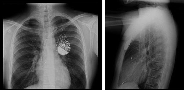
Fig. 30.2
Chest X-rays of an endocardial, dual-chamber pacing system in a young patient (anterior view on the left; lateral view on the right; Sainte-Justine Hospital, Montreal, QC, Canada used with permission). The implantable pulse generator (IPG or pacemaker) is implanted in the left pectoral region. The superior lead is implanted in the right atrial appendage and the inferior lead is in the right ventricular apex
30.4 Cardiac Pacing
30.4.1 History
Discoveries relating to the identification of the electrophysiological properties of the heart and the ability to induce cardiac depolarization through artificial electrical stimulation are relatively recent. Gaskell, an electrophysiologist, coined the phrase heart block in 1882 and Purkinje first described the ventricular conduction system in 1845. Importantly, Gaskell also related the presence of a slow ventricular rate to disassociation with the atria [4]. The discovery of the bundle of His is attributed to its namesake, Wilhelm His Jr. [5]. He described the presence in the heart of a conduction pathway from the atrioventricular node through the cardiac skeleton that eventually connected to the ventricles. Tawara later verified the existence of the bundle of His in 1906 [6]. He is also credited with being the first to clearly identify the specialized conduction tissues (modified myocytes) that span from the atrial septum to the ventricular apex, including the right and left bundle branches and Purkinje fibers.
The first known instance of electrical resuscitation of the heart was by Lidwell in 1929. Further, Hyman produced the first device for emergency treatment of the heart in 1932. Paul Zoll performed the first clinical transcutaneous pacing in 1952. Importantly for the pacing industry, the first battery-powered pacemaker was developed by Earl Bakken and used in postsurgical pediatric patients by C. Walton Lillehei in 1957 at the University of Minnesota (Fig. 30.3) [4, 7, 8]. Also see Chap. 25.
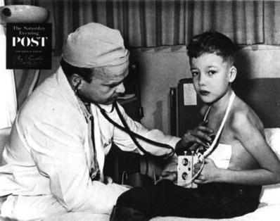
Fig. 30.3
Dr. C. Walton Lillehei with the first battery-powered, wearable pacemaker
30.4.2 Artificial Electrical Stimulation
In addition to the spontaneous contraction that occurs within the heart, artificial electrical stimulus (cardiac pacing) can be used to initiate myocardial contraction. This stimulation, in the form of cardiac pacing, is routinely performed as a means to manage patients with cardiac arrhythmias and conduction abnormalities [9, 10]. Pacing induces myocardial contraction through the delivery of an electrical pulse to the patient’s heart using an IPG and a cardiac pacing lead. The cardiac pacing lead acts as the electrical conduit for both stimulation and sensing, thus interfacing with the myocardial tissue. The electrical pulse is delivered either in a bipolar mode (involving cathodal and anodal electrodes on the lead) or in a unipolar mode (with a cathode on the lead and the metallic housing of the IPG serving as the anode).
To initiate depolarization, an action potential must be created on a given volume of myocardium. As was described in previous chapters, a normal myocardial cell has a resting membrane potential of approximately –90 mV. The resting membrane potential is dominated by the concentration of potassium (K). A cellular action potential occurs when the resting membrane potential is shifted towards a more positive value (i.e., less negative value) to approximately –60 to –70 mV. At this threshold potential, the cell’s voltage-gated Na channels open and begin a cascade of events. In artificial electrical stimulation (pacing), this shift in the resting potential and subsequent depolarization is produced by the pacing system.
Two theories describe the mechanism by which artificial electrical stimulation initiates myocardial depolarization. The Current Density Theory states that a minimum current density (amps/cm3) is required for stimulation of an excitable tissue. The Electric Field Theory requires that a minimum voltage gradient (volts/cm) be produced within the myocardium to initiate depolarization [11]. These two theories can, in part, be considered related, since the passage of current through the tissue (Current Density Theory) will induce a potential difference across the cell membranes due to the limited conductivity of the tissue. Similarly, the creation of a potential within the tissue (Electric Field Theory) will also induce a current. Regardless of the theoretical position taken regarding stimulation, the requirement for artificial stimulation is the shifting of the resting membrane potential from its normal value (typically –90 mV) towards a more positive value, until the depolarization threshold is reached.
The impedance associated with charge transfer from an IPG to the cardiac tissue is comprised of resistive (R) and reactive components (X C = capacitive; X L = inductive):
 The resistive term (R) includes the DC resistance associated with the conductors internal to the lead (R C = cathodic conductor; R A = anodic conductor), the cathode–tissue interface (R CT), the anode–tissue interface (R AT), and the tissue itself (R T):
 The capacitive term (X C) is the sum of the capacitance of the cathode–tissue interface (C CT) and the anode–tissue interface (C AT).
 The inductance within the conductors and circuit is extremely small and this term is typically neglected. Ignoring inductance, the resulting equation for lead impedance is:
 Schematic representations of the circuitry for bipolar and unipolar pacing systems are shown in Figs. 30.4 and 30.5. In these figures, the electric circuit for the delivery of energy to the myocardium is described as a simple RC circuit in which the IPG acts as the voltage/charge source and the lead conductors, electrodes, and cardiac tissue act as the load. Figure 30.4 depicts a bipolar pacing circuit in which the cathode and anode both reside on the pacing lead. Figure 30.5 represents the circuitry associated with a unipolar pacing system. In this case, the circuit is still bipolar but the anode is the metallic housing of the IPG; the term unipolar refers to the polarity of the lead.
Fig. 30.4
Bipolar pacing circuit, including an implantable pulse generator and a pacing lead. Resistances: R C cathodic lead conductor, R CT cathode–tissue interface, R T tissue, R AT anode–tissue interface, R A anodic lead conductor. Capacitances: C CT cathode–tissue interface, C AT anode–tissue interface
Fig. 30.5
A pacing circuit (unipolar type) which includes an implantable pulse generator and a pacing lead. Resistances: R C cathodic lead conductor, R CT cathode–tissue interface, R T tissue, R AT anode–tissue interface. Capacitances: C CT cathode–tissue interface, C AT anode–tissue interface
Typical pacing circuit impedances range from 400 to 1500 Ω. Approximately 80 % of the total impedance is at the tissue interface; as an example, this will result in a 0.8 V drop at the tissue interface when a 1.0 V pacing pulse amplitude is used. Using the aforementioned impedances (400–1500 Ω), a pacing output of 1.0 V produces currents of 2.5 mA and 0.67 mA, respectively.
To date, the most common pacing stimulation waveform used to electrically activate the myocardial tissue is an exponentially decaying square wave. An active recharge is also commonly included at the trailing edge of the stimulation pulse to reduce the post-pace polarization on the electrodes by balancing the charge delivered. The stimulating portion of the waveform is characterized by its amplitude (volts) and width (milliseconds). A relationship exists between the amplitude and pulse width that will be required for depolarization (pacing) of the tissue. This relationship, termed a strength-duration curve is most commonly plotted as shown in Fig. 30.6.
Fig. 30.6
A typical strength-duration curve for cardiac pacing. This particular curve was obtained using a Medtronic model 5076 bipolar pacing lead positioned in the right ventricular (RV) apex of a canine. In this plot, chronaxie and rheobase were 0.5 ms and 0.4 V, respectively
Terminology relating to the strength-duration curve includes the rheobase and chronaxie values. Rheobase is the threshold voltage at an infinitely long pulse width, and chronaxie is the threshold pulse width at two times the rheobase voltage. The output of a clinical IPG is commonly set at twice the voltage threshold corresponding at the chronaxie pulse width, thus insuring a safety margin [11].
30.4.3 Indications for Pacing
Pacing and defibrillation systems are designed to maintain appropriate cardiac rhythms to maximize the patient’s safety and quality of life. With the exception of cases of sudden cardiac death where an external defibrillator is clearly required, the determination of when to use a pacing or implantable defibrillation system can be complex. This section will describe the current classification of indications for pacing and provide a few practical examples of these indications and the decision process associated with choosing the appropriate system for a given patient’s condition.
The indications for either pacing or defibrillation therapies are commonly classified in the standard ACCF/AHA/HRS (American College of Cardiology Foundation/American Heart Association/Heart Rhythm Society) format as follows [2]:
Class I | Benefit >> > Risk. Procedure/treatment should be performed/administered. |
Class II | Conditions for which there is conflicting evidence and/or a divergence of opinion about the usefulness/efficacy of a procedure or treatment. |
Class IIa | Benefit > > Risk. Additional studies with focused objectives needed. It is reasonable to perform procedure/administer treatment. |
Class IIb | Benefit > Risk. Additional studies with broad objectives needed; additional registry data would be helpful. Procedure/treatment may be considered. |
Class III | Classified as “No benefit” (Procedure/test is not helpful with no proven treatment benefit) or “Harm” (Procedure/test is associated with excessive cost without benefit or is harmful and the treatment is harmful to the patient). |
For each classification listed above, a Level of Evidence is also referenced: Level A—multiple populations evaluated with data derived from multiple randomized clinical trials or meta-analyses; Level B—limited populations evaluated with data derived from a single randomized trial or nonrandomized studies; and Level C—very limited populations evaluated and only consensus opinions of experts, case studies, or standards of care.
Cardiac pacing can be used for both temporary and permanent management of heart rhythm and function. Although the permanent pacing systems are the most well known, there are numerous indications for temporary pacing. The most common temporary pacing systems utilize transcutaneous wires that are stitched directly into the myocardium and connected to an external stimulator. The stimulator is usually a small portable unit, but it can be a console. Common indications for temporary pacing include: postsurgical heart block, heart block following an acute myocardial infarction, pacing for post- or intra-operative cardiac support, pacing prior to implantation of a permanent pacemaker, and/or pacing during a pulse generator exchange.
The primary indication for the implantation of a permanent pacing system (pacemaker and leads) is to chronically eliminate the symptoms associated with the inadequate cardiac output due to bradyarrhythmias. Typical causes of these bradyarrhythmia are: (1) sinus node dysfunction; (2) acquired permanent or temporary atrioventricular block; (3) chronic bifascicular or trifascicular block; (4) hypersensitive carotid sinus syndrome; (5) neurocardiogenic in origin; and/or (6) a side effect due to a drug therapy. The type of pacing system to be employed is dependent on the nature and location of the arrhythmia, the patient’s age, previous medical/surgical history, as well as additional medical conditions.
For conditions related to dysfunction of the sinoatrial node, an IPG with atrial features is commonly used in combination with a lead placed in (or on) the atrium. When management of the ventricular rate is required, a device with ventricular functionality and a ventricular lead are used. When management of the rhythms of both the upper and lower chambers of the heart is required, a dual-chamber system is implanted.
Two clinical situations are outlined below to illustrate common indications for pacing, as well as the decision tree that is often used to determine the type of pacing system for the particular indication. The indications for pacing in a patient with sinus node dysfunction are found in Table 30.4 [2] and the decision tree in Fig. 30.7 [12]. The indications for pacing in an adult with acquired atrioventricular block are found in Table 30.1 and the decision tree in Fig. 30.8 [2]. As an example, a patient with symptomatic chronotropic incompetence would have a Class I indication for pacing (Table 30.4). Since this is related to dysfunction of the sinus node, Fig. 30.7 would then be used to determine the type of pacing system required. In this situation, a rate response system (a pacing system that responds to patient activity/exercise) would clearly be desired. If atrioventricular synchrony were also required, a rate-responsive ventricular pacemaker would be implanted (mostly commonly a DDDR system; see the next section on the standard coding system and Table 30.2).
Table 30.4
Recommendations for permanent pacing in sinus node dysfunction
Class I | Permanent pacemaker implantation is indicated for: 1. SND with documented symptomatic bradycardia, including frequent sinus pauses that produce symptoms (Level of Evidence: C) 2. symptomatic chronotropic incompetence (Level of Evidence: C) 3. symptomatic sinus bradycardia that results from required drug therapy for medical conditions (Level of Evidence: C) |
Class IIa | Permanent pacemaker implantation is reasonable for: 1. SND with heart rate less than 40 bpm when a clear association between significant symptoms consistent with bradycardia and the actual presence of bradycardia has not been documented (Level of Evidence: C) 2. syncope of unexplained origin when clinically significant abnormalities of sinus node function are discovered or provoked in electrophysiological studies (Level of Evidence: C) |
Class IIb | Permanent pacemaker implantation may be considered in minimally symptomatic patients with chronic heart rate less than 40 bpm while awake (Level of Evidence: C) |
Class III | Permanent pacemaker implantation is not indicated for: 1. SND in asymptomatic patients (Level of Evidence: C) 2. SND in patients for whom the symptoms suggestive of bradycardia have been clearly documented to occur in the absence of bradycardia (Level of Evidence: C) 3. SND with symptomatic bradycardia due to nonessential drug therapy (Level of Evidence: C) |
Fig. 30.7
A typical decision tree employed for determining proper therapy when the implantation of a pacemaker for sinus node dysfunction is being considered. AV atrioventricular. Adapted from ACC/AHA/HRS Guidelines [12]
Fig. 30.8
A typical decision tree employed for determining proper therapy when the implantation of a pacemaker for atrioventricular (AV) block is being considered. Adapted from ACC/AHA/HRS Guidelines [12]
30.4.4 NASPE/BPEG Codes
In order to describe the function of a pacing system in a standardized manner, the North American Society of Pacing and Electrophysiology (NASPE) and British Pacing and Electrophysiology Group (BPEG) had developed a standard coding system [3]. This code describes the pacing system’s functionality using a multi-letter designation. The first four letters are typically used, although this practice is evolving as new pacing features and indications are being developed. In the four letter code system, the first letter indicates the pacing activity (A = atrial pacing, V = ventricular pacing, D = dual-chamber pacing, O = no pacing), the second letter indicates sensing (A = atrial sensing, V = ventricular sensing, D = dual-chamber sensing, O = no sensing), the third letter indicates the reaction to a sensed event (I = inhibit pacing, T = trigger pacing, D = inhibit and trigger, O = no reaction to sensing), and the fourth letter is used to describe unique device functionality (R = rate responsive, for example). Thus, a VVIR system would pace the ventricles (V—), sense ventricular activity (-V–), inhibit or withhold pacing upon detection of a sensed event in the ventricle (–I-), and provide rate response to manage chronotropic incompetence (—R). See Table 30.2 for a more complete explanation of the coding system.
30.4.5 Implantable Pulse Generators
The IPG is an implantable computer with an integral pulse generator and battery. The componentry is typically encased within a hermetically sealed stamped titanium housing with the battery taking up approximately half of the device volume. The most common battery chemistry used in modern pacemakers is lithium iodide. Device longevity is typically 8–10 years, but may vary significantly depending on system utilization (Fig. 30.9). Electrically insulated feedthroughs connect the internal circuitry to an external connector block, which acts as the interface between the internal circuitry of the IPG and the leads. Typically today, the connector block consists of a molded polyurethane superstructure which houses metallic contacts. The contacts may be simple machined blocks or “spring-type” metallic beams. Most connector blocks employ set screws to ensure permanent retention of the leads and these may also enhance electrical contact. A cutaway view of an IPG can be found in Fig. 30.10, and the scheme for connection between the IPG and the leads is shown in Fig. 30.11 and online Video 30.13. In addition to the standard IS-1 and DF-1 connectors shown in Fig. 30.11, a new standard connection scheme is now available. The so-called DF-4 connector is an in-line quadripolar connector that includes electrical connections for both the pacing and defibrillation electrode circuits. The new connector is documented in ISO 30186:2010 (Active implantable medical devices—Four-pole connector system for implantable cardiac rhythm management devices—Dimensional and test requirements).


Fig. 30.9
Schematic of a lithium iodide battery. This is the most common chemistry used in modern pacemakers
Fig. 30.10
Cutaway view of an implantable pulse generator (IPG or “pacemaker”)
Fig. 30.11
Schematic of the implantable pulse generator-to-lead interface. The IS-1 connector is the standard configuration for pacing. The DF-1 connector is the standard configuration for high-voltage defibrillation (see Video 30.13)
< div class='tao-gold-member'>
Only gold members can continue reading. Log In or Register to continue
Stay updated, free articles. Join our Telegram channel
Full access? Get Clinical Tree
