6 Oxygen and Medical Gas Therapy
Note 1: This book is written to cover every item listed as testable on the Entry Level Examination (ELE), Written Registry Examination (WRE), and Clinical Simulation Examination (CSE).
The listed code for each item is taken from the National Board for Respiratory Care (NBRC) Summary Content Outline for CRT (Certified Respiratory Therapist) and Written RRT (Registered Respiratory Therapist) Examinations (http://evolve.elsevier.com/Sills/resptherapist/). For example, if an item is testable on both the ELE and the WRE, it will simply be shown as: (Code: …). If an item is testable only on the ELE, it will be shown as: (ELE code: …). If an item is testable only on the WRE, it will be shown as: (WRE code: …).
MODULE A
1. Oxygen administration
a. Recommend changes in the patient’s position to minimize hypoxemia (Code: IIIG2a) [Difficulty: ELE: R, Ap; WRE: An]
b. Position the patient to minimize hypoxemia (Code: IIID8) [Difficulty: ELE: R, Ap; WRE: An]
c. Administer oxygen to achieve adequate respiratory support (ELE code: IIID6) [Difficulty: ELE: R, Ap, An]
Oxygen (O2) must be administered in doses (up to 100%) that are adequate to treat hypoxemia, decrease the patient’s work of breathing, or decrease the work of the heart. Because the U.S. Food and Drug Administration has declared supplemental oxygen to be a drug, a physician’s order is required to give it to a patient or to make a change in the percentage. The only exceptions are when recognized protocols exist in your institution to give oxygen under certain limited conditions. For example, all patients with a diagnosed heart attack are given a nasal cannula at 2 L/min, or all patients undergoing cardiopulmonary resuscitation (CPR) receive 100% oxygen.
See Chapter 3 (Module A) for a listing of indications for drawing blood for an arterial blood gas (ABG) measurement. This list should be fairly complete for conditions that justify the need for supplemental oxygen. In general, the goal of giving supplemental oxygen is to keep the patient’s Pao2 level between 60 and 100 torr. Exceptions include carbon monoxide poisoning, severe anemia, and CPR, when the hope is to fully saturate the hemoglobin and increase the plasma oxygen content as much as possible. Oxygen should not be given without proof of hypoxemia or another clinical justification. When those conditions have been corrected, the oxygen percentage should be adjusted accordingly.
4. Central nervous system abnormalities
A patient who is breathing 100% oxygen in a hyperbaric chamber can have muscle tremors and seizures.
d. Measure the patient’s oxygen percentage, oxygen liter flow, or both (ELE code: IIIE10) [Difficulty: ELE: R, Ap, An]
Always measure the patient’s inspired O2 percentage (Fio2) if possible. The gas sample should be taken as close as possible to the patient to minimize the chance of dilution from room air. Record the oxygen percentage on the ABG order slip, in the department records, and in the patient’s chart if needed. As discussed in Chapter 3, the oxygen percentage must be known before the patient’s Pao2 level can be interpreted.
2. Manipulate oxygen and specialty gas analyzers by order or protocol (Code: IIA26) [Difficulty: ELE: R, Ap; WRE: An]
c. Troubleshoot any problems with the equipment
MODULE B
1. Manipulate oxygen and other gas cylinders, bulk storage systems, and manifolds, by order or protocol (ELE code: IIA9a) [Difficulty: ELE: R, Ap, An]
c. Troubleshoot any problems with the equipment
1. Oxygen and other gas cylinders
The different types of gases in cylinders are identified by the color code of the cylinder and the cylinder label. Note that only E cylinders have mandatory color coding. Color codings on the other cylinders are voluntary but usually are followed by the manufacturers. However, always read the label to be sure of the contents of the cylinder. The most important cylinder colors to remember are those of oxygen and air, but all are included in Table 6-1 for the sake of completeness.
TABLE 6-1 Color Codes for Gas Cylinders
| Gas | Color |
|---|---|
| Oxygen | Green (white for international) |
| Air | Yellow |
| Helium | Brown |
| Helium and oxygen | Brown and green (check the label for the percentage of each gas) |
| Carbon dioxide | Gray |
| Carbon dioxide | Gray and green (check the label for oxygen and the percentage of each gas) |
| Nitrous oxide | Light blue |
| Cyclopropane | Orange |
| Ethylene | Red |
To review how to calculate the duration of flow for a particular type of cylinder, see Table 6-2 for the cylinder duration factors, the following equation, and the following examples.
TABLE 6-2 Oxygen Cylinder Duration of Flow Factors
| Cylinder Size | Factor, L/psig |
|---|---|
| E | 0.28 |
| H | 3.14 |
| K | 3.14 |
| D | 0.16 |
| M | 1.36 |
| G | 2.41 |
psig, Pounds per square inch gauge.
2. Manipulate adjunct hardware, such as reducing valves, flowmeters, regulators, and high-pressure hose connectors, by order or protocol (ELE code: IIA9a) [Difficulty: R, Ap, An]
c. Troubleshoot any problems with the equipment
1. Reducing valves
Reducing valves are used to reduce the high pressure seen in a bulk oxygen storage system, manifold, or gas cylinder. One or more stages (pressure-reducing steps) can be used to reach the working pressure of 50 psig. Single-stage reducing valves reach the pressure in a single step. Multiple-stage reducing valves give finer control over pressure and flow by decreasing pressure in the first stage to about 200 psig and to 50 psig in the second stage. Occasionally, three stages are seen. All reducing valves (and regulators [combined reducing valve and flowmeter]) have the following built-in safety features:
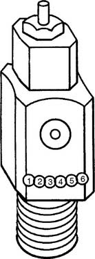
Figure 6-1 Locations of the Pin Index Safety System holes in the cylinder valve face.
(Modified from Branson RD, Hess DR, Chatburn RL: Respiratory care equipment, ed 2, Philadelphia, 1999, Lippincott Williams & Wilkins.)
TABLE 6-3 Pin Index Safety System Gases and Pinhole Locations
| Gas | Pinhole Locations |
|---|---|
| Oxygen | 2-5 |
| Air | 1-5 |
| Oxygen/carbon dioxide (≤7%) | 2-6 |
| Oxygen/carbon dioxide (>7%) | 1-6 |
| Oxygen/helium (not >80% helium) | 2-4 |
| Oxygen/helium (helium >80%) | 4-6 |
| Nitrous oxide | 3-5 |
| Ethylene | 1-3 |
| Cyclopropane | 3-6 |
It is necessary to “crack” or blow some gas out of a cylinder before putting any reducing valve or regulator onto the cylinder. Do this by attaching the tank wrench to the valve stem and slowly turning the valve stem in a counterclockwise (so-called “lefty-loosy”) direction to release some gas. This cracking is done to prevent any dust or debris from being forced into the reducing valve or regulator, which might cause a fire. See Figure 6-2 for a schematic drawing of an “E” tank of oxygen and how its yoke is connected. If the O-ring is missing or the yoke is misaligned on the post, a high-pressure gas leak will occur when the tank is opened with the tank wrench. Close off the tank to stop the leak by turning the tank wrench on the valve stem in a clockwise direction (so-called “righty-tighty”). Investigate the yoke-to-post connection to identify causes of the leak.
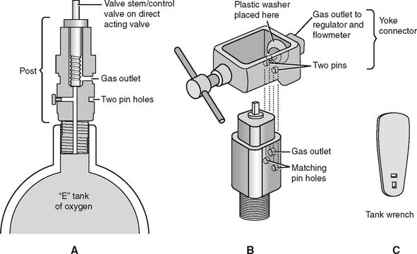
Figure 6-2 Details of an “E” size tank of oxygen and its yoke connector. A, A cross section through the stem (also called the control valve) of the tank shows its key features. B, A three-dimensional view shows how the yoke with its two pins aligns with the corresponding pin holes (locations 2 and 5) on the yoke. The plastic washer ensures a seal between the gas outlet on the stem and the yoke. (Not shown is the regulator that attaches to the yoke. See Figure 6-9.) C, A tank wrench that is attached to the valve stem (also called a control valve). Turn the wrench in a counterclockwise direction to open the tank and allow gas flow; close the tank to stop gas flow by turning the wrench in a clockwise direction.
(Redrawn from Sills JR: Respiratory care for the health care provider, Albany, 1998, Delmar Publishers.)
2. Flowmeters
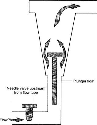
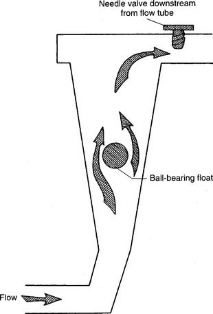
Figure 6-3 Kinetic-type non–backpressure-compensated (pressure-uncompensated) flowmeter.
(Modified from McPherson SP: Respiratory care equipment, ed 4, St Louis, 1990, Mosby.)
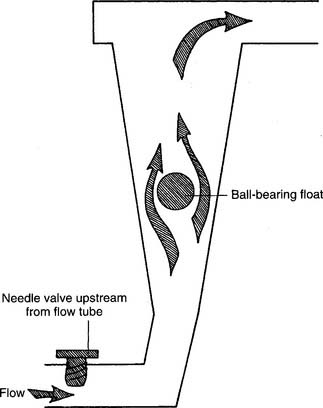
Figure 6-4 Thorpe-type non–backpressure-compensated (pressure-uncompensated) flowmeter.
(Modified from McPherson SP: Respiratory care equipment, ed 4, St Louis, 1990, Mosby.)
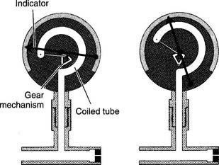
Figure 6-5 Bourdon-type non–backpressure-compensated (pressure-uncompensated) flowmeter.
(From McPherson SP: Respiratory care equipment, ed 4, St Louis, 1990, Mosby.)
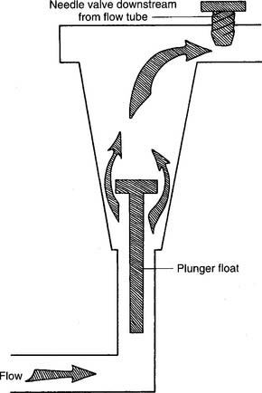
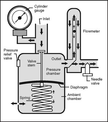
Figure 6-6 Kinetic-type backpressure-compensated (pressure-compensated) flowmeter.
(Modified from McPherson SP: Respiratory care equipment, ed 4, St Louis, 1990, Mosby.)
d. Perform quality control procedures for flowmeters (Code: IIC6) [Difficulty: ELE: R, Ap; WRE: An]
1. Regulators
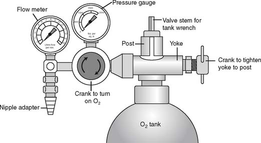
Regulators combine a reducing valve and a flowmeter (Figure 6-8). Everything that has been discussed so far relates to regulators. Bourdon gauge reducing valves usually are seen and can have a second Bourdon gauge added as a flowmeter (Figure 6-9) or a Thorpe or kinetic flowmeter. As mentioned earlier, use a backpressure-compensated flowmeter in all situations except for patient transport.
3. Manipulate pulse-dose oxygen-conserving devices by order or protocol (ELE code: IIA9b) [Difficulty: R, Ap, An]
a. Get the necessary equipment for the procedure
b. Put the equipment together and make sure that it works properly
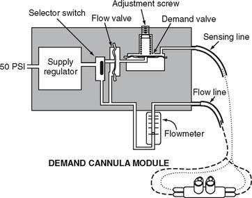
With a pulse-dose system, the proximal end of a special nasal cannula is attached to a pressure sensor on the pulse-dose system. It senses a decrease in pressure as the patient inspires. The sensor then opens a demand valve that delivers a burst of oxygen to the cannula. See Figure 6-10. Because the nasal cannula is directly attached to the pressure sensor, a bubble-type humidifier cannot be added into the system.
c. Troubleshoot any problems with the equipment
If the patient cannot feel any oxygen flowing, the following should be considered: (1) the source of oxygen might be empty, (2) the tubing might be disconnected or kinked, or (3) the sensor may not be detecting the patient’s effort. The patient or therapist can switch to a second oxygen source and look for disconnections or kinks in the tubing. The therapist must adjust the nasal cannula or sensor to correct for a sensitivity problem. Do not use a system that is malfunctioning and cannot be adjusted.
4. Manipulate air compressors by order or protocol (Code: IIA9f) [Difficulty: ELE: R, Ap; WRE: An]
c. Troubleshoot any problems with the equipment
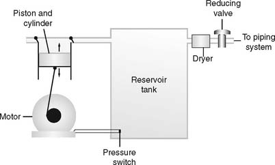
Air compressors are used whenever a high-pressure gas source other than oxygen is needed. All three systems are alike in that they use an electrically powered motor, filter the room air as it enters and exits the compressor, and have a condenser to remove water vapor as it leaves the compressor. See Figure 6-11.
1. Rotary-type compressors
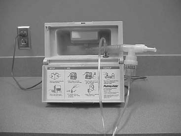
Rotary-type compressors generate pressure with a rotating fan. They are used commonly in volume ventilators and in the home to power hand-held medication nebulizers. (See Figure 6-12.)
5. Manipulate air/oxygen proportioners (blenders) by order or protocol (ELE code: IIA9a) [Difficulty: ELE: R, Ap, An]
a. Get the necessary equipment for the procedure
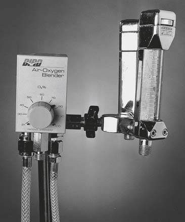
Oxygen blenders are designed to change the ratio of oxygen and air to blend the specific percentage of oxygen from 21% to 100% (Figure 6-13). They are used whenever high-pressure gas is needed and the oxygen percentage may need frequent adjustment.
6. Manipulate oxygen concentrators (Code: IIA9c) [Difficulty: ELE: R, Ap; WRE: An] and portable oxygen concentrators (WRE code: IIA9e) [Difficulty: WRE: R, Ap, An] by order or protocol
a. Get the necessary equipment for the procedure
1. Molecular sieve
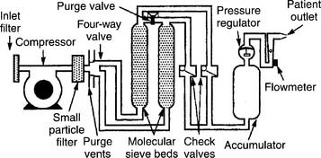
Molecular sieve–type oxygen concentrators use an air compressor to push room air through two canisters of zeolite pellets (inorganic sodium-aluminum silicate) to remove nitrogen and water vapor. The remaining oxygen is delivered to the patient through a flowmeter (Figure 6-14). Be aware that with this unit, the oxygen percentage varies inversely with the flow that is delivered (Table 6-4).
TABLE 6-4 Comparison of Flow Rates and Oxygen Percentages in Oxygen Concentrators
| Flow, L/min | Approximate Oxygen Percentage |
|---|---|
| MOLECULAR SIEVE CONCENTRATOR | |
| 1-2 | 95%-92% |
| 3-5 | 92%-85% |
| >6 | <85% |
| SEMIPERMEABLE MEMBRANE CONCENTRATOR | |
| 1-10 | 40% |
2. Semipermeable plastic membrane
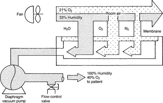
Semipermeable plastic membrane oxygen concentrators make use of a very thin plastic membrane as a filter. Room air is pulled through it by a vacuum pump. Molecular oxygen and water vapor can pass through the membrane faster than nitrogen. Any excess water vapor is removed by a simple condenser system. No need exists to add an external humidification system to the flowmeter (Figure 6-15). The oxygen percentage is fixed at 40% in these units; however, the flow can be varied from 1 to 10 L/min, as shown in Table 6-4.
When one is deciding which type of concentrator to use, it is important to know the patient’s required oxygen percentage and flow. As can be seen from Table 6-4, the molecular sieve units can deliver a higher oxygen percentage at any liter flow as compared with the semipermeable plastic membrane units.


