15 Mechanical Ventilation of the Adult
Note 1: This book is written to cover every item listed as testable on the Entry Level Examination (ELE), Written Registry Examination (WRE), and Clinical Simulation Examination (CSE).
The listed code for each item is taken from the National Board for Respiratory Care (NBRC) Summary Content Outline for CRT (Certified Respiratory Therapist) and Written RRT (Registered Respiratory Therapist) Examinations (http://evolve.elsevier.com/Sills/resptherapist/). For example, if an item is testable on both the ELE and the WRE, it will be shown simply as: (Code: …). If an item is testable only on the ELE, it will be shown as: (ELE code: …). If an item is testable only on the WRE, it will be shown as: (WRE code: …).
MODULE A
1. Ventilator flow, volume, and pressure waveforms
a. Review the patient’s chart for information on airway graphics (Code: IA7c) [Difficulty: ELE: R; WRE: Ap]
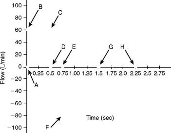
A patient who has been intubated and placed on a modern mechanical ventilator with a microprocessor and graphics software can have ventilator flow, volume, and pressure waveforms visualized on the monitor, stored in memory, or printed out. Look for this information and compare it with the patient’s current situation. See Figure 15-1 for examples of pressure, volume, and flow tracings. See Figure 15-2 for key points of information available from a flow vs. time graph.
b. Perform the procedure to measure ventilator pressure/volume and flow/volume loops (WRE Code: IB9o) [Difficulty: WRE: R, Ap, An]
c. Select ventilator graphics (Code: IIID3) [Difficulty: ELE: R, Ap; WRE: An]
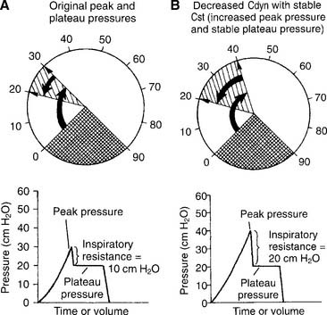
The operator typically can select any two of the following for display on the monitor: time, flow, pressure, and/or volume. Certain combinations are selected to best present the needed information. For example, air trapping is best shown by comparing flow vs. time (Figure 15-3) peak and plateau pressures are best shown by comparing pressure vs. time (Figure 15-4), and lung inflection points are best shown by comparing volume vs. pressure (discussed later). Note examples of ventilator graphics throughout this chapter.
d. Interpret ventilator pressure/volume and flow/volume loops (WRE code: IB10o) [Difficulty: WRE: R, Ap, An]
A number of flow, volume, and pressure waveforms have been included in this chapter for practice. In addition, review Figures 4-1 and 4-10 for examples of pulmonary function test waveform tracings. The examples in this chapter include common clinical situations and are accompanied explanations to help with interpretation.
2. Review the patient’s chart for information on the work of breathing (Code: IA7d) [Difficulty: ELE: R; WRE: Ap]
A patient who has been intubated and placed on a modern mechanical ventilator with a microprocessor and graphics software can have WOB measured. See Figure 15-5 for a pressure/volume loop tracing that shows a patient’s WOB. WOB is minimized when the ventilator is set to minimize the negative pressure and inspiratory flow the patient has to generate.
3. Airway resistance
a. Review the patient’s chart for information on airway resistance (Code: IA7d) [Difficulty: ELE: R; WRE: Ap]
Airway resistance (Raw) may have been measured earlier in the pulmonary function laboratory or on the ventilator. Compare any earlier values with new measurements. This is important for understanding the patient’s trends toward an improving or worsening pulmonary condition.
b. Recommend measurement of the patient’s airway resistance (Code: IC7) [Difficulty: ELE: R, Ap; WRE: An]
c. Determine the patient’s airway resistance (Code: IB9n) [Difficulty: ELE: R, Ap; WRE: An]
1. Procedure for calculating airway resistance
4. Auto-PEEP detection
a. Perform the procedure to detect auto-PEEP (WRE code: IB9w) [Difficulty: WRE: R, Ap, An]
Auto-PEEP is positive end-expiratory pressure in the lungs that cannot be seen on the ventilator’s pressure manometer. (The terms inadvertent PEEP and intrinsic PEEP also are used.) Auto-PEEP is caused by air trapping resulting from an inadequate expiratory time. It becomes more likely when the inspiratory time is increased or the expiratory time is decreased, or in patients with long time constants of ventilation. Simply put, the next breath is delivered before the patient has exhaled completely (see Figure 15-3). This problem is seen frequently in patients with status asthmaticus or COPD because of early small airway closure. In patients with acute respiratory distress syndrome (ARDS) who are receiving pressure-controlled inverse ratio ventilation (PCIRV), the long inspiratory times used increase the risk of expiratory air trapping. Auto-PEEP is more likely to be found when the inspiratory/expiratory (I : E) ratio becomes 2 : 1 or greater.
It is important to add any auto-PEEP to the amount of therapeutic PEEP the patient has. This should be recorded as the total PEEP. For example, the patient has 5 cm of therapeutic PEEP and 2 cm of auto-PEEP for 7 cm of total PEEP. It may be thought that the total PEEP level places the patient at risk for volutrauma or decreased venous return and lowered cardiac output. The amount of auto-PEEP can be reduced by decreasing the inspiratory time, increasing the expiratory time, or decreasing the tidal volume. Lack of auto-PEEP can be confirmed by this procedure. If the auto-PEEP cannot be eliminated, therapeutic PEEP can be added to match it. By increasing the baseline pressure, the patient can more easily trigger an assisted or synchronous intermittent mandatory ventilation (SIMV) breath. It is especially important to decrease auto-PEEP and therapeutic PEEP levels as the patient’s lung compliance improves and airway resistance returns to normal.
b. Interpret ventilator graphics to detect auto-PEEP (WRE code: IB10w) [Difficulty: WRE: R, Ap, An]
Figure 15-3 demonstrates two ways that air trapping on exhalation can be identified as auto-PEEP (unintended positive end-expiratory pressure). Note in Figure 15-3 (bottom) that the patient’s expiratory flow does not reach baseline pressure before another breath is delivered. This proves that air trapping has occurred. The larger the gap between the pressure at the end of expiration and at baseline, the greater is the air trapping.
5. Determine the patient’s plateau pressure (Code: IB9n) [Difficulty: ELE: R, Ap; WRE: An]
The hold should be held for about 2 seconds so that the pressure manometer value is stable. Note the pressure as the plateau pressure (see Figure 15-4, A). After the plateau pressure has been determined, the patient must exhale completely. It may be necessary to delay the next timed ventilator tidal volume breath to avoid “stacking” a new breath when the first has not yet been exhaled. It is recommended that the plateau pressure procedure be repeated to ensure that the measured pressure is accurate.
6. Lung compliance
a. Review the patient’s chart for information on lung compliance (Code: IA7d) [Difficulty: ELE: R; WRE: Ap]
b. Recommend measurement of the patient’s lung compliance (Code: IC7) [Difficulty: ELE: R, Ap; WRE: An]
c. Determine the patient’s plateau pressure and lung compliance (Code: IB9n) [Difficulty: ELE: R, Ap; WRE: An]
1. Procedure for calculating the tubing compliance factor
For greatest accuracy in the calculation of static and dynamic compliance and the calculation of actual tidal and sigh volumes, any lost volume must be subtracted from the exhaled tidal volume to find the actual tidal volume. The tubing compliance factor is used in the calculation to determine the compressed volume, through the following procedure:
2. Procedure for calculating static compliance
3. Procedure for calculating dynamic compliance
in which compressed volume is Compliance factor × Peak pressure.
7. Interpret the patient’s lung mechanics results: plateau pressure, airway resistance, dynamic lung compliance, and static lung compliance values on the ventilator (Code: IB10n) [Difficulty: ELE: R, Ap; WRE: An]
a. Decreased dynamic compliance with stable static compliance
Decreased dynamic compliance with stable static compliance is noticed as an increase in the peak pressure with an unchanged plateau pressure (see Figure 15-4). It is caused by increased airway resistance (bronchospasm, secretions, water in the circuit, kinked circuit, or endotracheal tube). Correction of the underlying problem results in return of the peak pressure to the original level.
b. Increased dynamic compliance with stable static compliance
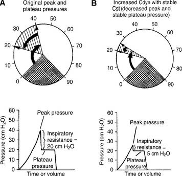
Increased dynamic compliance with stable static compliance is noticed as a decrease in peak pressure with an unchanged plateau pressure (Figure 15-7). This represents an improvement in the patient’s airway resistance from the original condition. Secretions can be diminished, mucus plugs cleared, bronchospasm corrected, and so forth.
c. False decreased dynamic compliance with true decreased static compliance
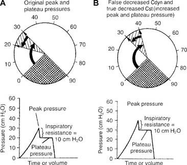
False decreased dynamic compliance with true decreased static compliance is noticed as an increase in both peak and plateau pressures (Figure 15-8). This is seen when the patient’s lung/thoracic compliance worsens. The plateau pressure is elevated, and the static compliance is decreased.
d. True decreased dynamic compliance with true decreased static compliance
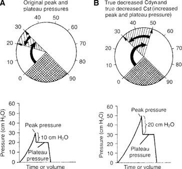
True decreased dynamic compliance with true decreased static compliance also is noticed as an increase in both peak and plateau pressures (Figure 15-9). This is seen with the combination of decreased lung compliance and increased airway resistance. Causes of both of these problems were discussed earlier.
e. False increased dynamic compliance with true increased static compliance
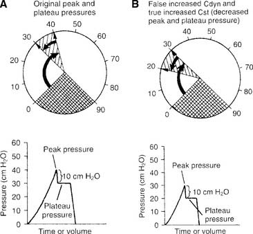
False increased dynamic compliance with true increased static compliance is noticed as a decrease in both peak and plateau pressures (Figure 15-10). This is seen when the patient’s lung/thoracic compliance improves. The plateau pressure decreases, and, as an artifact, the peak pressure also decreases. Notice that the difference between peak and plateau pressures remains the same. This indicates that the patient’s airway resistance is unchanged.
f. True increased dynamic compliance with true increased static compliance
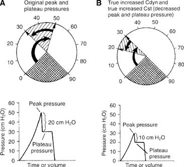
True increased dynamic compliance with true increased static compliance also is noticed as a decrease in both peak and plateau pressures (Figure 15-11). This is seen when the patient’s airway resistance and his or her lung/thoracic compliance improve. Notice that the plateau pressure has decreased, thus indicating more compliant lungs. Also notice that the difference between peak and plateau pressures has decreased. This demonstrates that the airway resistance also has decreased.
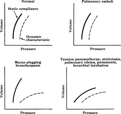
All six examples of increasing or decreasing static or dynamic lung compliance or both make use of a single tidal volume that is analyzed for peak and plateau pressures. Some practitioners advocate using several different tidal volumes (e.g., 8, 10, and 12 mL/kg of ideal body weight) when measuring dynamic and static pressures. The measured values are plotted on a graph to find the patient’s optimal tidal volume that results in the highest static compliance value. Figure 15-12 shows a series of these graphs. The curves for diseased lungs and airways are quite different from those of a normal person or a patient with a pulmonary embolism. Because of this, a pulmonary embolism should be considered if the patient’s condition deteriorates rapidly and no change in dynamic or static compliance values is observed.
MODULE B
Conventional mechanical ventilation is defined here as the use of a single ventilator that can provide the customary modes and options needed by the large majority of patients. This ventilatory support is provided through an endotracheal tube or a tracheostomy tube. Several physiologic criteria have been compiled to help the clinician determine when a patient is in respiratory or ventilatory failure (Box 15-1) and needs ventilatory support. Remember that the patient may not fail each and every criterion; however, the patient often will fail one or more criteria in each category.
BOX 15-1 Indications for Ventilatory Support
VENTILATION
PaCO2 ≥55 torr in a patient who is not ordinarily hypercapneic
Dead space: tidal volume (VD/VT ratio) of >0.55–0.6 (55%-60%)
PULMONARY MECHANICS
Spontaneous tidal volume 3-4 mL/lb or 7-9 mL/kg of ideal body weight
Maximum inspiratory pressure (MIP) <-20 to −25 cm water pressure
Forced expiratory volume in 1 second (FEV1) <10 mL/kg
Respiratory rate <12 breaths/min or >35 breaths/min in an adult
Rapid, shallow breathing index (breaths/minute divided by tidal volume in liters) >105
1. Perform the following procedures to make sure that the patient is adequately oxygenated
a. Minimize hypoxemia by positioning the patient properly (WRE code: IIID7) [Difficulty: Ap, An]
b. Administer oxygen, as needed, to prevent hypoxemia (ELE code: IIID6) [Difficulty: ELE: R, Ap, An]
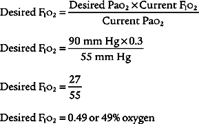
Oxygen administration and adjustment were discussed in Chapter 6. In brief, the goal of oxygen administration is to keep the Pao2 level of most patients between 60 and 90 torr and the Spo2 level greater than 90%. Exceptions are the patient with COPD who is breathing on hypoxic drive and the patient who is in a cardiac arrest situation. The following formula can be used to help guide the use of supplemental oxygen in most stable patients:
in which F1 is the flow of first gas (oxygen), C1 is the concentration of oxygen in the first gas (1.0 for pure oxygen), F2 is the flow of second gas (air), C2 is the concentration of oxygen in the second gas (0.21 for air), FT is the total flow of both gases, and CT is the concentration of oxygen in the mix of both gases. Use algebraic manipulation to solve for the unknown.
c. Adequately oxygenate the patient to prevent accidental hypoxemia before and after suctioning, changing the ventilator circuit, or performing other procedures in which the patient is disconnected from the ventilator (ELE code: IIID9) [Difficulty: ELE: R, Ap, An]
Ensuring adequate oxygenation during suctioning is discussed in Chapter 13. In brief, remember to give the adult patient 100% oxygen for at least 30 seconds before suctioning. Perform the task as quickly and safely as possible to minimize time off the ventilator. Leave the patient on 100% oxygen for at least 1 minute after the procedure is completed, or until he or she returns to a stable condition as before the procedure. Children younger than 6 months can have the FIo2 increased by 10% for the procedure.
2. Initiate and adjust continuous mechanical ventilation settings (Code: IIID2b) [Difficulty: ELE: R, Ap; WRE: An]
b. Flow
Flow is adjusted to set the inspiratory time and the I : E ratio. In addition, flow is set to meet the patient’s needs. Inspiratory flow should be great enough to minimize the WOB. Increase flow if the patient has signs of greater demand, such as using accessory muscles of inspiration or lack of synchrony with the ventilator, or if the pressure manometer deflects greatly below the baseline pressure or shows a low initial increase in inspiratory pressure.
In addition, most current generation ventilators offer more than one inspiratory flow pattern (see Figure 15-1). The sine wave is most physiologically like a normal, spontaneous inspiration. The other waveforms can be compared with the sine wave to determine which one best meets the patient’s needs. Ideally, the best flow pattern is one in which the patient’s peak and mean airway pressures are lowest, exhalation is complete, breath sounds are improved bilaterally, heart rate and blood pressure are stable, and the patient feels most comfortable.
c. I : E ratio
The I : E ratio is adjusted to ensure that the patient can inhale in as physiologically appropriate a manner as possible and completely exhale the inspired tidal volume. Typically, the I : E ratio should be 1 : 2 or more. Incomplete exhalation will cause air trapping and auto-PEEP (see Figure 15-3).
f. Modes of ventilation
1. Control
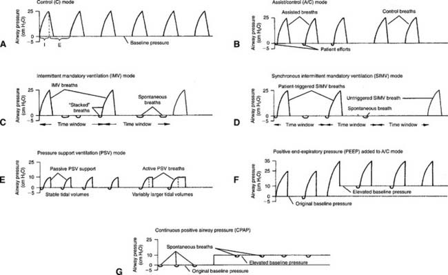
Control (C) is the simplest method of providing ventilatory support and is used on an apneic patient. The ventilator is set with a mandatory respiratory rate and tidal volume. The machine is incapable of allowing any patient interaction. For example, the ventilator might be set to deliver a tidal volume of 700 mL at a rate of 14 times/min. Because of this limitation, it is rarely, if ever, used in modern medicine except when the patient must be kept sedated or pharmacologically paralyzed (Figure 15-13 shows the pressure/time curve).
2. Assist/control
The assist/control (A/C) mode has a set backup respiratory rate but allows the patient to trigger additional machine-delivered breaths. A sensitivity control is adjusted to allow the patient to start a breath easily as needed. All tidal volumes are the same (Figure 15-13, B shows the pressure/time curve).
3. Intermittent mandatory ventilation
IMV was used in older ventilators before there was a way to synchronize the patient and ventilator breaths. With IMV, a set backup respiratory rate and tidal volume are delivered to the patient. In addition, between mandatory breaths, the patient can breathe spontaneously as frequently as desired. The patient also can take in as large a spontaneous tidal volume as needed. The sensitivity control is set so that the patient cannot trigger any extra ventilator tidal volume breaths (Figure 15-13, C shows the pressure/time curve). The IMV mode has been replaced in modern ventilators with the SIMV mode, as discussed below.


