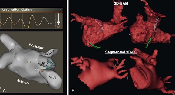
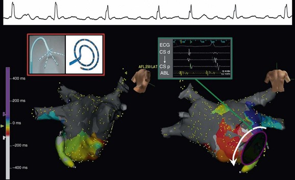
60 Entrainment mapping is an extremely useful technique to provide evidence that the mechanism of a particular arrhythmia is reentry with an excitable gap, as opposed to an automatic mechanism or triggered activity.1 In addition, once the mechanism of a rhythm is known to be reentry, entrainment maneuvers can be performed to dissect the pathway of the arrhythmia—be it of atrial or ventricular origin.2 By observing the response of the return cycle at cessation of entrainment (also referred to as continuous resetting), it is possible to determine whether the site of pacing is an active part of the circuit or is an irrelevant or passive location. That is, if within the circuit, the return cycle at the cessation of pacing would be equivalent to the tachycardia cycle length; if outside the circuit, the return cycle would be longer than the tachycardia cycle length. Furthermore, the morphology of the paced ECG complex (again, more useful for ventricular rhythms) can be compared to the arrhythmia’s ECG complex to determine whether the area (from which entrainment is performed) is within a constrained location. This would be relevant because the constrained areas are typically better sites to target for ablation. In addition to activation, pacemapping, and entrainment mapping, there are a few other specialized mapping approaches that can be helpful. During standard catheter mapping of an arrhythmia, the pressure from the catheter can cause transient tissue dysfunction that, if applied at a critical site, can terminate the tachycardia. This can occur in certain scar-related atypical atrial flutters and scar-related VTs, but the most common systematic use of this approach is during mapping of Mahaim tachycardias.3 The atrionodal or atrioventricular pathways that potentiate these tachycardias are typically located at the endocardial surface and are prone to pressure-induced transient interruption of conduction. Accordingly, one can capitalize on this phenomenon and use an approach of “bump” mapping, during which the catheter is used to apply pressure to various locations along the tricuspid valve such that when conduction is transiently interrupted, ablation is performed to eliminate the putative pathway. One problem with this approach is the unpredictability of the time before conduction resumes. This is particularly problematic if the exact time or location of the bump is not known; therefore, bump-mapping must be performed carefully, ideally with use of an EAM system so that the location can be spatially catalogued in a precise manner. Cryomapping is another approach that can provide transient arrhythmia interruption, but in a more predictably reversible manner.4 A cryocatheter is manipulated to the site thought to be critical to the arrhythmia circuit. Next, refrigerant is delivered to the catheter tip, but only to achieve a tip temperature of −30 °C—a temperature that is not cold enough to ablate any appreciable amount of tissue, but cold enough to cause transient interruption of electrical conduction. Cryomapping is particularly useful when the target arrhythmia is within close spatial proximity to a critical normal structure, such as during catheter ablation of a para-Hisian accessory pathway. The system also enables faster, high-quality anatomic recreation using a nongated mapping mode termed fast anatomic mapping (FAM; Figure 60-1). Although the system requires the use of Biosense Webster electrode catheters, anatomic reconstruction can be facilitated, especially in the left atrium with the use of multielectrode circular mapping catheters. One important caveat regarding FAM is the effect of respiration on the quality of the anatomic rendering that is created. The multiple patches of the CARTO 3 system permit the introduction of an algorithm for respiratory gating. To track respiration, the system uses impedance readings derived from inter-patch measurements, termed respiration indicators. The inter-patch current (from one patch to the other) passes through the lungs, thereby recording changes in impedance owing to pulmonary air volume. For the algorithm to provide good respiratory gating performance, one first performs a “training” step in which the mapping catheter is placed in the heart, touching a chamber wall for recording heart motion during respiration. During training, a correlation matrix is calculated that best correlates the respiratory indicators to catheter motion. Although training is sampled in one location, it remains valid for the entire heart because the training is used only to allow the algorithm to perceive the time point in the respiratory cycle. Figure 60-1 Left atrium and pulmonary veins (LA-PV) anatomical reconstructions by electroanatomical mapping systems: A, Shown at top is an example of the respiratory changes during mapping. Gating is applied such that spatial information is acquired only near end-expiration, as depicted by orange. At bottom is a superior view of a three-dimensional (3D) fast anatomic mapping reconstruction of the LA-PV anatomy using CARTO. B, The 3D LA-PV geometries constructed by NavX (top) are CT-like quality. A training graph is generated to allow the operator to select the detection threshold (see Figure 60-1). Using a lower respiratory threshold permits more gating and results in more accurate maps; however, this comes at the expense of time. When the respiratory threshold is set low, data accuracy is high; when the threshold is higher, data addition to the map is faster, but map accuracy is compromised. The operator must use discretion based on the patient’s clinical indication; indeed, a low threshold can be set in one region in which spatial accuracy is less critical, and then changed to a higher level for another region in the same chamber. The range of options with this system (e.g., different mapping modes, mapping with either a standard quadripolar mapping catheter or a multielectrode catheter, various respiratory gating strategies) can be somewhat bewildering, but ultimately one must identify a workflow to achieve the desired outcome. For example, when mapping the left atrium and pulmonary veins, it is preferable to perform FAM using a circular mapping catheter (see Figure 60-1). First, respiratory gating training is performed by placing the catheter in the left inferior pulmonary vein (PV). For mapping the PVs, FAM is performed using the lowest respiratory threshold possible, with the FAM reconstruction resolution set at a high level because accuracy of these regions is key to successful ablation. In addition, each PV and left atrium (LA) appendage is acquired in separate maps. After mapping all veins, the respiratory threshold is increased somewhat when acquiring the LA body. Finally, before initiating ablation, the magnetically localized ablation catheter is introduced to regions of importance, such as the LA appendage ridge, to ensure that they were mapped correctly. One important limitation to using a circular mapping catheter is the fact that the PVs can be somewhat stretched by the almost inevitable mismatch between the catheter diameter and PV. Mapping with NavX is typically a two-step process. First, by moving a catheter to trace the endocardial contour of the chamber of interest, a virtual 3D geometry is constructed. Subsequently, sequential point-by-point mapping can be performed to generate color-coded maps of electrical information such as activation, voltage amplitude, and propagation. Over time, the ability of the system to perform these two steps has improved tremendously. By using a multielectrode catheter, it is possible to generate a computed tomography (CT)–like geometric rendering of the left atrium and PVs; in some sense, this can be viewed as electroanatomical imaging (see Figure 60-1). (This is also true for FAM maps created using CARTO.) Furthermore, multielectrode spiral or penta-array mapping catheters can be used to create high-density, accurate electrical maps in only a few minutes. The NavX system has proved itself to be particularly useful for mapping and ablating complex atypical atrial flutters (Figure 60-2).5 This process involves four steps. First, the multielectrode catheter is maneuvered with a deflectable sheath along the chamber to create a high-density map—approximately 500 points in less than 10 minutes. Second, the wavefronts are analyzed to identify potential critical isthmuses as areas of constrained activation (resulting from idiopathic or iatrogenic scars and anatomic barriers), often also containing fractionated electrograms. Third, entrainment pacing maneuvers are performed from the ablation catheter at these sites to determine which of these wavefronts are actually “active” parts of the circuit versus “passive” bystanders. Finally, the area of slow conduction that is active in the circuit and preferably in a constrained region is targeted for catheter ablation. Figure 60-2 Fast multielectrode mapping of atypical atrial flutter. This patient with a medical history of both catheter and surgical AF ablation had incessant atypical atrial flutter. A multielectrode catheter (such as the penta-array or spiral catheter) was maneuvered around the LA-PV chamber to acquire a dense activation map by NavX in approximately 5 minutes. An area of constrained activation between atrial scar and the anterosuperior mitral valve annulus was identified; at this location, the electrogram was fractionated, and the postpacing interval after entrainment was equal to the flutter cycle length. A single lesion at this location permanently eliminated the flutter. Because all catheters can be visualized nonfluoroscopically by the NavX system, there is the possibility for truly fluoroless mapping and ablation of cardiac arrhythmias, thereby reducing or eliminating exposure to ionizing radiation to patients and staff members. Using the NavX system, it is possible to introduce and map the cardiac chambers to perform catheter ablation of not just simple arrhythmias such as right-sided supraventricular tachycardias (SVTs), but even complex arrhythmias such as atrial fibrillation.6–8 To accomplish this goal, first the diagnostic catheters are visualized using the NavX system from the point of entry into the femoral vessels to the heart. Second, the transseptal puncture procedure is performed using intracardiac ultrasound (discussed later) to visualize the guidewire being placed into the superior vena cava (SVC), advancement of the transseptal sheath over the guidewire, movement of the transseptal sheath and needle assembly down to the interatrial septum, and puncture of the septum into the left atrium. Third, a multielectrode catheter is maneuvered to create a 3D cast of the left atrium and pulmonary veins (LA-PVs). Finally, the ablation catheter is manipulated to perform the ablation procedure. Although the clinical utility of completely fluoroless catheter mapping and ablation in most adult patients is debatable, it is clear that certain populations derive unique benefits from this approach: children (who can absorb tremendous amounts of radiation) and pregnant women whose arrhythmias cannot otherwise be managed. Most importantly, the fact that truly fluoroless atrial fibrillation (AF) ablation is possible clearly indicates that with conscious effort, x-ray exposure can be minimized to a much greater extent than is typical in most electrophysiology laboratories. The Rhythmia system uses a steerable small basket array catheter of 64 electrodes to obtain a high-resolution electroanatomical activation map, hopefully with minimal need for annotation (Figure 60-3).9 The 64 electrodes are arranged on 8 splines forming a spherical shape when deployed. Mapping is performed by roving this fully- or partially-deployed catheter within the chamber while displaying electrogram and EAM information. For electrical mapping, a suite of algorithms monitors the incoming data, aligns it according to a timing reference, and uses a rules-based approach to determine continuously which beat should be acquired into the map and where the electrogram should be annotated. To determine which beats should be acquired, the software considers multiple factors, such as respiration and electrogram morphology. Rules are defined by the operator and can be adjusted separately for each map.
Mapping and Imaging
Mapping
Conventional Mapping Techniques
Entrainment Mapping
Miscellaneous Mapping Approaches
Electroanatomical Mapping Systems
The CARTO System

The NavX System

The Rhythmia System
![]()
Stay updated, free articles. Join our Telegram channel

Full access? Get Clinical Tree


Mapping and Imaging
