Chapter 23
Magnetic Resonance Imaging
Harold Litt, Jeffrey P. Carpenter
Magnetic resonance imaging (MRI) is performed by using a large external magnetic field, magnetic field gradients, and an applied oscillating magnetic field known as the radiofrequency field (RF). The combination of these three types of applied magnetic fields allows the user to produce signals from inside patients, which in turn can be used to create MR images.
Basic Principles
The details of the external magnetic field, magnetic field gradients, and RF determine many of the characteristics of MR images. The goal of the external magnetic field is to magnetize the subject by making the protons within the subject align parallel with the external field. The physical characteristics of the protons and the size of the external magnetic field define the resonance frequency of the proton. If the external magnetic field is uniform, all the protons will resonate at the same frequency. Most MRI machines operate at an external field strength of 1.5 or 3 tesla (T); the potential advantages of 3-T magnetic resonance angiography (MRA) are discussed later in the chapter. Lower field systems, those less than 1.0 T, tend to produce images at a slower rate or at a lower resolution than is typically desirable for MRA examinations.
Magnetic field gradients are used to alter the otherwise uniform external magnetic field in a linear fashion in any of three directions. The gradients ramping on and off produce the noise heard when an MR image is being made. When the gradient fields are applied, the protons resonate at a frequency that is a function of the magnetic field gradient’s position. This is analogous to a radio station’s frequency corresponding to a specific position on the dial. The speed and strength of the gradients determine the size of the images and may be a rate-limiting step in imaging speed.
Resonant coils placed adjacent to the region of interest produce the RF. These fields are tuned to match the resonant frequency of the protons inside the patient. The applied RF in combination with the gradients is used to manipulate the protons inside the patient to produce a signal. This signal is detected with a receiver RF coil, also tuned to the resonant frequency of the protons. Once it is detected, the signal is sent to an amplifier and receiver, where it is digitized and processed with a mathematical algorithm known as a Fourier transform to produce the MR image.
Characteristics of MR Images
The contrast in MR images depends on the characteristics of the object being imaged and on the specifics of the sequence itself. Images are typically referred to as either T1 weighted or T2 weighted. T2-weighted images display simple fluids, such as urine, bile, and cerebrospinal fluid, as bright and other tissues as lower signal. T2-weighted imaging is one of the basic sequences for imaging of tumors but is not used for angiographic imaging. MRA and magnetic resonance venography (MRV) are performed with T1-weighted image sequences. Objects that are bright on T1-weighted images, including fat, methemoglobin, flow effects, and MRI contrast agents, will often be seen on MRA as well.
MR Pulse Sequences and Parameters
The MR pulse sequence is a label that refers to the particular combination of RF and gradients that are used to create the image. There are a large variety of MR pulse sequences, but almost all are variations of spin-echo or gradient-echo sequences. Spin-echo pulse sequence methods use RF alone to produce the MR signal, whereas gradient-echo pulse sequences use RF and applied gradients to produce the signal. As a rough generalization, spin-echo pulse sequences are used to produce T2-weighted images and gradient-echo sequences are used to create T1-weighted images.
The characteristics of a tissue that determine its appearance on MR images are the T1 and T2 parameters of the tissue. Some tissues are bright on T1-weighted images, and others are bright on T2-weighted images. How then do we create a T1- or T2-weighted image? All pulse sequences have fundamental parameters known as echo time (TE) and repetition time (TR) that determine image contrast. T2-weighted images have a longer TE, in the range of 80 milliseconds or more, and a longer TR, in the range of several seconds. Because of the long TE and TR, these sequences are slower and not appropriate for contrast-enhanced MRA. T1-weighted images, however, have a very short TR and TE, with a TE of 1 millisecond or less and a TR ranging from hundreds of milliseconds to less than 10 milliseconds for MRA sequences. These fast T1-weighted gradient-echo sequences are used for most angiographic examinations.
Other parameters used in all MR image sequences include the field of view (FOV) and image matrix. FOV is the size of the imaged region. In a two-dimensional (2D) image, FOV may be 40 × 30 cm with a slice thickness of 5 mm. The resolution of the image in that 5-mm slice will depend on the number of pixels within the 30 × 40-cm region. Most MRA, however, is performed with a three-dimensional (3D) image sequence. In this case, FOV is specified with three dimensions, such as 40 × 30 × 30 cm. If we have an image matrix of 256 × 192 × 64, we have a voxel (or 3D pixel) size of 1.56 × 3.26 × 4.7 mm. Image postprocessing is usually performed on 3D data to make the last dimension twice as small as specified by the pulse sequence. In this case, such processing would yield a voxel size of 1.56 × 3.26 × 2.35 mm.
MR Angiography and Venography
Non–Contrast-Enhanced MR Angiography
Non–contrast-enhanced MRA methods, most notably time-of-flight (TOF) imaging, have largely been supplanted by superior contrast-enhanced methods.1–5 However, the recent description of nephrogenic systemic fibrosis (NSF) in patients with poor renal function who have received gadolinium–diethylenetriamine pentaacetic acid (Gd-DTPA)6,7 (see Contrast-Enhanced MR Angiography for further details) has led to renewed interest in non–contrast-enhanced techniques.
TOF angiography uses a rapid T1-weighted pulse sequence in either sequentially acquired 2D slices or a 3D imaging slab. In a single-slice image when data are gathered rapidly, the protons within the slice lose much of their magnetization. Thus, there is much less signal from these protons, and the corresponding tissues are not well seen. The rapid imaging does not degrade any protons outside the slice, however. When fully magnetized protons in a vessel flow into the slice of interest, they produce much greater signal than the surrounding tissue. This results in an image in which the blood flowing into the slice is much brighter than surrounding tissue.
For example, if the image were obtained in an axial slice through the midabdomen, the aorta and inferior vena cava (IVC) as well as some of the mesenteric arteries and veins would be bright. To remove either the arteries or veins, a special RF pulse is applied to the tissue either above or below the slice to eliminate magnetization from that tissue. If an inferior saturation pulse were used in our example, only the protons flowing into the slab from above (the aorta and mesenteric arteries) would be bright. A series of such images obtained sequentially would produce a 2D TOF abdominal angiogram.
Newer techniques for non–contrast-enhanced MRA include steady-state free precession (SSFP),8 arterial spin labeling,9 and half-Fourier fast spin-echo imaging with flow-spoiled gradients.10 These techniques use combinations of several different methods that accentuate the signal of flowing blood and attenuate the signal from nonmoving structures and tissue with signal characteristics different from blood’s. The SSFP technique, for example, provides rapid imaging of both large and small vessels, such as the aorta,11,12 carotids,13 and renal arteries,14 without the need for administration of a contrast agent. In SSFP imaging, the signal of a particular tissue is related to the T2/T1 ratio for that tissue, and flowing blood appears bright. Figure 23-1 shows a non–contrast-enhanced SSFP MR angiogram of the thoracic aorta. By applying additional pulses to null the signal from other tissue with bright signal, such as fat and simple fluid, images of the vessels can be obtained with high contrast. Figure 23-2 shows a non–contrast-enhanced MRA study of the renal arteries, comparing TOF MRA with images obtained with a technique that uses electrocardiographic gating and subtracts diastolic from systolic images, leaving signal only in arteries. Evaluation of these techniques is ongoing15; however, they have the potential to replace contrast-enhanced MRA in many circumstances.
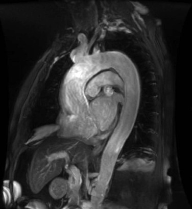
Figure 23-1 Oblique sagittal non–contrast-enhanced steady-state free precession MR angiogram of the thoracic aorta. The signal from flowing blood appears bright.
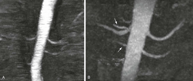
Figure 23-2 A, Coronal maximum intensity projection of time-of-flight MRA of the renal arteries. B, Coronal maximum intensity projection of non–contrast-enhanced MRA acquired with a newer method that uses electrocardiographic gating to subtract diastolic from systolic images, leaving only arterial systolic flow. Note markedly improved visualization of accessory right renal arteries compared with time-of-flight technique (arrows).
Contrast-Enhanced MR Angiography
Currently, MR contrast agents approved by the Food and Drug Administration (FDA) include several in which the rare earth element gadolinium is chelated with another substance to avoid release of toxic free gadolinium into the body. These agents are designed to shorten the T1 of the protons in the vicinity, thereby making them more conspicuous on T1-weighted imaging sequences.
There are several important differences between MR contrast agents and the iodinated contrast material used for computed tomographic angiography (CTA) or catheter angiography. First, as suggested, MRI is designed not to image the agent itself but to image its effect on protons in the surrounding water. This has a subtle implication that is important in certain circumstances. That is, a very small amount of MR contrast material may be detected by its effect on multiple water molecules, whereas an equivalently small amount of iodinated contrast material is simply not detectable directly by CTA or catheter angiography. This is one reason that the volume of MR contrast agents can be much less than the volume of iodinated contrast agents used for CTA or diagnostic angiography. Other advantages of gadolinium-based contrast agents include decreased nephrotoxicity and a lower incidence of reactions to the contrast agent.16–20
Step-Table MR Angiography
For applications involving imaging of a large volume, such as the entire aorta or a peripheral runoff study, acquisition of data from the entire volume of interest is impractical and may lead to decreased image quality. The spatial resolution of the acquired images is inversely proportional to the image matrix size, and the image matrix size has a direct impact on the duration of the acquisition, so a higher resolution image requires a longer time to acquire. If the FOV is very large, a long acquisition time may be required to achieve the necessary spatial resolution for visualization of the vessels of interest, which may be beyond breath-holding capacity of the patient and lead to respiratory motion artifact. In addition, intravenously administered contrast material will flow from the aortic root to distal vessels in a time dependent on the rate and volume of injection, the patient’s cardiac output, and the presence of any proximal occlusive disease; thus, not all portions of the arterial system will be enhancing optimally at the same time. For these reasons, it is desirable to use a step-table acquisition in which portions of the anatomy of interest are imaged sequentially, with the scanner table moving between stations to place the specific anatomy of interest near the isocenter of the magnet.
A peripheral runoff study may include four step-table stations—abdomen/pelvis, thighs, calves, and feet—each imaged with a coil, FOV, spatial resolution, and orientation optimized to the particular vascular anatomy in that station. For example, whereas the abdominal and pelvic vessels may best be imaged in the coronal plane with a larger FOV and a large array coil, the smaller pedal vessels would optimally be acquired in an oblique plane oriented along the foot, with a small FOV, high spatial resolution, and smaller coils for an improved signal-to-noise ratio. Although step-table examinations are generally performed in a proximal to distal direction, there may be circumstances in which a “reverse step-table” protocol is preferable, for example, when imaging a patient with known abdominal aortic disease in whom there is less suspicion of thoracic aortic disease. In this case, the abdominal aorta could be imaged first, in the coronal plane, followed by the thoracic aorta, imaged in a more advantageous oblique sagittal plane. This would provide higher resolution imaging of both regions of the aorta, in two shorter breath-holds, than is possible with a single large-FOV acquisition with imaging of the area of greatest interest in a pure arterial phase and perhaps some venous filling for the less critical thoracic portion.
Three-Dimensional Image Processing
Contrast-enhanced MRA is performed as a 3D imaging sequence. The 3D imaging sequences are typically faster and of higher resolution than non–contrast-enhanced angiograms and provide the same coverage. A 3D image can be viewed as a stack of 2D images, but the higher resolution of 3D methods allows the use of multiplanar reformatting. Multiplanar reformatting involves manipulation of the data to create images from multiple views that optimize visualization of the anatomy or pathology. Images can be processed with many types of algorithms to display the 3D data to best advantage. Because contrast within is designed to have the highest intensity, an algorithm that displays the maximum intensity of the voxels, known as maximum intensity projection,21 is the most commonly used for reformatting of 3D MR angiograms. Volume rendering has recently become a popular evaluation and display method and has been demonstrated to be equivalent or superior to maximum intensity projection for both MRA and CTA of several vascular territories.22,23
Hardware and Software for MR Angiography
MRA is performed optimally on a 1.5- or 3-T MR system with the fastest and strongest gradients available. This will result in shorter acquisition times with higher spatial resolution and improved SNR. Dedicated coils for specific vascular beds are also useful and include at least a neurovascular coil for head and neck MRA and a peripheral angiography coil covering the pelvis to the ankles or toes for runoff studies. MRA of the thoracic, abdominal, and pelvic vessels is performed with multiple flexible phased array coils that can be placed over the anatomy of interest; multichannel coils and RF receivers allow parallel imaging (described later under Parallel Imaging) for faster acquisitions. Digital and pedal vessels can be imaged either with small local extremity coils or by placing both extremities in a dedicated head coil that is designed for high-resolution and SNR imaging.
An MR-compatible dual-chamber power injector is needed for rapid administration of the contrast agent, followed by a saline chaser (which can decrease the amount of contrast agent used). MR-compatible patient monitoring equipment is also useful, especially when imaging hospitalized patients or when sedation is needed. Additional software may be needed for step-table and parallel imaging as well as for newer non–contrast-enhanced and contrast-enhanced MRA techniques, so it is important when purchasing MR systems to investigate which sequences are included in the base MR system package and which are optional. MR-compatible blood pressure cuffs can be useful for reducing venous contamination in extremity MRA. For example, placing cuffs around both thighs while inflating to half to two-thirds systemic arterial pressure effectively delays venous return and allows improved visualization of calf arteries.24
A postprocessing workstation with multiplanar reconstruction, maximum intensity projection, and volume rendering capability is the minimum necessary for visualization and interpretation of MRA studies. Additional software, such as automated vessel analysis with curved planar reformatting, vessel centerline extraction, automated segmentation, and bone removal, may also be useful for specific applications but is more relevant for CTA than for MRA.
Clinical Applications of MR Angiography
Renovascular Disease
For the evaluation of renovascular disease, 3D gadolinium-enhanced MRA has become a clinical standard.25 The most common such disease is atherosclerotic renal artery stenosis. However, MRA has also demonstrated that it is a powerful technique for evaluating more subtle renal vascular conditions, such as fibromuscular dysplasia, renal artery aneurysms, and accessory renal arteries.1 Detection of accessory arteries is particularly important for assessment of potential living renal donors.26–28
Approximately 25% of the middle-aged white and African American population in the United States has high blood pressure.29 Renal artery stenosis is the most common cause of secondary hypertension, and approximately 1% of people with hypertension will have renal artery stenosis.30 Because renal artery stenosis is so common and potentially curable,31–33 it is critical that appropriate screening tests exist for those at risk; 3D contrast-enhanced MRA has a sensitivity of 94% and a specificity of 93%.1 In addition, it has been shown that when MRA is used to plan a renal artery intervention, both the number of pretreatment angiograms and the total amount of contrast material are reduced.34
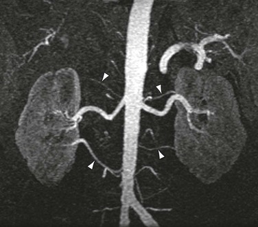
As shown in Figure 23-3, the majority of renal artery stenoses are located in the ostial or proximal35 segments. As methods for 3D contrast-enhanced MRA have improved, diseases that are not typically near the renal artery origin have more commonly been diagnosed by MRA. Such diseases include another curable cause of hypertension, fibromuscular dysplasia,36,37 shown in Figure 23-4.
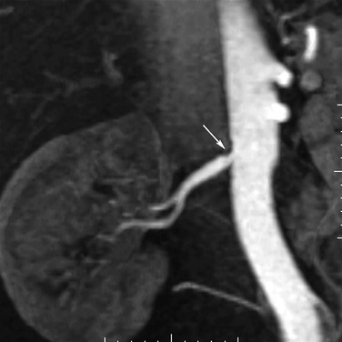
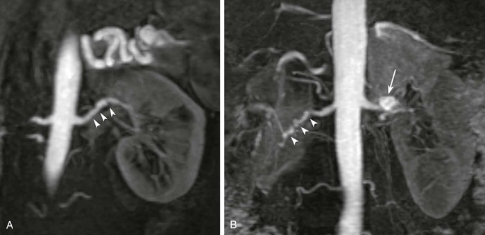
Figure 23-4 A, Coronal 3D MR angiogram showing subtle fibromuscular dysplasia (arrowheads). Note that the disease is isolated to the distal portion of the main renal artery. B, Coronal 3D MR angiogram showing right-sided fibromuscular dysplasia (arrowheads) and a left-sided renal artery aneurysm (arrow). Renal artery aneurysms may occur in patients with fibromuscular dysplasia.
Accessory renal arteries occur in nearly 45% of patients,38 and their diagnosis can be important in screening candidates for renal donation.26,27 MRI and MRA have been shown to be cost-effective methods for evaluating potential renal donors.39 Figure 23-5 demonstrates an individual with six total renal arteries.
Peripheral Vascular Disease
MRA has become a standard method for evaluation of peripheral vascular disease.40 Peripheral vascular disease is extremely common in the middle-aged and elderly population. Its prevalence is approximately 3% in those older than 55 years but increases to 11% in those older than 65 years and is as high as 20% in individuals older than 70 years.40 MRA has been demonstrated to be effective in the preoperative assessment of patients41–43 with peripheral vascular disease, including imaging of inflow vessels44 and evaluation of stenoses,45 as shown in Figure 23-6. Its sensitivity for detecting hemodynamically significant stenoses is 99.5% with a specificity of 98.8% compared with digital subtraction angiography (DSA).45 In addition, MRA is effective in imaging suitable target vessels, including vessels not seen by catheter angiography.45,46 MRA is also a cost-effective method for evaluation of patients with peripheral vascular disease.47,48
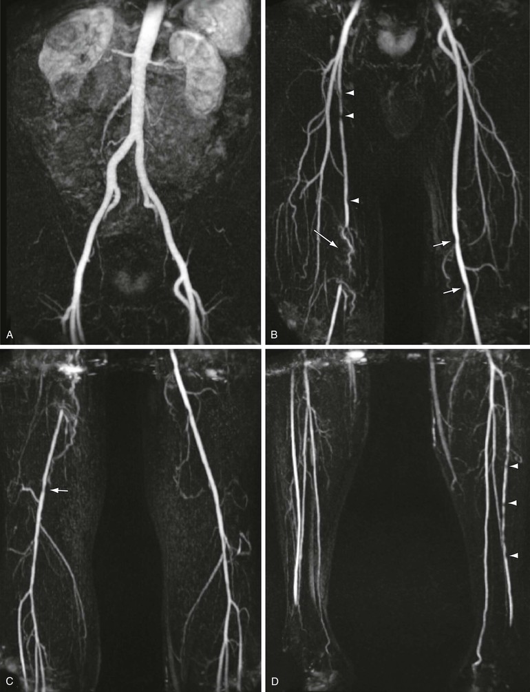
Figure 23-6 Coronal 3D MRA step-table examination showing (A) normal inflow vessels, (B) right proximal superficial femoral artery stenoses (arrowheads), segmental occlusion of the right distal superficial femoral artery/popliteal artery (long arrow), and mild left popliteal stenoses (short arrows), with (C) mild right popliteal artery stenosis (arrow) and (D) multiple stenoses of the left anterior tibial artery (arrowheads).
With the continued advancement in MR technology, MRA evaluation of peripheral vascular disease continues to improve.3,4,49–51 Improvements in step-table examination have increased the speed and resolution of the examination. This has allowed improved visualization of smaller distal vessels and permitted arterial-phase dedicated imaging of the feet, as shown in Figure 23-7. As mentioned previously, MRA has been shown to be superior to DSA for the evaluation of distal vessels in some cases.45,46 In a study of 37 patients, MRA depicted significantly more vascular segments in the foot than DSA did (P ≈ .0001).51
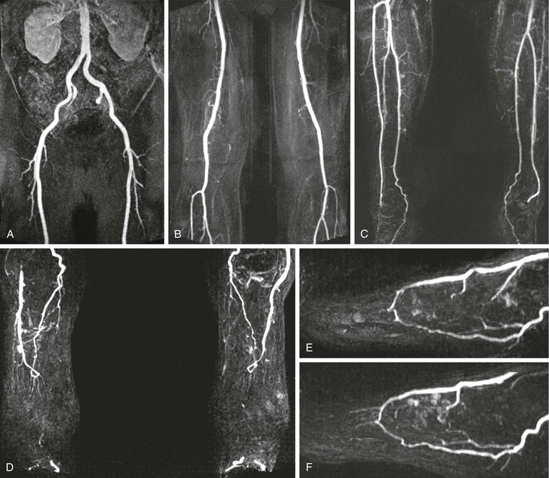
Figure 23-7 Five-station step-table examination showing normal inflow vessels to the lower extremities (A), normal thigh vessels (B), normal calf vessels (C), and normal vessels in both feet (D). The high-resolution 3D data allow reconstruction of each foot in the sagittal plane (E and F), which shows a patent plantar arch in each.
In addition to the value of MRA for diagnosis and pretreatment planning, it may be used for the evaluation of patients after therapy.52–54 MRA can be used to assess graft patency and stenosis. Figure 23-8 demonstrates narrowing at the distal end of a femoral-to-popliteal bypass graft. MRA is also a useful technique for demonstrating complications of graft placement, such as pseudoaneurysm formation, as shown in Figure 23-9.
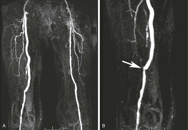
Figure 23-8 A, Coronal 3D thigh-station MR angiogram of a femoral-to-popliteal bypass graft. Note the contralateral disease in the superficial femoral artery. B, An oblique reformatted image shows narrowing at the touchdown of the graft (arrow).
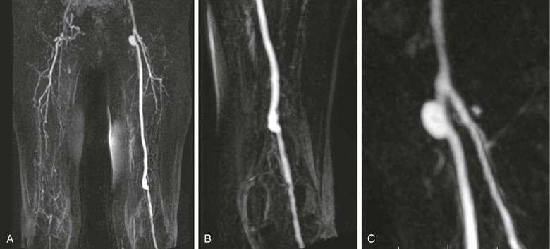
Figure 23-9 A, Coronal 3D thigh-station MR angiogram of a left femoral-to-popliteal bypass graft. Note the contralateral disease in the superficial femoral artery and visualization of multiple collaterals above the right knee. B, An oblique reformatted image shows the distal end of the graft. C, Another oblique reformatted image shows a probable pseudoaneurysm at the origin of the graft.
Carotid Vascular Disease
MRA is becoming an increasingly used method for evaluating carotid artery atherosclerosis. It has proved to be a sensitive method of detecting significant stenoses. For stenosis of between 70% and 99% narrowing, MRA has a reported sensitivity of 95% and a specificity of 90%.55 For all stenoses, MRA has a reported sensitivity of 98% and a specificity of 86%.56 Several authors conclude that the performance of MRA warrants its use as a tool to plan operative or interventional revascularization.57,58 A 3D MR angiogram of the carotid and vertebral arteries is shown in Figure 23-10.
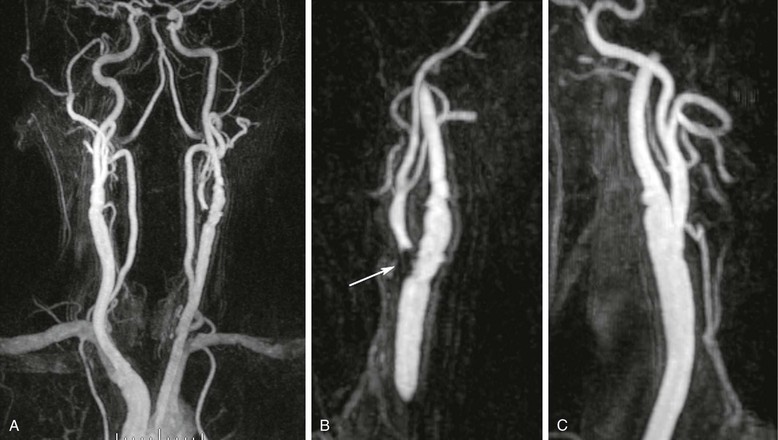
Figure 23-10 A, Coronal 3D MR angiogram of the carotid and vertebral arteries. B, Oblique sagittal reformatted MR angiogram showing high-grade narrowing at the origin of the left external carotid artery (arrow) and mild disease of the left internal carotid artery. C, Oblique sagittal reformatted MR angiogram showing the right carotid bifurcation with only mild disease in the proximal right internal carotid.
Aortic Vascular Disease
Contrast-enhanced 3D MRA has been used to assess the aorta59–62 in patients with many different types of disease. Assessment of the aortic arch by contrast-enhanced MRA may be superior to any other technique.63 Several examples are shown in Figure 23-11. Other diseases that are routinely evaluated by MRA at some centers include aortic dissection,59,64–66 as shown in Figure 23-12, and aneurysms.59,67 MRA is also used to evaluate patients with connective tissue disorders68 (Fig. 23-13) and for aortic stent-graft placement69,70 as well as for endoleak in those with a nitinol-based stent-graft.71,72
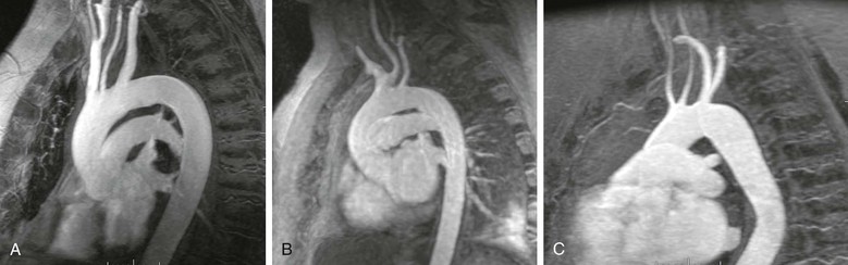
Figure 23-11 A, Sagittal oblique reformatted MR angiogram of a normal aortic arch. B, Sagittal oblique reformatted MR angiogram of a bovine arch. C, Sagittal oblique reformatted image of a rare arch anomaly, bicarotid truncus. All four vessels arise separately from the arch. The carotids arise anteriorly and the subclavians posteriorly.
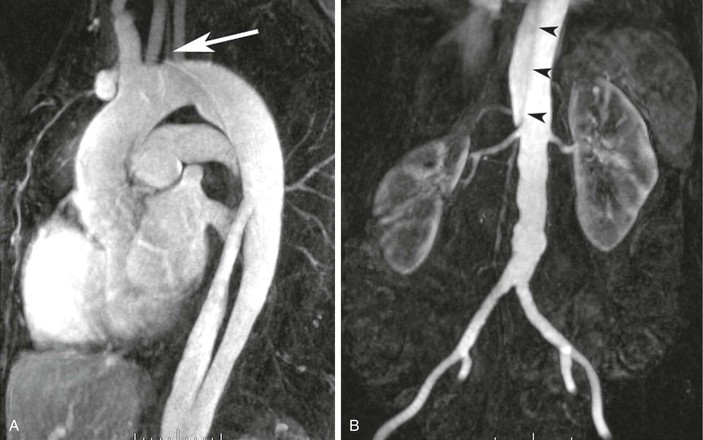
Figure 23-12 A, Sagittal oblique reformatted MR angiogram showing a type B dissection. The origin of the flap and filling of the proximal false lumen are seen. A separate origin of the left vertebral artery is seen from the aortic arch (arrow). B, Coronal 3D MR angiogram obtained during the same examination as the chest-station image by using the step-table technique. The dissection flap (arrowheads) terminates just above the origin of the right renal artery.
Mesenteric Vascular Disease
The most common use of MRA in patients with mesenteric vascular disease is to evaluate those with suspected intestinal angina or chronic mesenteric ischemia.73,74 MRA is between 95% and 97% accurate for characterizing proximal disease of the superior mesenteric artery75 in cases of chronic mesenteric ischemia.
MRA is also useful to evaluate more complex diseases of the mesenteric vasculature. The median arcuate ligament passes anterior to the descending aorta near the T12 level. During end-expiration, the ligament can compress the proximal portion of the celiac axis, which can lead to a false impression of proximal celiac stenosis. MRA can be helpful in demonstrating the effect of the arcuate ligament during a single examination,76 as shown in Figure 23-14.
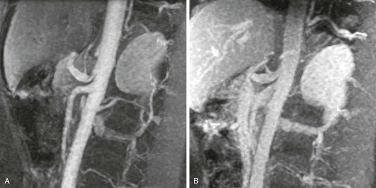
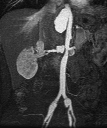
Figure 23-14 A, Arterial-phase sagittal 3D MR angiogram at end-expiration showing the impression of the arcuate ligament just proximal to the origin of the left gastric artery. Notice the quality of the evaluation of the proximal superior mesenteric artery as well. B, Venous-phase sagittal 3D MR angiogram at end-inspiration showing no narrowing of the proximal celiac axis. During the delayed phase, there is still sufficient contrast material within the aorta and branch vessels for adequate visualization.
In cases of suspected mesenteric venous thrombosis, MRV can be an extremely useful tool and has been suggested to be superior to mesenteric catheter angiography.77 MRV is particularly successful because of the ease of detecting small amounts of MR contrast material. Central injection of MR contrast material will be easily visualized in the veins, even after several cycles of circulation. An example of postcontrast 2D MRI is shown in Figure 23-15; the portal vein, splenic vein, superior mesenteric vein, and even inferior mesenteric venous branches occluded with thrombus are clearly depicted.
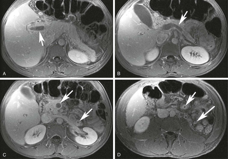
Figure 23-15 A, A 2D T1-weighted postcontrast MR image showing a portal vein thrombus (arrow). B, A 2D T1-weighted postcontrast MR image showing a splenic vein thrombosis (arrow). C, A 2D T1-weighted postcontrast MR image showing superior mesenteric vein and inferior mesenteric vein thrombi (arrows). D, A 2D T1-weighted postcontrast MR image showing small distal branches of the superior mesenteric vein and inferior mesenteric vein filled with thrombi (arrows).
Venous Vascular Disease
MRV is a useful technique for evaluating both central78,79 and deep80–82 venous structures. Central venous structures, in particular the superior vena cava, can be evaluated with 3D methods with 100% sensitivity for the detection of thrombus compared with DSA.79 For pelvic and deep venous structures, it is more common to use 2D TOF angiography.80,81 In cases of suspected deep venous thrombosis (DVT), this method showed that 20% of patients had pelvic DVT that could not be diagnosed by ultrasound.82 This same study also demonstrated that in cases of known pulmonary embolism and negative lower extremity Doppler ultrasound, 29% of patients had residual pelvic DVT.
An example of 2D TOF imaging of an IVC thrombus is shown in Figure 23-16 with corresponding 2D postcontrast MR images. Both types of imaging are useful for detecting DVT in the abdomen, pelvis, and lower extremities.
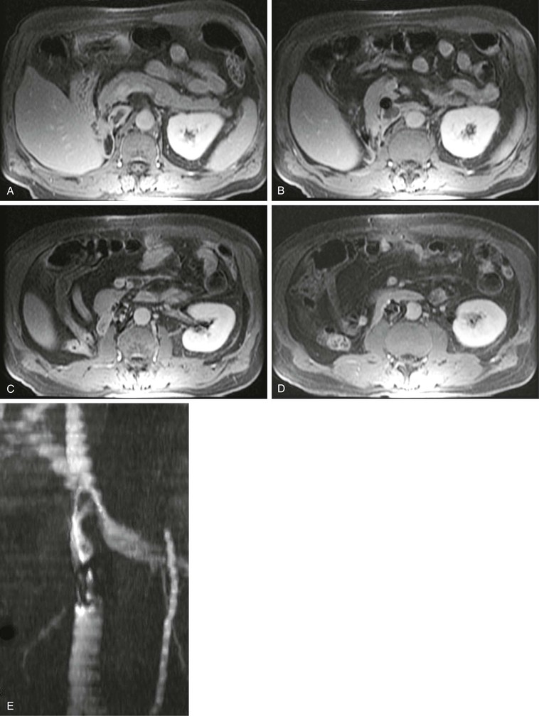
Figure 23-16 A–D, The 2D T1-weighted postcontrast MR images show an IVC thrombus in and superior to an IVC filter. E, Coronal maximum intensity projection of the corresponding stack of 2D time-of-flight images again shows the IVC filter below the left renal vein and the thrombus as a filling defect in the flow extending superiorly.
Other Applications
A large variety of vascular conditions may be evaluated by MRA. The capability of performing the evaluation may depend on the experience of the physicians and technologists performing the study. For example, MRA may be performed to assess patients with suspected thoracic outlet syndrome if the appropriate image sequences can be combined with maneuvers to elicit the symptoms.83 A case of thoracic outlet syndrome is shown in Figure 23-17, where compression of the subclavian vein is clearly seen when the ipsilateral upper extremity is raised above the head.
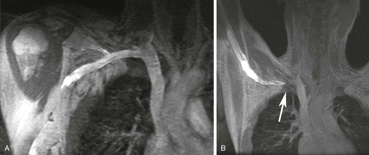
Figure 23-17 A, Coronal 3D MR angiogram showing a normal right subclavian vein with the patient’s arm lowered. B, Coronal 3D MR angiogram showing occlusion of the subclavian vein near the junction with the axillary vein (arrow). Note the pooling of very concentrated contrast material in the arm.
In centers in which transplantation is performed, MRA is useful for assessment of potential renal donors,26,27,39 as mentioned earlier. In addition, MRA can be useful in the assessment of suspected failure of the arterial or venous anastomoses of the transplant graft.5,84 Figure 23-18 demonstrates evaluation of a pancreas transplant graft in the postoperative phase and in a later phase in which graft rejection was occurring.
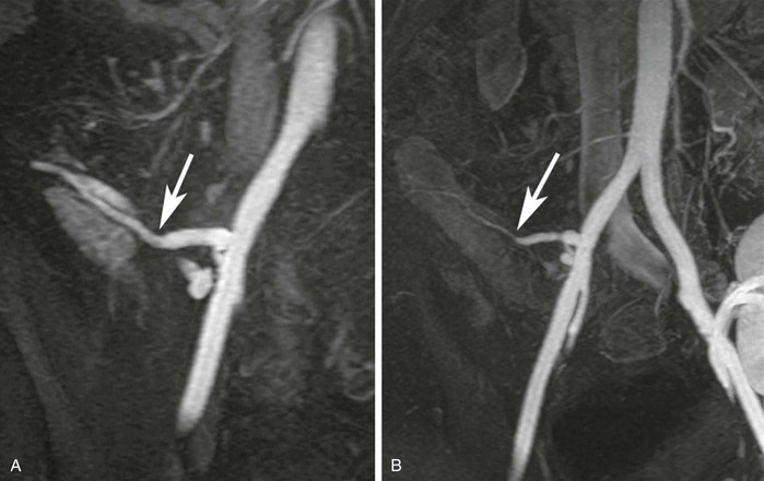
Figure 23-18 A, Coronal 3D MR angiogram showing the anastomosis between the donor external iliac limb of the Y-graft and the donor splenic artery feeding the pancreatic body (arrow). B, Coronal 3D MR angiogram performed later during transplant rejection showing narrowing of the donor splenic artery (arrow). There is also a renal transplant partially seen in the left hemipelvis.
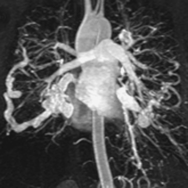
MRA is also useful to assess less common diseases, for example, to diagnose and assess the response to therapy in cases of large-vessel vasculitis.85 An example of Takayasu’s arteritis is shown in Figure 23-19. Another example of more esoteric disease that has easily been assessed by MRA is pulmonary arteriovenous malformations,86,87 as shown in Figure 23-20. In such cases, MRA has 100% sensitivity for imaging pulmonary arteriovenous malformations larger than 5 mm, and all feeding arteries and draining veins are characterized as well.87
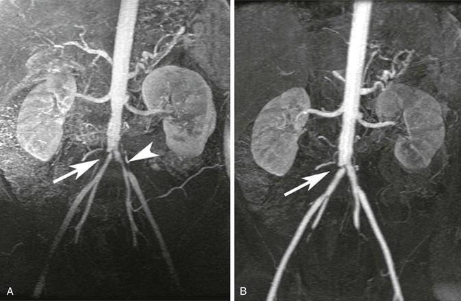
Figure 23-19 A, Coronal 3D MR angiogram showing narrowing of the proximal common iliac arteries bilaterally (arrow and arrowhead) in a patient with Takayasu’s arteritis. B, Coronal 3D MR angiogram showing complete resolution of the left common iliac narrowing and residual disease (arrow) in the right common iliac after treatment.
Limitations and Risks
Scan Artifacts
Several common artifacts and pitfalls are associated with MRA. Knowledge of these limitations will allow the user to approach diagnostic MRA with increased confidence that any abnormal findings do represent actual disease.
Fat Saturation in Chest MR Angiography
Suppressing the signal from fat may be advantageous in that fat will have high signal on the T1-weighted images used for MRA. The so-called fat sat method is an RF suppression pulse that takes advantage of the small difference in resonance frequency between water protons and the protons that are part of long-chain hydrocarbon fat groups. Within the chest, there are intravascular water protons in blood vessels directly adjacent to the lungs. When such geometry exists, the resonance frequency of the water protons may be shifted to the precise range at which the fat protons normally resonate. In this case, the selective method of fat suppression will result in suppression of the water signal instead.88 Thus, a vessel that is entirely patent may appear entirely occluded, or a vessel that is occluded may not be accurately assessed, as shown in Figure 23-21.
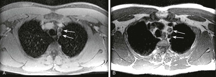
Figure 23-21 A, Axial 2D postcontrast fat-saturated T1-weighted image showing no contrast material within the left subclavian and left common carotid arteries (arrows) in a patient with a type A dissection. B, Axial T2-weighted dark blood imaging showing flow void within the left subclavian but signal within the left common carotid arteries (arrows), findings indicative of thrombosis.
Susceptibility Artifact from Concentrated Gadolinium
MRA contrast material contains a chelated form of the rare earth element gadolinium. The chelate serves several different purposes in the contrast agent. First, it isolates the gadolinium, which is necessary because gadolinium is toxic in its unbound form. Second, the chelate provides multiple binding sites at which surrounding water molecules may remagnetize. Hence, the chelate potentiates the T1 relaxation effects of the gadolinium. However, unbound gadolinium would shorten not only the T1 of water but also the T2 of the surrounding water. The chelate prevents close contact between water and gadolinium, thus minimizing the T2-shortening effects of the gadolinium. However, when the contrast material is at high enough concentrations, there is still a T2-shortening effect that reduces the MR signal. In effect, at high concentrations, MR contrast material behaves like a small piece of metal and produces a susceptibility artifact on the surrounding tissues. These concentrations occur only during the injection of a pure contrast agent and are typically seen in the area of the origin of the great vessels89 or in the subclavian artery during initial passage of injected contrast material through the adjacent vein,90 as shown in Figure 23-22. If this artifact is suspected to be the cause of an apparent stenosis, repeating the sequence immediately should demonstrate resolution because contrast material in the adjacent vein becomes more dilute.
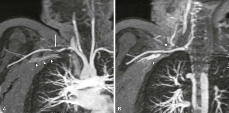
Figure 23-22 A, Arterial-phase coronal 3D MR angiogram showing apparent stenosis (arrow) in the right subclavian artery. Note that the signal from the pure contrast material in the left subclavian vein (arrowheads) is not as high as the signal from the dilute contrast material in the adjacent artery. B, Delayed-phase 3D MR angiogram showing no stenosis in the subclavian artery (arrow). Note that the signal from the dilute venous contrast material is now much higher than that from pure contrast material (arrowhead).
Stay updated, free articles. Join our Telegram channel

Full access? Get Clinical Tree


