22 Left Ventricular Lead Implantation
Cardiac resynchronization therapy (CRT) reduces the chance of hospitalization, improves quality of life, and lowers mortality from congestive heart failure.1–4 CRT requires left ventricular (LV) pacing, usually by a lead placed transvenously through a coronary vein on the epicardium.5–7 Transvenous pacing of the LV epicardium through the coronary venous system can be technically difficult,2,8 but it is safe, and thresholds remain stable.7,9
Transvenous LV lead implantation was new in 1998 and, as with most new therapeutic procedures, required the development of tools and techniques for its safe and cost-effective implementation into clinical practice.10 Because CRT devices were implanted predominantly by electrophysiologist (EP) physicians, their skill set and experience determined the initial tool set. Unfortunately, the EP-suited tools did not overlap well with those useful for LV lead implantation, resulting in a steep learning curve, long case times, and failed implants. Using the EP skill set, pioneering physicians and early adopters eventually developed their own technique, employing a combination of the limited tools designed for the procedure and existing tools that proved useful through improvisation;11–20 however, some patients experienced adverse results.21–25
 Overview
Several notable developments have occurred since the last edition of this textbook. Electronic repositioning in conjunction with bipolar leads (soon to be multipolar leads) has greatly improved success.26 The most important development involves delivery systems.27,28 Telescoping guide support–based delivery systems employ sliceable, preshaped guides for insertion through a separate coronary sinus (CS) access catheter that delivers leads directly to the target vein, allowing for interventional techniques.29,30 Optimal use requires the physician to learn and apply such principles as safe use of contrast, manipulation of open-lumen catheters, effective and efficient injection of contrast, and importance of table position.31
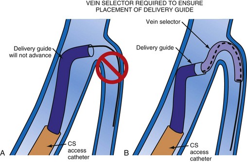
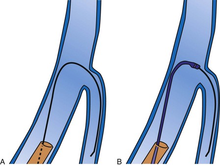
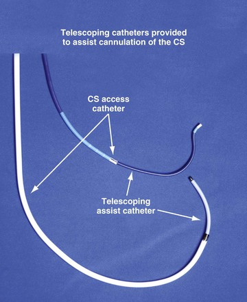
Although an important advance, the new guide support–based delivery systems have two limitations: (1) most do not offer a delivery guide for leads with diameter of 6 to 7 French, and thus only leads 5 Fr (5F) or less usually are deliverable, and (2) most lack a vein selector. A vein selector serves two functions. First, it locates and cannulates the target vein. The design parameters required for a delivery guide, however, limit the ability to locate and cannulate the target vein. It is easier and safer to use a small catheter with a flexible tip to locate the target vein than a catheter designed to provide support for lead delivery. Second, the vein selector provides a rail for the delivery guide. Once the delivery guide locates the vein, it may not be possible to advance into the vein. If a small, flexible-tip catheter is telescoped into the vein through the delivery guide, it can be used as a rail to ensure the tip of the guide engages the vein. The small catheter with a flexible, tapered tip that telescopes through the delivery guide to locate the vein, then act as a rail over which to advance the guide, is a “vein selector” (Fig. 22-1).
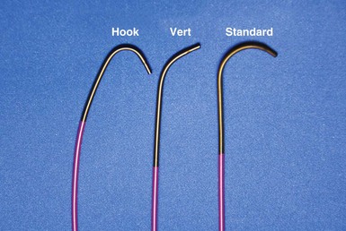
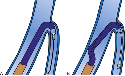
Although catheters from interventional radiology and cardiology can be used as vein selectors, they are the wrong length, the tips are too stiff, and the shapes are not ideal (Fig. 22-2). Fortunately, additional vein selectors are now available in multiple shapes (Fig. 22-3).
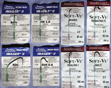
Figure 22-2 Variety of shapes used to locate and cannulate target veins over last decade.
(Courtesy Boston Scientific and AngioDynamics.)
Definitions
Philosophical Approach
This chapter employs the mindset that left ventricular lead implantation should use the most effective tools and techniques to succeed with a transvenous approach. Often this requires tools supplied by more than one vendor and multiple techniques. This approach puts the welfare of our patients first and increases the responsibility of the implanter. If the traditional transvenous approach fails, one option is transseptal, an approach that can be technically difficult and associated with the risk of thromboembolism.32 However, recent studies found a superior hemodynamic performance associated with endocardial compared with epicardial stimulation,33 possibly by allowing access to previously inaccessible pacing sites.34 Our experience in four patients who declined a surgical lead is favorable. Chapter 23 provides a more detailed discussion of transseptal LV lead placement.
Surgical epicardial LV lead placement is covered in the final section of this chapter. Although the surgical approach is an easy way for the implanting physician to complete the procedure,35 “the importance of maximizing the use and safety of transvenous approaches is stressed because while the electrical and functional limitations of trans-CS LV epicardial coronary vein leads are well publicized, the limitations of available transthoracic, transepicardial, and true epicardial electrodes may be less appreciated,”36 with 15% LV lead failure at 5 years.37 In addition to lead failure, lead position, morbidity, and mortality must be considered. Utilizing pressure-volume loops, Dekker et al.38 found epicardial sites that “did not significantly change left ventricular function and even worsened it in some cases.”38 If surgical placement is attempted, the surgeon needs the same dedication as the implanting physician to place the LV lead in the appropriate location with good thresholds.
Although data are limited, without a prospective randomized comparison, complications and mortality appear to be much higher than the transvenous approach.39–41 In the series by Ailawadi et al.,39 the mortality was double, and postprocedural complications of acute renal injury (26.2% vs. 4.9%; P < .001) and infection (11.9% vs. 2.4%; P < .03) were more common in the surgical group. Based on analysis of the Replace Registry, surgical LV lead mortality may be greater than 8%; 48 patients (11% of 434 attempted LV lead placements) had a failed EP lab attempt. There were four deaths in the patients sent for surgical epicardial LV placement. Assuming every patient with a failed attempt went to surgery for an epicardial lead, the mortality is 8%.40 However, we do not know how many of the 48 were actually sent for an epicardial lead, or if the patients who required surgical intervention were similar to those who did not.
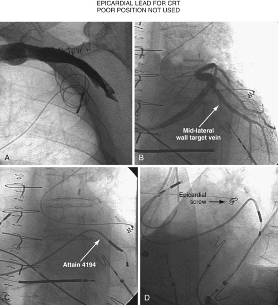
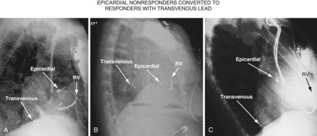
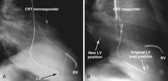
Figure 22-4 is from a patient who underwent lead placement through an epicardial approach, showed no response, and then experienced improvement with a transvenously placed lead. Figure 22-5 contains the lateral chest radiographs of three patients who had failed transvenous implants, then did not respond to an epicardial lead, but improved when a lead was placed transvenously using guide-based delivery system and interventional techniques. If the patient is to be exposed to surgical risk, it is important to insist that the surgically placed leads are located on the midlateral free wall.
 Left Ventricular Lead Position and Response
As mentioned earlier, not only does cardiac resynchronization therapy require pacing of the left ventricle, but the location of the lead can be important as well.38,42 The midlateral wall of the left ventricle usually is the best location for an LV lead. When considering whether a patient is not responding to CRT, lead position can be important. The left anterior oblique (LAO) view on fluoroscopy at implantation should define the LV lead position. However, if the fluoroscopy is not performed in a standard manner, it can be deceptive. Kistler et al.43 describe a case in which electrocardiographic analysis showed that a lead fluoroscopically thought to be in the left ventricle at implantation was actually in the right ventricle.
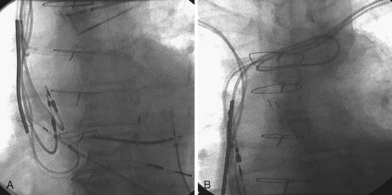
Another example of fluoroscopic error is shown in Figures 22-6 and 22-7. The LAO fluoroscopic image in Figure 22-6, A, appeared to document a lateral position. However, the lateral chest radiograph demonstrated the anterior location (Fig. 22-6, B). In Figure 22-7, A, the steeper LAO projection reveals the anterior nature of the first (“nonresponder”) LV lead position. It is important for the implanting physician to take personal responsibility for reviewing the final location of the LV lead, to ensure that the patient has received the best possible lead position. In follow-up of patients after implantation, we demonstrated that the left ventricular (LV)–right ventricular (RV) lead separation on the lateral chest radiograph is essential in evaluating “nonresponders” in whom LV lead placement has been “successful.”44 Heist et al.45 demonstrated that the acute hemodynamic effect of CRT is predicted by the LV-RV interlead distance, as measured on the lateral chest radiograph after the procedure. Placement of the LV lead on the anterior surface of the left ventricle is at best suboptimal, resulting in deteriorating LV function in some patients regardless of the method of implantation.38 Unless convincing, specific information to the contrary is available, the midlateral free wall of \the left ventricle appears to be the optimal position for the LV lead. When the LV lead is on the midlateral wall, its position on a lateral chest radiograph is directly posterior. Figure 22-8 shows the typical postimplantation chest radiographs of a “responder” in whom the LV lead is located on the midlateral wall of the left ventricle. Note that the LV and RV leads are maximally separated on the lateral chest radiograph.
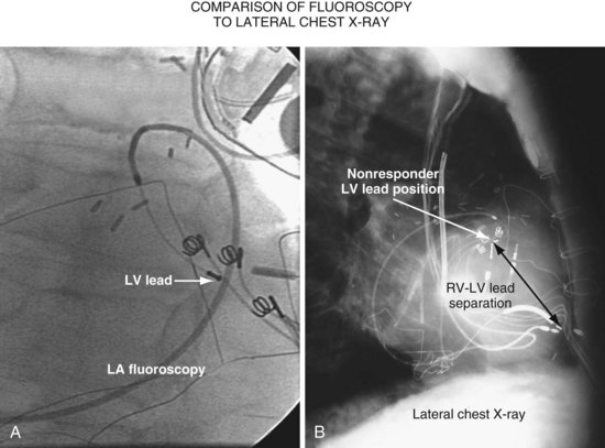
Figure 22-6 Fluoroscopy and chest radiography at initial implantation of left ventricular (LV) lead.
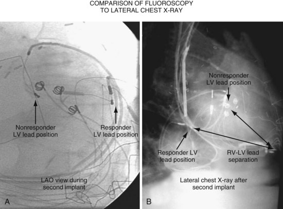
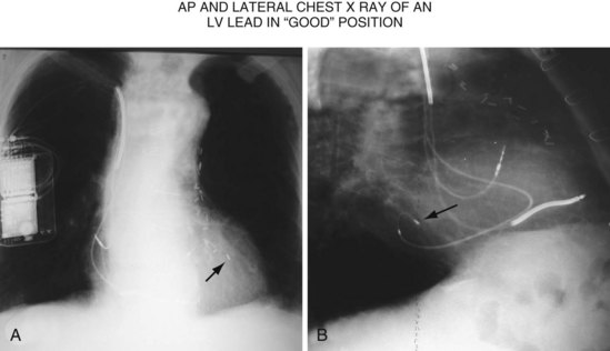
Figure 22-8 Chest radiographs of patient showing response to cardiac resynchronization therapy (CRT).
Figure 22-9 includes the lateral chest radiographs of two patients who showed no response to CRT with their original lead position but did respond when a lead was positioned on the midlateral free wall. Figure 22-9, A, is the lateral chest radiograph of a nonresponder in whom the lead was placed in the anterior interventricular vein; patients with a lead in this location are not expected to show response. Figure 22-9, C, however, is the lateral chest radiograph of a patient who showed no response even though the LV lead had been placed in the vein to the midlateral free wall. What happened? The LV lead is advanced distally in the midlateral vein, which wraps around anteriorly toward the septum. Although the lead started in the vein to the midlateral free wall, it ended up anterior, close to the RV lead. Note that in Figure 22-9, A and C, the tip of the LV pacing lead is closer to the RV pacing lead than the ideal position seen in Figure 22-8, B. When a second LV lead was placed, this time on the lateral wall (Fig. 22-9, B and D), the patients improved clinically and were regarded as “responders.”
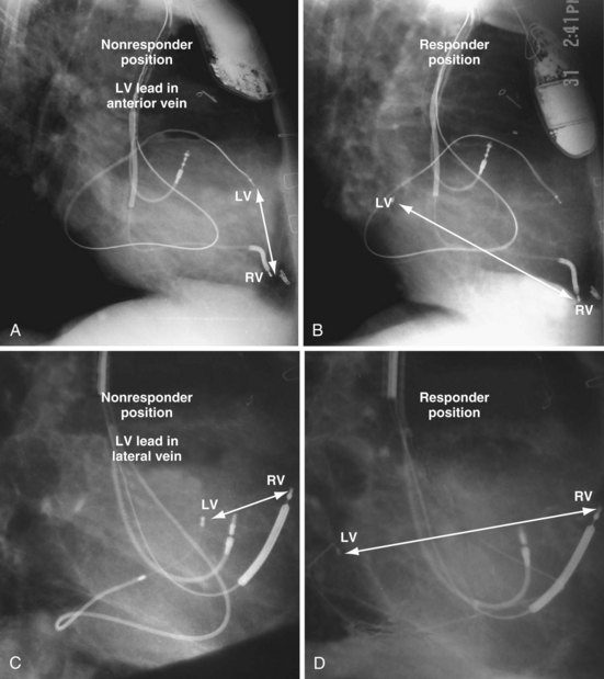
Figure 22-9 Chest radiographs of CRT nonresponders versus responders.
A, Anterior left ventricular (LV) lead is in the anterior vein. B, New lead is placed in a lateral vein, converting a CRT nonresponder to a responder. C, The lead starts in the lateral wall target vein but is advanced distally, which places the tip anterior (not apical) well beyond the ideal location. In both A and C, the physical separation between the right ventricular (RV) and LV leads (white arrows) is small. In both patients, new leads were placed (B and D) in positions similar to those shown in Figure 22-8, with marked improvement in symptoms. In the patient in C and D the new LV lead was placed more proximal in the same vein.
The clinical question raised is whether repositioning the LV lead of the patient in Figure 22-9, C, to a more proximal position in the same vein, thus increasing the RV-LV separation, would change a nonresponder to a responder. Figure 22-10 illustrates the original and new, more proximal positions in the same vein of a patient in whom such repositioning was performed. The RV-LV lead separation was increased, and the patient demonstrated a marked symptomatic improvement, objectified by reductions in both serum creatinine level and dose of diuretics.
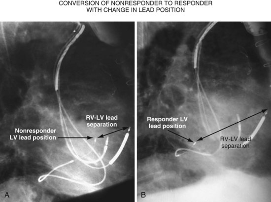
Figure 22-11, A, is the lateral chest radiograph of a patient in whom the original implanting physician was not prepared to perform coronary vein venoplasty. The vein to the midlateral wall was distal to a stenosis in the main body of the CS. Although the implantation was regarded as “successful,” the pacing lead was not placed on the midlateral wall of the left ventricle. The patient did not improve after the procedure, was regarded as a CRT “nonresponder,” and listed for heart transplantation. He was evaluated at our facility, where the lead position on the lateral chest radiograph was discovered. He subsequently underwent venoplasty of the main body of the CS, and the lead was placed on the lateral wall of the left ventricle (Fig. 22-11, B); dramatic resolution of symptoms eliminated the need for a heart transplant. Both the acute hemodynamic effect and the subsequent clinical response to CRT are predicted by the RV-LV lead separation on the lateral chest radiograph. On the basis of the work of Heist et al.,45 the RV-LV separation in the horizontal plane is more important than the total RV-LV separation, and the RV-LV separation in the vertical plane was not predictive.
 Guide Support–Based Delivery System
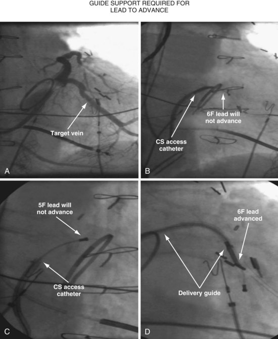
Since 1997, LV pacing leads have evolved from unipolar 6F stylet-driven to quadripolar 5F over-the-wire leads. Despite improvements in LV pacing leads, their placement continues to be limited by the coronary venous anatomy. Frequently, guide support is required because the angioplasty wire does not provide adequate support to advance the LV lead into the vein (Fig. 22-12). Guide support is present when the tip of the guide rests securely within the target vein and the back of the guide is supported by the coronary sinus, as occurs with a catheter where the tip is preshaped specifically to cannulate the target vein, not the CS. The magnitude of support provided by the preshaped guide depends on its shape, as shown in Figure 22-13; the compound shape in B offers greater support than the single curve in A because the secondary curve is supported by the CS back wall.
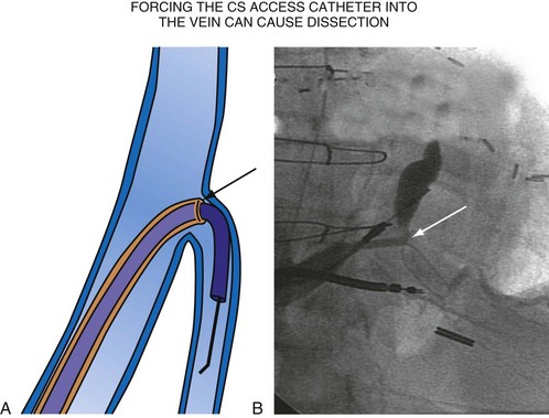
For the purposes of this chapter, a delivery guide is defined as a braided, slittable catheter preshaped for LV lead delivery (not for CS access) that is inserted through a separate catheter in the CS. A CS access catheter is defined as a removable catheter designed specifically for CS cannulation and to provide a platform for LV lead delivery. CS access catheters can occasionally provide guide support when it inadvertently cannulates the target vein or is forced into the vein. Forcing a CS access catheter requires an angle of less than 30 degrees, a situation where guide support is usually not required. Furthermore, the potential exists for dissection as the straight tip of the CS access catheter is forced around the curve (Fig. 22-14).
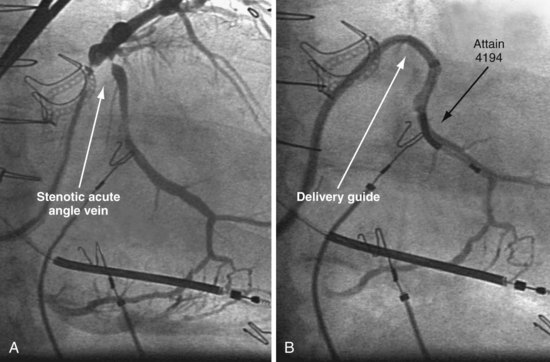
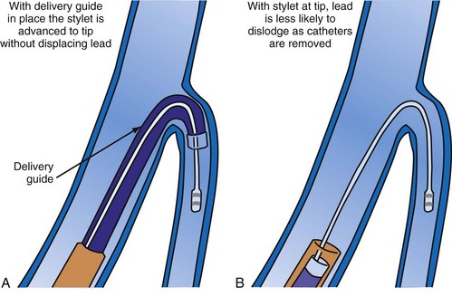
A delivery guide is the most reliable way to deliver a lead to the target vein, particularly when the anatomy is difficult (Fig. 22-15), but also even when the anatomy seems favorable (Fig. 22-16). In addition, the delivery guide makes it easier to deal effectively with lead instability, high thresholds, and phrenic pacing; inject contrast to identify branches; provide support to reposition the lead; or change to a lead of different size or shape and to a different method of fixation. Lastly, because the delivery guide allows the stylet to be safely advanced to the tip (Fig. 22-17), the final step of removing catheters from the CS is less likely to displace the lead. Accordingly, the approach to LV lead implantation described in this chapter is based on using a guide support–based delivery system.
Shape and Use of Delivery Guides
Previous Approach
In the third edition of this book, I emphasized matching delivery guide shape to the target vein anatomy for two reasons. First, at that time we used either interventional guides from radiology or the first-generation Pressure Products delivery guide (Fig. 22-19, A). Both had very firm tip sections, which could not be advanced into the target vein or did not remain stable once advanced (Fig 22-20). However, with the new soft-tip design (Fig. 22-19, B), the Pressure Products delivery guide can be advanced deep into the target vein and remains stable.
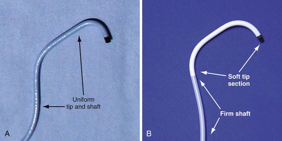
Figure 22-19 Comparison of tip section of original and current delivery guides.
(Courtesy Pressure Products, San Pedro, Calif.)
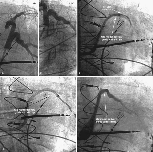
Figure 22-20 Stiff tip prevents secure advancement of interventional and delivery guides into target vein.
Second, it initially appeared that the delivery guide could be used reliably to locate the vein, advance the wire, and then be advanced over the wire into the vein. Although effective in some cases, we found that the delivery guides were not optimal for small or off-axis target veins, necessitating the addition of a small, diagnostic catheter telescoped through the delivery guide (see Fig. 22-1). It thus became clear that a small diagnostic catheter (vein selector) was an essential component of a guide support–based delivery system and needed to be included with the delivery guide (see Fig. 22-3).
New Approach
Recognizing that a vein selector will be needed to locate and cannulate the target vein in at least some cases, and that the soft tip of the new Pressure Products delivery guide can be advanced to a stable position deep in the vein if needed, we now rely on the shape of the vein selector for off-axis and difficult veins and use a single shape of delivery guide. Using the included vein selector and wire(s) as a rail the “renal” delivery guides can be inserted into the vast majority of target veins, regardless of takeoff (Fig. 22-21). We rarely if ever use one of the other shapes of Pressure Products delivery guides (hook, hockey stick, or multipurpose). The vein selectors also work in the same manner with the device company delivery guides.
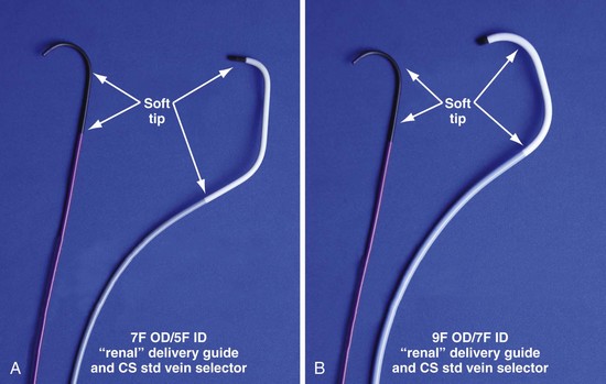
Figure 22-21 Renal-shaped delivery guides with vein selector.
A, The 7-French (7F) “renal” delivery guide is shown with the included 5F standard vein selector (Telescopic Braided Renal LVI 75-5-66-55-RE, Pressure Products). It has a 7F outer diameter (OD), 5.5F inner diameter (ID), and a working length of 66 cm. B, The 9F OD renal delivery guide is shown with the included 5F standard (std) vein selector (Telescopic Braided Renal LVI 75-5-62-07-RE). It has a 9F OD, 7F ID, and working length of 63 cm. The soft tip section of the delivery guide can be advanced deep into a target vein over the vein selector, if needed. As a result, we now rely on the shape of the vein selector, not the shape of the delivery guide, to accommodate the takeoffs of various veins. When used with a vein selector, the renal-shaped delivery guide is suitable for the vast majority of cases. In approximately 10% of cases, one of the other two vein selectors (Impress CS Vert p/n 1628-017 or Impress CS Hook p/n 1628-019, Merit Medical; see Fig. 22-3) may be required to locate and cannulate the target vein.
 Left Ventricular Lead Implantation with Interventional Techniques
Step-By-Step Summary
Details and Rationale
This section describes my recommendations for implanting LV leads and the tools used. Chapter 23 describes more advanced interventional technique, including crossing total occlusions, subclavian and coronary vein venoplasty, using balloons as anchors, and use of snares. With these techniques, we have successfully implanted all 27 patients with failed implants referred from other centers, including five who had epicardial leads but did not respond.
Prepare Patient for Iodinated Contrast Material
The safe use of contrast is discussed in detail in Chapter 23. In summary, contrast improves safety, reduces implant time, and is essential to the use of a guide support–based delivery system. Rather than only trying to limit contrast, it is better to take steps to prevent nephropathy. Use of contrast can then be individualized; many patients will be at relatively low risk, whereas others (e.g., diabetics with increased creatinine) remain at high risk. Because the serum creatinine can vary substantially in CRT patients depending on volume status, we recommend hydration for all patients as follows:
Equipment and Room Setup
Collect Available LV Lead Implantation Equipment and Review Its Use
The worst mistake may be to assume that the equipment required for a successful efficient LV lead implantation either is in the room or has been provided by the manufacturer. Some of the equipment is readily available in the hospital but is not part of the usual repertoire of many implanting physicians. Knowledge of the equipment used in interventional radiology and interventional cardiology can be extremely useful during an LV lead implantation (see Interventional Implant Equipment List at end of chapter). The technical staff and physicians from interventional cardiology and radiology often have helpful suggestions for solving the mechanical problems posed by an LV lead implantation, and equipment specifically tailored to LV lead placement is slowly making its way into the world of electrophysiology. Access to these new tools can make the difference between an easy success and a painful, demoralizing failure.
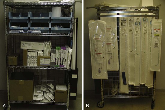
Organize Equipment to be Readily Available in Room
It is important to remember that the interventional implant equipment needed is not usually available in a room used for either pacer implantation or an EP study. To avoid spending more time surveying the interventional cardiology and radiology laboratories than actually working on the patient, the physician should make certain of having the most basic equipment in the room. These tools are additional to the device company equipment and sheaths used for pacemaker implantation. To be certain we have the proper tools regardless of the room, our staff created a “BiV Cart.” This cart also contains equipment for performing subclavian and coronary vein venoplasty (Fig. 22-22).
Assemble “Always Used” Equipment on Table before Starting
Having a routine and setting the table with equipment needed for the procedure give the operator the freedom to concentrate on the procedure and help avoid “rethinking” the tools for each implantation (Fig. 22-23).
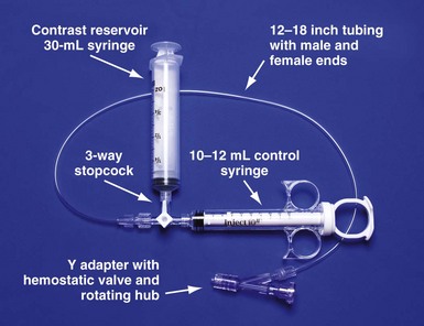
Figure 22-23 Simplified system to allow assistant to inject contrast while operator manipulates catheter with both hands.
For right-handed operator, the right hand is on the rotating hub on the Y adapter, and the left hand is on the catheter. The system is used to inject contrast for location of the coronary sinus os, for the occlusive venogram, and for locating the target vein with the vein selector. The system can be constructed from equipment readily available in most laboratories and is available as a kit (Pressure Products or Merit Medical; see equipment list at end of chapter for details). The scrub technician should have the pieces on the table and assembled before notifying the implanting physician to scrub for surgery.
Pay Careful Attention to Orientation of Instrument Table During Procedural Stages
It is remarkable how important the position of the instrument table can be to a successful implantation. It is even more remarkable how frequently even an experienced implanter forgets to change to a table position appropriate to the stage of the procedure until either the support staff provides a gentle reminder or something that should be easy feels difficult. Figure 22-24, A, demonstrates the usual “backfield” position of the instrument table. We keep the table in this position until we start CS access, at which point the table is turned perpendicular to the patient (Fig. 22-24, B). Once the LV lead is in place and it is time to start removing the guide and sheath, the table is returned to the backfield position so the assistant can support the sheath and lead during sheath and guide removal.
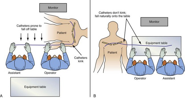
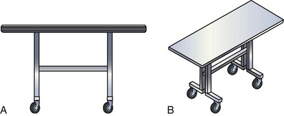
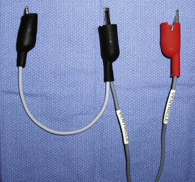
The custom-built table shown in Figure 22-25 addresses all three issues. The legs are recessed to provide room for the fluoroscopy unit, the operator’s feet, and fluoroscopy pedals. The height is adjustable so that the top of the table can be raised to reduce the vertical stepoff between the patient and the table. Interventional principles teach that when working with catheter, it is important that the implant table be turned perpendicular to the patient table (T-bone position) so that the wires and catheters exit the body falling naturally onto the table (see Fig. 22-24, B). Further, the assistant is in the optimal position to assist with the catheter manipulation, contrast injection, and wire exchanges required for LV lead implantation and the use of balloons. Application of torque to the catheters is not lost in a right angle, and the open-lumen catheters are not prone to kink. Testing the left and right ventricles simultaneously for pacing thresholds can be difficult with standard testing cables. Simply attaching an additional alligator clip eliminates this problem (Fig. 22-26).
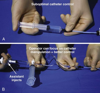
Approach to Contrast
An important point frequently overlooked is the approach to contrast injection. EP physicians accustomed to working alone with solid catheters naturally try to inject contrast and control the catheter. However, interventional principles clearly show that catheter control is degraded when one hand is removed from the catheter and attention is turned to contrast injection. Suboptimal catheter control will result in increased use of contrast and a greater chance of misadventure. For optimal catheter control, the operator keeps both hands on the catheter and attention focused on tip position (Fig. 22-27).
Venous Access
Preventing Restricted Catheter/Lead Movement
Separate Access for Each Lead
Having separate access sites for each lead reduces the interaction among the three leads. If only two access sites can be obtained, the RV and RA leads should be placed through the same access site to minimize the potential for movement of either lead to displace the LV lead. When leads share the same access, friction between the two may result in the stable lead being withdrawn by manipulation of the other lead. To help prevent lead withdrawal, keep the stylet of the stable lead at the junction between the inferior vena cava (IVC) and superior vena cava (SVC) until manipulation of both leads is complete, even after the stable lead is tied down. Without a stylet, the stable lead can withdraw, even when tied to the muscle, by forming an S configuration within the subclavian vein distal to the tie-down (Fig. 22-28).