Intravascular Imaging Techniques
Yasuhiro Honda
Peter J. Fitzgerald
Paul G. Yock
Angiography remains the clinical standard for coronary and peripheral vascular imaging to identify significant arterial narrowing and to guide both catheter-based and surgical interventions. Although angiography provides a highly useful picture of the vessel lumen, it offers only indirect information about the arterial wall. The advanced catheter-based imaging tools described in this chapter—intravascular ultrasound, optical coherence tomography, angioscopy, and spectroscopy—provide supplemental and unique insights into vascular disease and the mechanism of therapeutic intervention.
INTRAVASCULAR ULTRASOUND
Intravascular ultrasound (IVUS) catheters use reflected sound waves to visualize the arterial wall in a two-dimensional, tomographic format, analogous to a histologic cross section. They utilize significantly higher frequencies than utilized in noninvasive echocardiography (20 to 45 MHz as compared with 2 to 5 MHz). This provides high resolution (100 to 200 µm for the coronary catheters) at the expense of beam penetration (limited to 4 to 8 mm from the catheter tip). Since the initial clinical experience with IVUS in 1988,1 this technique has gained acceptance both as a research method and as a clinical tool for situations in which the angiogram is unclear or unable to make precise measurements via visual estimate or computer-assisted techniques.
Imaging Systems
There are two approaches to IVUS imaging: solid state dynamic aperture and mechanical scanning. Both approaches generate a 360°, cross-sectional image plane perpendicular to the catheter tip. In the solid state approach, the individual elements of a circumferential array of multiple transducers mounted near the tip of the catheter are activated with different time delays to create an ultrasound beam that sweeps the circumference of the vessel. As the number of elements has increased, there have been progressive improvements in lateral resolution. Complex miniaturized integrated circuits in the catheter tip control the timing and integration of the transducer activation and route the resulting echo information to a computer where cross-sectional images are reconstructed and displayed in real time. In the mechanical approach, a single transducer element is rotated inside the tip of a catheter via a flexible torque cable spun by an external motor drive unit attached to the proximal end of the catheter. Images from each angular position of the transducer are collected by a computerized image array processor, which synthesizes a cross-sectional ultrasound image of the vessel.
The latest solid state coronary catheter system (Volcano Corp., San Diego, CA) has 64 transducer elements arranged around the catheter tip and uses a center frequency of 20 MHz. The current coronary catheters in a rapid-exchange configuration are 3.5F at the largest dimension (transducer assembly) and thus compatible with a 5F guide catheter. Larger peripheral imaging catheters are produced in both over-the-wire and rapid-exchange configurations. A 10F phased-array catheter for intracardiac echo (ICE) imaging (Siemens Medical Solutions USA, Inc., Malvern, PA) uses a unique technology adapted from transesophageal echocardiography, providing a sector ultrasound image with color and spectral Doppler capabilities. The catheter is compatible with multiple-frequency imaging (5.0 to 10 MHz) so that the operator can determine the desired trade-off between resolution and penetration (up to 15 cm).
Mechanical IVUS systems are available from several manufacturers in slightly varying configurations (Volcano Corp.; Boston Scientific Corp., Natick, MA; Terumo Corp., Tokyo, Japan). The current coronary catheters use a 40 or 45 MHz transducer and are 3.2F to 3.5F at the largest dimension, compatible with a 6F guide catheter. Larger catheters with lower center frequencies are also available for peripheral and ICE imaging. The catheters are advanced over a guide wire using a short rail section at the catheter tip, located
beyond the imaging-window segment within which the spinning transducer may be advanced or withdrawn. To improve the trackability and pushability, one manufacturer provides an imaging catheter with a second long rail section located proximally in addition to the standard short rail section at the catheter tip (Terumo Corp.). In mechanical systems, the fact that the guide wire runs outside the catheter parallel to the imaging segment results in a shadow artifact in the image.
beyond the imaging-window segment within which the spinning transducer may be advanced or withdrawn. To improve the trackability and pushability, one manufacturer provides an imaging catheter with a second long rail section located proximally in addition to the standard short rail section at the catheter tip (Terumo Corp.). In mechanical systems, the fact that the guide wire runs outside the catheter parallel to the imaging segment results in a shadow artifact in the image.
In head-to-head comparisons, mechanical systems have traditionally offered advantages in terms of image quality, as compared to the solid-state systems, owing to their higher center frequencies and the larger effective aperture of the transducer element. Particularly, near-field resolution is excellent with mechanical catheters so that digital subtraction of the ring-down artifact is not required. In addition, a stationary outer sheath of mechanical catheters allows the transducer to be moved through a segment of interest in a precise and controlled manner. On the other hand, the longer rapid-exchange design of the solid-state catheter may track better than the short rail design of mechanical systems in complex coronary anatomy. The distance from the transducer to the catheter tip is shorter than that of mechanical systems, which may also be beneficial in IVUS-guided intervention of chronic total occlusion (CTO) lesions. The solid-state catheter includes no moving parts, and thus is free of non-uniform rotational image distortion (NURD). This artifact can occur with mechanical systems when bending or friction of the drive cable interferes with uniform transducer rotation, causing a wedge-shaped, smeared image to appear in one or more segments of the image (Figure 25.1). With both systems, serial cross-sectional images can be reconstructed into a longitudinal display mode, and both still frames and video images can be digitally archived on local storage memory or a remote server using Digital Imaging and Communications in Medicine (DICOM) Standard 3.0. Both systems can be installed directly into the cine angiogram system, enabling operators to quickly and easily incorporate IVUS interrogations into their interventional procedures.
Image Acquisition Procedures
The image integrity of the IVUS system should be checked before inserting the catheter. Mechanical catheters require flushing with saline to remove air bubbles from inside the catheter. This preparation should be performed before inserting the IVUS catheter to avoid air embolism in the coronary artery. Residual microbubbles within the protective sheath can result in poor image quality once the catheter is inserted (Figure 25.1). Solid state catheters require an extra step to mask “ring down” artifact prior to being inserted into the coronary artery. This masking process is accomplished while positioning the catheter tip free in the aorta.
IVUS examination should be performed with intravenous administration of heparin (5,000 to 10,000 unit) or equivalent anticoagulation (an activated clotting time of >250 seconds is recommended). Intracoronary nitroglycerin (100 to 200 µg) should also be routinely administered prior to the delivery of the IVUS catheter in order to induce maximal vasodilation and to prevent vasospasm. Using standard interventional techniques with a 0.014 inch angioplasty guide wire, the imaging probe is advanced at least 10 mm distal to the area of interest under fluoroscopic guidance. The length of the target vessel is then scanned by retracting the transducer within a stationary outer sheath (mechanical IVUS) or by moving the catheter itself (solid state IVUS). Unless the patient complains
of chest discomfort or myocardial ischemia is suspected, the image acquisition is recommended to include distal vessel, lesion site, and the entire proximal vessel, back to the aorta. For comparison with repeated studies, identifiable landmarks such as major side branches may be used as a fixed starting point of imaging. Accurate evaluation of the aorto-ostial segment requires that the guide catheter be disengaged slightly from the ostium.
of chest discomfort or myocardial ischemia is suspected, the image acquisition is recommended to include distal vessel, lesion site, and the entire proximal vessel, back to the aorta. For comparison with repeated studies, identifiable landmarks such as major side branches may be used as a fixed starting point of imaging. Accurate evaluation of the aorto-ostial segment requires that the guide catheter be disengaged slightly from the ostium.
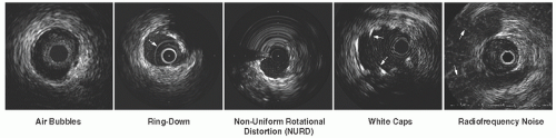 Figure 25.1 Common IVUS image artifacts. Air bubbles can cause a high echoic noise around the imaging catheter with image deterioration. Ring-down artifacts seen as a series of bright rings around the mechanical IVUS catheter (arrow) can also be caused by air bubbles, which need to be flushed out. Non-uniform rotational distortion (NURD) results in a wedge-shaped, smeared appearance in one or more segments of the image (between 9 and 4 o’clock in this example). White cap artifacts caused by side lobe echoes (arrows) originate from a strong reflecting surface, such as metal stent struts or calcification. Smearing of the strut image can lead to the mistaken impression that the struts are protruding into the lumen. Radiofrequency noise (arrows) appears as alternating radial spokes or random white dots in the far-field. The interference is usually caused by other electrical equipment in the cardiac catheterization laboratory. |
Image Interpretation
Interpretation of the images begins with the identification of two key landmarks: the blood/intima (luminal) border and the media/adventitia interface (Figure 25.2). The luminal border is the first bright interface beyond the catheter and is generally easy to locate on IVUS images. However, blood within the lumen exhibits a speckled low-intensity pattern, which is more prominent at higher ultrasound frequencies and may make recognition of the intimal border more difficult. Signal-processing software can color code or subtract the blood signal so that it does not obscure the intimal interface. If the blood signal is still confusing, saline can be injected through the guide catheter to reduce blood speckle and help delineate the true lumen border.
The second key IVUS landmark is the media/adventitia border. In muscular arteries such as the coronary tree, the media may stand out as a thin dark band since it contains much less echo-reflective material (collagen and elastin) than contained by the neighboring intima and adventitia. This provides a characteristic three-layered (bright-dark-bright) appearance on IVUS images.2 However, the stronger echo reflectivity of the intimal layer often causes a spillover effect, known as blooming, resulting in a slight overestimation of the intimal thickness with a corresponding underestimation of the medial thickness. Also, this three-layered appearance may be undetectable in truly normal coronary arteries wherein the intimal thickness is below the effective resolution of IVUS.
In atherosclerotic disease where the media has been destroyed, the media may not appear as a distinct layer around the full circumference of the vessel. In the proximal vessel segments and at branch points, the media contains relatively high amounts of collagen and elastin, frequently causing it to blend with the surrounding layers. Even in such cases, however, the boundary between the outer media and adventitia (the outer perimeter of plaque-plus-media zone) is generally identifiable owing to a step-up in echo reflectivity at this boundary without blooming. In most cases, the IVUS beam penetrates beyond the arterial wall, providing images of perivascular structures such as the cardiac veins, myocardium, and pericardium (Figure 25.3). These structures have characteristic appearances when
viewed from different positions within the arterial tree and can provide useful landmarks regarding the position of the imaging plane.3
viewed from different positions within the arterial tree and can provide useful landmarks regarding the position of the imaging plane.3
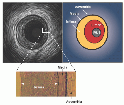 Figure 25.2 Cross-sectional format of a typical IVUS image. The bright-dark-bright, three-layered appearance is seen in the image with corresponding anatomy as defined. “IVUS” represents the imaging catheter in the blood vessel lumen. Histologic correlations with intima, media, and adventitia are shown. The media has lower ultrasound reflectance owing to less collagen and elastin as compared with the neighboring layers. Because the intimal layer reflects ultrasound more strongly than does the media, there is a spillover in the image, which results in a slight overestimation of the thickness of the intima and a corresponding underestimation of the medial thickness. |
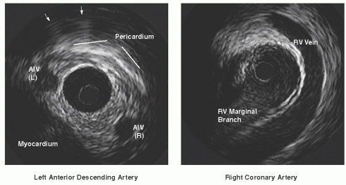 Figure 25.3 Perivascular landmarks. On a distal cross-section of the left anterior descending artery (left), the right and left branches of the anterior interventricular vein (AIV) are seen framing the coronary artery. The pericardium appears as a bright arc with spokes emitting from it (arrows). On a cross-section of the mid right coronary artery (right), bridging veins arch over the artery, typically at a position adjacent to the right ventricular (RV) marginal branches. |
Quantitative Assessment
Unlike coronary angiograms, IVUS has an intrinsic distance calibration, provided as a grid on the image or tag information of DICOM files. Electronic caliper (diameter) and tracing (area) measurements can be performed at the tightest cross section (maximum stenosis), as well as at reference segments located proximal and distal to the lesion4 (Figure 25.4). In general, the reference segment is selected as the most normal-looking (largest lumen with smallest plaque burden) cross section within 10 mm from the lesion with no intervening major side branches.
Vessel and lumen diameter measurements are important in everyday clinical practice where accurate sizing of devices is needed. The maximum and minimum diameters (the major and minor axes of an elliptical cross section) are the most widely used. The ratio of maximum to minimum diameter defines a measure of symmetry. Area measurements are performed with computer planimetry. Lumen area is determined by tracing the leading edge of the blood/intima border, whereas total vessel (or external elastic membrane, EEM) area is defined as the area enclosed by the outermost interface between media and adventitia. Plaque area (or more accurately, the plaque plus media area) is calculated as the difference between vessel and lumen areas; the ratio of plaque area to total vessel area is termed the percent plaque area, plaque burden, or percent cross-sectional narrowing.
Metal struts of stents are seen as bright, focal points in a circular-arrayed pattern on the IVUS scan, and the stent measurement is performed at the leading edge of stent struts in the same way as done in non-stented segments. Neointimal hyperplasia within the stent has low echo-reflectivity at follow-up IVUS imaging, and the area is calculated as the difference between stent area and lumen area. Area measurements can be added to calculate volumes using Simpson’s rule with the use of motorized pullback. For standardized data expression, the volume is presented as a volume index or average area, calculated as the absolute volume divided by the length of the analyzed segment.
Arterial remodeling, originally described by Glagov et al. for necropsy specimens,5 is a bidirectional vessel response represented as the increase or decrease in vessel size that occurs during the development of atherosclerosis. In clinical settings, direct evidence of remodeling can be derived from serial changes in the EEM crosssectional area (CSA) in two or more IVUS measurements obtained at different times. In single time-point studies, measurements of reference sites are used as a surrogate for the original vessel size before the artery became diseased. The reference segment(s) used for such purpose should be measured without any major intervening side branches. Classification of arterial remodeling includes positive (or adaptive), no or intermediate, and negative (or constrictive) remodeling. A remodeling index (the ratio of EEM CSA at the lesion site versus the reference site) as a continuous variable may also be used, in combination with the categorical classifications (positive
remodeling = remodeling index >1.0 or 1.05; negative remodeling = remodeling index <1.0 or 0.95).6
remodeling = remodeling index >1.0 or 1.05; negative remodeling = remodeling index <1.0 or 0.95).6
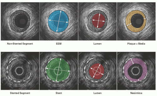 Figure 25.4 Quantitative IVUS measurements for non-stented (upper) and stented (lower) segments. Area measurements are performed with computer planimetry. External elastic membrane (EEM) area is defined as the area enclosed by the outermost interface between media and adventitia, while lumen area is determined by tracing the leading edge of the blood/intima border. Plaque + media area is calculated as the difference between EEM and lumen areas. Stent area is measured by tracing the leading edge of the stent struts, and neointimal area is calculated as the difference between stent and lumen areas. For EEM, lumen, and stent, the maximum (solid arrows) and minimum (dotted arrows) diameters are determined. For plaque + media and neointima, the maximum (solid arrows) and minimum (dotted arrows) thickness are measured. |
Qualitative Assessment
Plaque Characterization
In gray-scale IVUS, atheromatous plaques are classified into soft (echogenicity less than the surrounding adventitia), fibrous (intermediate echogenicity between those of soft plaques and highly echogenic calcified plaques), calcified (echogenicity higher than that of the adventitia with acoustic shadowing), and mixed plaques (more than one subtype contained within the plaque) (Figure 25.5). Calcium deposits are described qualitatively as superficial or deep according to the location of the leading edge of acoustic shadowing within the inner versus outer half of the plaque-plus-media thickness. The shadowing precludes determination of the thickness of a calcific deposit as well as visualization of vessel structures behind the calcium. Ultrasound reverberation (multiple ghost images of the leading calcium interface spaced at regular intervals radially) should not be misinterpreted as true vessel structures.
Since visual interpretation of conventional grayscale IVUS images has limitations in the precise detection and quantification of specific plaque components, several advanced signal analysis techniques have been developed and introduced into both research and clinical arenas. To date, three different systems have been commercialized based on computer-assisted analysis of raw radiofrequency (RF) signals in the reflected ultrasound beam: Virtual Histology™ IVUS, the iMap™ system, and the Integrated Backscatter system. The Virtual Histology™ (VH) IVUS system (Volcano Corp.) employs spectral radiofrequency analyses with a classification tree algorithm developed from ex vivo coronary datasets and classifies plaques as four types: fibrous, necrotic, calcific, and fibro-fatty. The iMap™ system (Boston Scientific Corp.) identifies and quantifies four different types of atherosclerotic components (fibrotic, necrotic, lipidic, and calcified tissues) based on the degree of spectral similarity between the backscattered signal and a
reference library of spectra from preserved histological data. Integrated Backscatter (IB) IVUS (YD Corp.) utilizes integrated backscatter values, calculated as the average power of the backscattered ultrasound signal from a sample tissue volume, to differentiate four tissue types: calcification, fibrosis, dense fibrosis, and lipid pool. All systems generate color-mapped images of the vessel wall, with a distinct color for each plaque component category (Figure 25.6). Current limitations of these techniques include limited spatial resolution for detection of thin fibrous caps; no classifications for thrombus, blood, or intimal hyperplasia; and potential errors in plaques with extensive calcification owing to limited ultrasound signal penetration.
reference library of spectra from preserved histological data. Integrated Backscatter (IB) IVUS (YD Corp.) utilizes integrated backscatter values, calculated as the average power of the backscattered ultrasound signal from a sample tissue volume, to differentiate four tissue types: calcification, fibrosis, dense fibrosis, and lipid pool. All systems generate color-mapped images of the vessel wall, with a distinct color for each plaque component category (Figure 25.6). Current limitations of these techniques include limited spatial resolution for detection of thin fibrous caps; no classifications for thrombus, blood, or intimal hyperplasia; and potential errors in plaques with extensive calcification owing to limited ultrasound signal penetration.
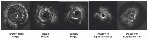 Figure 25.5 Plaque characterization by gray-scale IVUS. The brightness of the adventitia can be used as a gauge to discriminate between predominantly fatty and fibrous plaque (plaque that appears darker than the adventitia is considered fatty). Regions of calcification are strongly echo-reflective and create a dense shadow peripherally from the catheter, known as acoustic shadowing, with reverberation (arrow in the middle image). Large plaque burden with deep ultrasound signal attenuation despite absence of bright calcium and plaques with a large low-echoic region suggesting a lipid pool (arrow in the right image) are susceptible to distal emboli during balloon dilatation or stenting. |
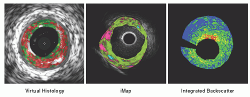 Figure 25.6 Examples of advanced plaque characterization by radiofrequency IVUS analysis. Virtual Histology™: Plaque components are determined using spectral radiofrequency signal analyses with a classification algorithm. Dark green = fibrous; light green = fibrofatty; white = calcium; red = necrotic core. iMap™: Classification of tissue is made based upon the degree of similarity between the sample and a reference frequency spectrum. This method enables confidence level assessment of each plaque component along with a color-mapped presentation superimposed on the corresponding grey-scale image. Green = fibrotic; yellow = lipidic; pink = necrotic; light blue = calcified. Integrated Backscatter IVUS: A colormapped presentation of integrated backscatter values (IB-IVUS). Blue = lipid pool; green = fibrous; yellow = dense fibrous; red = calcification. |
Abnormal Lesion Morphology
Thrombus
Thrombus is usually recognized as an intraluminal mass, often with a layered, lobulated, or pedunculated appearance (Figure 25.7). Acute thrombus may appear as a relatively echo-dense mass with speckling or scintillation, while old organized thrombus often has a darker ultrasound appearance. Thrombus is also more likely than soft plaque to have the appearance of blood flow in microchannels. However, none of these IVUS features is pathognomonic for thrombus, and slow blood flow, air bubbles, stagnant contrast, or an echolucent plaque should be considered as differential
diagnosis. Injection of contrast or saline may disperse the stagnant flow from the lumen, often allowing differentiation of stasis from thrombus.
diagnosis. Injection of contrast or saline may disperse the stagnant flow from the lumen, often allowing differentiation of stasis from thrombus.
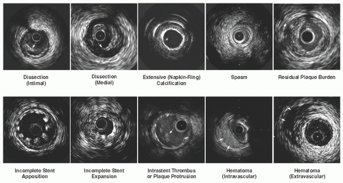 Figure 25.7 Common abnormal findings detected by IVUS. |
Dissection
Dissection appears as a fissure or separation within intima or plaque (Figure 25.7). The severity of a dissection can be quantified based on its depth (intimal, medial, or adventitial) and extent (circumferential or longitudinal). Intra-stent dissection is another type of dissection, characterized as separation of neointimal hyperplasia from stent struts.
Hematoma
Intramural (intravascular) hematoma is recognized as an accumulation of blood within the medial space, displacing the internal elastic membrane (IEM) inward and EEM outward (Figure 25.7). On the IVUS image, it is observed typically as a homogenous, hyperechoic, crescent-shaped area, but may present with a heterogeneous and/or layered appearance when contrast dye or saline is trapped in the false lumen. Entry and/or exit points may or may not be observed. Extramural (extravascular) hematoma is visualized outside the arterial wall in the adventitial tissue. It presents as irregularly shaped with an echo-dim pattern owing to the dilution of red blood cell concentration and dissemination throughout an echogenic adventitia. Extramural hematoma is more often realized after an interventional procedure, such as atherectomy or recanalization of CTO lesions, and requires careful attention in antithrombolytic and/or antiplatelet treatment.
Aneurysm
By IVUS, true aneurysm is defined as having an intact vessel wall and a maximum lumen area 50% larger than proximal reference. In contrast, pseudoaneurysm shows a loss of vessel wall integrity and damage to adventitia or perivascular tissue.
Vulnerable Plaque
Hypoechoic plaques without a well-formed fibrous cap are presumed to represent potentially vulnerable atherosclerotic lesions. Plaque rupture is diagnosed when a hypoechoic cavity within the plaque is connected with the lumen and a remnant of the ruptured fibrous cap is observed at the connecting site. Ruptured plaques are often eccentric, less calcified, large in plaque burden, positively remodeled, and associated with thrombus. In patients with acute coronary syndromes (ACS), multiple plaque ruptures are frequently detected by threevessel IVUS examination, suggesting that ACS are associated with pan-coronary destabilization. However, lumen compromise and clinical symptoms likely depend on the severity of the original or coexisting stenosis or on thrombus formation, not solely on plaque rupture.
Among the IVUS characteristics suggesting plaque instability, extensive positive remodeling represents the most consistent feature reported in gray-scale IVUS
studies. Pathological studies support this clinical IVUS finding by demonstrating that lesions with positive remodeling frequently exhibit large, soft, lipid-rich plaques with increased inflammatory cell infiltrate.7 Although current IVUS has limited spatial resolution for the detection of thin fibrous caps, a recent clinical study with synergy of IVUS and optical coherence tomography (OCT) has linked positive remodeling with thinning of the fibrous cap in serial coronary examinations.8 In another study utilizing VH-IVUS, a remodeling index was positively correlated with the presence and size of necrotic core, and inversely associated with fibrous tissue.9
studies. Pathological studies support this clinical IVUS finding by demonstrating that lesions with positive remodeling frequently exhibit large, soft, lipid-rich plaques with increased inflammatory cell infiltrate.7 Although current IVUS has limited spatial resolution for the detection of thin fibrous caps, a recent clinical study with synergy of IVUS and optical coherence tomography (OCT) has linked positive remodeling with thinning of the fibrous cap in serial coronary examinations.8 In another study utilizing VH-IVUS, a remodeling index was positively correlated with the presence and size of necrotic core, and inversely associated with fibrous tissue.9
There is increasing interest in the ability of IVUS to predict future coronary events. One of the largest natural history studies is the Providing Regional Observations to Study Predictors of Events in the Coronary Tree (PROSPECT) trial, which employed three-vessel imaging with VH-IVUS in 697 ACS patients.10 In this trial, a fibroatheroma (defined by VH-IVUS as the presence of >10% confluent necrotic core) was classified as a thin-cap fibroatheroma (TCFA) if >30° of the necrotic core abutted the lumen in three or more consecutive frames. Multivariate analysis identified three baseline IVUS characteristics that independently predicted events: (i) plaque burden >70% (hazard ratio [HR] = 5.03); (ii) VH-determined TCFA (HR = 3.35); and (iii) minimal luminal area <4.0 mm2 (HR = 3.21). Major adverse cardiac events (MACE) occurred in 18% of lesions that had all three of these characteristics and in <1% of lesions with none of them.
Interventional Applications
Angiographic Intermediate Lesions
A considerable number of angiographic intermediate lesions referred for elective percutaneous coronary intervention (PCI) are in fact hemodynamically insignificant and can be successfully managed with medical treatment alone. In early studies of proximal coronary lesions, minimum lumen area (MLA) measured by IVUS demonstrated reasonable correlation with results from physiologic assessment. The ischemic MLA threshold was identified as 3.0 to 4.0 mm2 for major epicardial coronary arteries based on physiologic assessment with coronary flow reserve, fractional flow reserve, or stress scintigraphy.11, 12, 13, 14 Patients with intermediate coronary lesions in whom PCI was deferred based on IVUS findings (MLA >4.0 mm2) had target lesion revascularization in only 2.8% with a composite event rate of 4.4%.15 More recent studies expanded the study population into a wide variety of lesions, and indicated that the diagnostic accuracies and the optimal cut-off values of the MLA can vary depending on the location or the amount of myocardium supplied by the target segment.16, 17, 18 Nevertheless, the consistently high negative predictive values of the MLA in these studies suggest that interventions can still be safely deferred at least in lesions with an MLA larger than the proposed cut-offs.
Calcified Lesions
It is important to identify calcified plaque since the presence, degree, and location of calcium within the target vessel can substantially affect the delivery and subsequent deployment of coronary stents. One important advantage of IVUS guidance is its ability to assess the extent and distance from the lumen of calcium deposits within a plaque. For example, lesions with extensive superficial calcium may require rotational atherectomy prior to stenting to avoid underexpansion. Conversely, lesions with deep calcium may be successfully treated by stenting alone, even with severe calcification seen on fluoroscopy, to achieve lumen expansion large enough for drug-eluting stents (DESs).
High-Risk Lesions for Distal Embolization
Evaluation of plaque composition by preinterventional IVUS may predict the occurrence of distal emboli during balloon dilatation or stenting that may result in the “slow-flow” or “no-reflow” phenomenon leading to periprocedural myocardial infarction. In gray-scale IVUS, predictive findings include large plaque burden with (non-calcium related) signal attenuation, a large low-echoic region suggesting a lipid pool, and thrombus-containing plaque19 (Figure 25.5). Recent studies with VH-IVUS or IB-IVUS have also demonstrated that the amount of lipid or necrotic core at preintervention was related to findings suggesting distal emboli.20, 21, 22, 23 Identification of high-risk plaques may help in selecting lesions suitable for distal protection devices.
Left Main Lesions
In the assessment of left main coronary disease, angulations, calcification, or spasm in this location can lead to poor catheter engagement and confound angiographic interpretation. Several studies have shown that high percentages of patients with angiographically normal left main coronary artery had disease when assessed by IVUS.24, 25, 26, 27 Conversely, only less than half of patients with angiographically ambiguous left main stenosis had a significant stenosis.28 This was especially true for ostial left main coronary disease where only 36% of the lesions had a significant stenosis and 41% had plaque burden <50% when assessed by IVUS. Plaque distribution in left main bifurcation lesions can also be evaluated more accurately with IVUS as compared with conventional angiographic classifications.29
The ischemic MLA threshold for the left main coronary artery is considered 6 mm2 based on physiologic assessment with fractional flow reserve30 as well as theoretical calculation using Murray’s law. This cut-off value has recently been validated in a prospective multicenter study (LITRO) where the predefined IVUS criterion of an MLA ≥6 mm2 was used for deferred revascularization in patients with intermediate left main disease.31 In a 2-year follow-up period, both cardiac death and event-free survivals were comparable between the deferred and the revascularized groups. Another study
has also shown the safety of IVUS-guided deferral of revascularization for intermediate left main disease, but using a larger MLA cut-off (7.5 mm2) predetermined based on the lower range of normal left main MLA from their clinical database.32 In practice, however, the judgment should be made in conjunction with other information, such as the presence of diabetes33 and plaque burden at the MLA site.34
has also shown the safety of IVUS-guided deferral of revascularization for intermediate left main disease, but using a larger MLA cut-off (7.5 mm2) predetermined based on the lower range of normal left main MLA from their clinical database.32 In practice, however, the judgment should be made in conjunction with other information, such as the presence of diabetes33 and plaque burden at the MLA site.34
Bifurcation Lesions
At bifurcation lesions, the extent of side-branch involvement can be difficult to assess by angiography alone. The combination of plaque and carina shift following balloon dilatation or stenting may cause severe narrowing or occlusion of a side branch, particularly in the presence of preexisting ostial disease.35 Such anatomical situations are responsible for the majority of creatine kinase elevations following stent implantation. Plaque deposition in the ostial lesion of a side branch can often be appreciated by looking across from the parent artery into the ostium of the branch, although accurate assessment requires direct imaging of the side branch. After PCI on bifurcation lesions using the two-stent technique, both inadequate postprocedural minimum stent area (MSA) and increased neointimal hyperplasia represent the major mechanisms of increased restenosis rate in the side-branch ostium.36
Chronic Total Occlusion Lesions
IVUS is useful in several aspects during intervention on CTO lesions. In lesions with abrupt-type occlusion, the entry point at the CTO ostium is often difficult to identify by angiography. If there is a side branch located near the entrance of the CTO, the IVUS catheter can be inserted into the side branch to examine the target for wire penetration.37 In addition, the IVUS catheter can possibly be inserted into the subintimal space to determine the direction of the true lumen. A true lumen is surrounded by all three layers of the vessel. Side branches may offer another clue since they should communicate with the true but not with the false lumen. It is important to note, however, that insertion of the IVUS catheter into the subintimal space has the potential risk of enlarging the subintimal space. Finally, as in the case of other PCI procedures, proper balloon and stent sizes as well as acute complications can accurately be evaluated by IVUS. Particularly, intramural or extramural hematoma (or perforation) can occur, not infrequently, during the CTO procedure. Early detection and precise assessment of these conditions are crucial for safe and effective treatment of patients with CTO.
Restenotic Lesions
The primary mechanism of restenosis can be accurately identified by IVUS, which significantly affects the treatment strategy in patients with restenotic lesions. An IVUS study of in-stent restenosis (ISR) lesions following bare metal stent (BMS) implantation demonstrated that 20% of lesions had an MSA of <5.0 mm2 and an additional 4.5% had other mechanical problems that contributed to restenosis.38 In another IVUS study of DES restenosis, 21% of lesions had an MSA of <5.0 mm2, 38% of which were not associated with significant neointimal hyperplasia.39 For this type of ISR, mechanical optimization is the first priority, and IVUS can differentiate mechanical issues from exaggerated neointimal proliferation that may truly require DES implantation within the original restenotic stent.
For DES treatment of ISR, early clinical studies suggested a hypothesis that full DES coverage of the original stent might be important for the prevention of recurrent restenosis. This aggressive optimization strategy, however, can be associated with several clinical issues, and thus, may not be feasible in every case. In a retrospective IVUS study of BMS restenosis treated with sirolimus-eluting stents, 77% of the uncovered BMS segments maintained adequate lumen patency at follow-up.40 Therefore, as long as the original BMS is well expanded and has a segment with sufficient lumen area, conservative coverage with DES can be a clinical option—the so-called “spot stenting” strategy. Another study from the TAXUS trials evaluated IVUS findings of patients who did not require revascularization at the time of 9-month angiography. At 3 years, revascularization was required in 4.9% of paclitaxel-eluting stents and 6.7% of BMS. Multivariate analysis identified MLA at 9 months as a significant predictor of later revascularization for both stent types.41
IVUS-Guided Selection of Device Size and Length
When assessed by IVUS, angiographically “normal” reference segments for PCI have 35% to 51% of plaque burden. Precise measurement of vessel size and lesion length by IVUS can guide the optimal sizing of devices to be employed. IVUSguided balloon sizing was first systematically pursued by the Clinical Outcomes with Ultrasound Trial (CLOUT),42 followed by a randomized multicenter study (Balloon Equivalent to Stent study: BEST) in which the nominal balloon size chosen was the closest size to the media-to-media diameter measured at the lesion site, and inflation pressure was determined based on the compliance curve to attain the target diameter.43 In a contemporary DES trial of complex lesions (Angiography versus IVUS Optimization: AVIO), the size of the postdilatation balloon was selected based on the average of the media-to-media diameters at multiple sites within the stented segment. The precise vessel size measurement is also critically important for size selection of self-expanding or fully biodegradable stents because undersizing of these devices is not amendable once deployed in the lesion.
Assessment of true lesion length by IVUS dictates the exact length of stent necessary to appropriately scaffold a lesion. Several IVUS studies of DES have identified higher reference plaque burden as an independent predictor of subsequent stent edge restenosis or thrombosis. The STLLR (The Impact of Stent Deployment Techniques on Clinical Outcomes of Patient
Treated with the CYPHER Stent) trial also demonstrated that geographic miss had a significant negative impact on both clinical efficacy and safety at 1 year following DES implantation.44 Therefore, complete coverage of the reference disease is currently recommended. Importantly, however, longer stent length has also been reported to be independently associated with DES restenosis and thrombosis.45,46 Online IVUS guidance can facilitate the determination of appropriate stent length for anchoring the stent ends in relatively plaque-free vessel segments while minimizing the stent length for complete lesion coverage. One practical approach has recently been proposed in a single-center registry, where stepwise IVUS criteria (plaque burden <50% as the primary target zone) determined the optimal landing zone for DES.47
Treated with the CYPHER Stent) trial also demonstrated that geographic miss had a significant negative impact on both clinical efficacy and safety at 1 year following DES implantation.44 Therefore, complete coverage of the reference disease is currently recommended. Importantly, however, longer stent length has also been reported to be independently associated with DES restenosis and thrombosis.45,46 Online IVUS guidance can facilitate the determination of appropriate stent length for anchoring the stent ends in relatively plaque-free vessel segments while minimizing the stent length for complete lesion coverage. One practical approach has recently been proposed in a single-center registry, where stepwise IVUS criteria (plaque burden <50% as the primary target zone) determined the optimal landing zone for DES.47
IVUS Guidance for Optimal Stent Expansion
The most consistent IVUS risk factor for DES restenosis and thrombosis is underexpansion of stent, the incidence of which has been reported as 60% to 80% of current DES failures. In the BMS era, the predicted risk of restenosis was reported to decrease 19% for every 1 mm2 increase in MSA.48 In the Can Routine Ultrasound Improve Stent Expansion (CRUISE) trial, IVUS guidance by operator preferences increased MSA, leading to a 44% relative reduction in target vessel revascularization at 9 months as compared with angiographic guidance.49 A subsequent randomized trial (Angiography Versus IVUS-Directed Stent Placement: AVID) also demonstrated larger acute dimensions achieved with IVUS-guided stent implantation that resulted in lower 12-month target lesion revascularization rates in complex lesion subsets.50
In the DES era, the relationship between postimplantation MSA and ISR can further be enhanced when variability of the biologic response (neointimal proliferation) is reduced. In the SIRIUS trial, a significant positive correlation was observed between baseline MSA and 8-month MLA with a stronger correlation with a higher regression coefficient in sirolimus-eluting stents than in control BMS.51 In another clinical IVUS study of sirolimus-eluting stents, the only independent predictors of angiographic restenosis were postprocedural final MSA of <5.5 mm2 and IVUS-measured stent length of >40 mm.45 In a series of restenotic BMS lesions treated with sirolimus-eluting stents, 82% of recurrent lesions had an MSA of <5.0 mm2 versus 26% of nonrecurrent lesions (P = 0.003).52 A pooled analysis of paclitaxeleluting stent trials has also identified baseline MSA as an independent predictor of subsequent in-stent restenosis in both paclitaxel-eluting stents and control BMS.53
In general, the relative benefit of further obtaining larger MSA to ensure a higher “safety margin” for an unexpected amount of neointima (the so-called bigger-is-better theory) can significantly vary among DES, depending on variability of subsequent neointimal proliferation.54 Given the wide variety of clinical backgrounds, patient risk factors, lesion morphologies, and disease complexities in clinical practice, one single pre-specified MSA endpoint could unlikely be effectively applied to all target lesions. Nevertheless, the ability of IVUS to assess the results of stent implantation more precisely than assessed by angiography significantly contributes to enhanced clinical judgment for individual patients. The utility of IVUS to ensure adequate stent expansion cannot be overemphasized, particularly if there are clinical risk factors for DES failure (e.g., diabetes, renal failure).
IVUS Assessment of Acute Stent Problems
Postinterventional IVUS can identify several stent deployment issues. Incomplete expansion occurs when a portion of the stent is inadequately expanded as compared with the distal and proximal reference dimensions, especially when dense fibrocalcific plaque is present (Figure 25.7). Incomplete stent apposition (or malapposition) occurs when part of the stent structure is not fully in contact with the vessel wall. After stent implantation, tears at the edge of the stent (marginal tears or pocket flaps) can occur, which may be recognized as haziness by angiography. The stent edge tears have been attributed to the shear forces created at the junction between the metal edge of the stent and the adjacent, more compliant, tissue, or to the effect of balloon expansion beyond the edge of the stent.
When investigated by IVUS, angiographic hazy lesions can represent a spectrum of anatomic morphologies, such as calcium, dissection, thrombus, hematoma, spasm, and excessive plaque burden with extreme remodeling at the reference segment (Figure 25.7). In addition to the diagnosis of the etiology, IVUS can also demonstrate the precise location and severity of these findings. For example, the location of the dissection can be important for risk of extension. Dissections on the free wall (same side as pericardium) may have a higher likelihood of propagating through to the vessel wall as compared with dissections on the mural wall, where the surrounding muscle constrains further propagation. Other criteria of vulnerable dissection are large, moving flaps and extensive medial tears occupying >50% of the vessel circumference (onion skin-like appearance). Identification of these patients at high risk of abrupt closure, who require preventive treatment such as additional stent implantation, is often possible and augments the angiographic findings.
IVUS Assessment of Chronic Stent Problems
Several IVUS studies have demonstrated that late-acquired incomplete stent apposition (LISA) is frequently observed in lesions of late DES thrombosis (Figure 25.8). A literature-based meta-analysis also suggested a significantly higher risk of late or very late DES thrombosis in patients with incomplete stent apposition at follow-up (OR 6.51, P = 0.02).55 The main mechanism of LISA after DES is often focal, positive vessel remodeling, whereas plaque regression or thrombus resolution is the predominant mechanism of LISA after BMS.56 In LISA with positive vessel remodeling, incompletely apposed struts are seen primarily in eccentric plaques, and gaps develop mainly
on the disease-free side of the vessel wall. Thus, the combination of mechanical vessel injury during stent implantation and biologic vessel injury with pharmacological agents or polymer in the setting of little underlying plaque may predispose the vessel wall to chronic, pathologic dilation. It remains controversial, however, whether this morphologic abnormality independently contributes to the occurrence of stent thrombosis.
on the disease-free side of the vessel wall. Thus, the combination of mechanical vessel injury during stent implantation and biologic vessel injury with pharmacological agents or polymer in the setting of little underlying plaque may predispose the vessel wall to chronic, pathologic dilation. It remains controversial, however, whether this morphologic abnormality independently contributes to the occurrence of stent thrombosis.
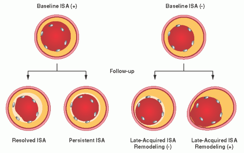 Figure 25.8 Classification of incomplete stent apposition (ISA). Baseline ISA can either be resolved (resolved ISA) or remain (persistent ISA) at follow-up. Late-acquired ISA without vessel expansion is typically seen in thrombus-containing lesions whereas late-acquired ISA with focal, positive vessel remodeling is more characteristic of brachytherapy and drug-eluting stents. |
Other IVUS-detected conditions that may be of importance in DES include non-uniform stent strut distribution and stent fractures after implantation. Theoretically, both abnormalities can reduce the local drug dose delivered to the arterial wall as well as affecting the mechanical scaffolding of the treated lesion segment. By IVUS, strut fracture is defined as longitudinal strut discontinuity and can be categorized based upon its morphological characteristics: (1) strut separation, (2) strut subluxation, or (3) strut intussusceptions.57 Another proposed classification focuses on potential mechanisms of the strut fracture, categorizing them based upon the presence and absence of aneurysm at the fracture site (Type I and II, respectively).58 Angiographic or IVUS studies have reported the incidence of DES fracture as 0.8% to 7.7%, wherein instent restenosis or stent thrombosis occurred in 22% to 88%. The exact incidence and clinical implications of strut fractures remain to be investigated in large clinical studies.
Long-Term Clinical Impact of IVUS-Guided Stent Implantation
In the BMS era, multiple studies have indicated the long-term benefits of IVUS in stent implantation, whereas controversial results were also reported in some IVUS-guided stent trials. This may be, in part, owing to inconsistent procedural endpoints for IVUS-guided stenting as well as various adjunctive treatment strategies that were used in these trials in response to suboptimal results. Overall, a meta-analysis of nine clinical studies (2,972 patients) demonstrated that IVUS-guided stenting significantly lowers 6-month angiographic restenosis (OR 0.75, P = 0.01) and target vessel revascularizations (OR 0.62, P = 0.00003), with a neutral effect on death and nonfatal myocardial infarction, as compared to an angiographic optimization.59
The impact of IVUS guidance during DES implantation on long-term clinical outcomes has also been assessed in several large studies. In a single-center study of IVUS-guided DES implantation versus propensity score matched control with angiographic guidance alone, a higher rate of definite stent thrombosis was seen in the angiography-guided group at both 30 days (0.5% versus 1.4%, P = 0.046) and 12 months (0.7 versus 2.0%, P = 0.014).60 In addition, a trend was seen in favor of IVUS guidance in 12-month target lesion revascularization (5.1% versus 7.2%, P = 0.07). Several other large registries have also demonstrated improved long-term clinical outcomes by IVUS-guided DES implantation in the treatment of unprotected left main (Revascularization for Unprotected Left Main Coronary Artery Stenosis: Comparison of Percutaneous Coronary Angioplasty versus Surgical Revascularization: MAIN-COMPARE)61 and bifurcation lesions.62 Finally, the real-world clinical impact of IVUS guidance for DES implantation in an unselected patient population has recently been investigated in the Comprehensive Assessment of Sirolimus-Eluting Stents in Complex
Lesions (MATRIX) registry,63 where IVUS guidance was associated with a reduction in both early and long-term (up to 2 years) clinical events, mostly driven by a reduction in the incidence of early myocardial infarction.
Lesions (MATRIX) registry,63 where IVUS guidance was associated with a reduction in both early and long-term (up to 2 years) clinical events, mostly driven by a reduction in the incidence of early myocardial infarction.
Safety and Limitations
During imaging, the most frequent acute complication is transient coronary spasm (up to 3%).64 Although major complications are rare (dissection, thrombosis, or abrupt closure in <0.5%), careful catheter manipulation is mandatory, similar to other interventional procedures. Regarding possible endothelial injury and disease progression as a chronic complication of intracoronary instrumentation, a study of transplant patients confirmed no acceleration of coronary artery disease associated with repeated IVUS examinations.65
When extensive calcification is present at the lesion site, it may be difficult to identify the exact size of the vessel owing to large acoustic shadowing. Severe calcifications can also hamper the delivery of the IVUS catheter, even if the stenosis is not severe. Similarly, severe angulation can affect the passage of the IVUS catheter, particularly with a shortmonorail configuration. With mechanical IVUS systems, severely angulated lesions may also cause significant image distortions that preclude accurate quantitative analysis. Offaxis position of the IVUS catheter may alter the vessel geometry on the IVUS image in an elliptical fashion.66 As a result, it may cause overestimation of the vessel dimensions, which requires careful attention, particularly for the evaluation of aorto-ostial segments.
Stay updated, free articles. Join our Telegram channel

Full access? Get Clinical Tree


