FIGURE 31.1. Mechanical and phased array transducers. Mechanical transducer images may have artifact related to the wire position.
(Courtesy of Boston Scientific Corporation, Natick, MA.)
Both types of transducers have limitations and generate artifacts that the user must be familiar with. Mechanical transducers typically have a wire channel that runs alongside the transducer that generates a wire artifact in the images (Fig. 31.2). In addition, mechanical transducers can trap small bubbles that result in air speckling if not flushed properly. Nonuniform rotational distortion (NURD) is a rotational distortion that occurs with mechanical transducers. This is typically seen in tortuous vessels, with kinking of guide catheters, or when hemostatic Tuohy-Borst valves are tightened excessively over the catheter. Excess stress on the IVUS catheter causes bending, and the rotational speed of the transducer varies, causing image acquisition to be distorted. Manufacturers of mechanical transducers have introduced corrective software to prevent this distortion. Phased array transducers can have ring-down artifacts. This represents an area immediately surrounding the catheter obscured by acoustic oscillations within the transducer. Adjustments in the gain of the transducer can be made once the catheter is outside of the sheath or guide catheter and not apposed to the arterial wall to minimize this artifact. Care must be taken to avoid adjusting too much, as true luminal signals can also be suppressed.4
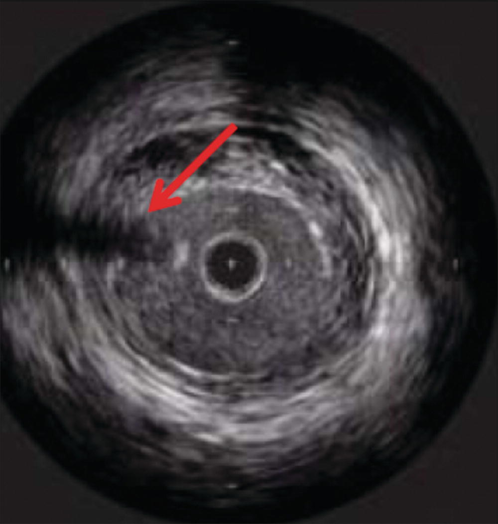
FIGURE 31.2. Wire artifact associated with mechanical IVUS transducers (red arrow).
IVUS catheters range in frequency from 8 to 50 MHz. As with all ultrasound probes, higher frequencies provide greater spatial resolution. The trade-off for using higher frequency probes is decreased depth of tissue penetration. Balancing these two factors is imperative when selecting the appropriate catheter for intravascular imaging. Catheters suitable for imaging the aorta and inferior vena cava (IVC) have a frequency range from 9 to 15 MHz. These catheters are typically able to image vessels with a maximum diameter of 5 to 6 cm, depending on the system. Optimal imaging of the iliac and common femoral arteries and veins can be obtained with catheters of 15 to 20 MHz. Smaller vessels, such as the superficial femoral, tibial, and renal arteries, are best imaged with transducers of 20 to 40 MHz (Table 31.1). Although vessel size may initially dictate the catheter used, other factors such as delivery system, sheath size, and wire access also factor into the selection of the appropriate catheter for the case at hand.
TABLE 31.1 Characteristics of Current Commercially Available Phased Array and Mechanical IVUS Catheters
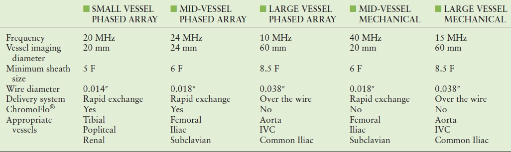
IVC, inferior vena cava.
Interpretation of IVUS imaging can be aided by two specific technologies: virtual histology and ChromaFlo®. Virtual histology is a computer-generated color map created from the reflected ultrasound signals. This map is displayed on the screen superimposed over the gray-scale image. Each of the four colors used represents a different component of plaque (Fig. 31.3). Deep green represents fibrous plaque, lighter green is fibro-fatty plaque, white represents dense calcium, and red is necrotic core. In an attempt to better understand the ability of virtual histology to characterize plaque, the Virtual Histology Intravascular Ultrasound Assessment of Carotid Artery Disease: The Carotid Artery Plaque Virtual Histology Evaluation (CAPITAL) study used virtual histology to assess carotid plaque prior to endarterectomy in 15 patients. Histologic composition of the plaques was compared to the virtual histology generated by IVUS. The authors found the diagnostic accuracy of virtual histology to range from 72.4% for calcified fibroatheroma to 99.4% for thin-cap fibroatheroma. The specificity ranged from 82% for intimal thickening to 100% for thin-cap fibroatheroma.
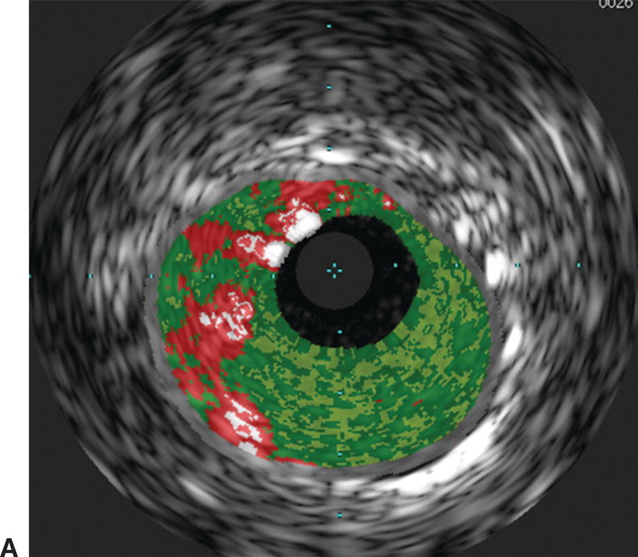
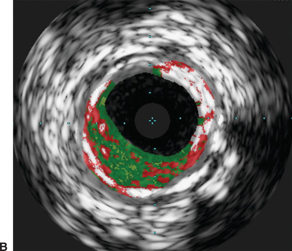
FIGURE 31.3. Virtual histology of peripheral plaque. A,Fibro-fatty plaque with small areas of necrotic core. B,Fibroatheroma with dense areas of calcification.
Small and mid-sized vessel phased array catheters are also able to offer color flow (ChromaFlo®) technology. When the location or patency of the vessel lumen is unclear, color flow imaging can be turned on to display the flow channel of the vessel (Fig. 31.4). Applications of this technology include evaluating the luminal irregularity of plaque and stent apposition. This technology has also been mounted on a reentry needle for use in sub-intimal angioplasty.
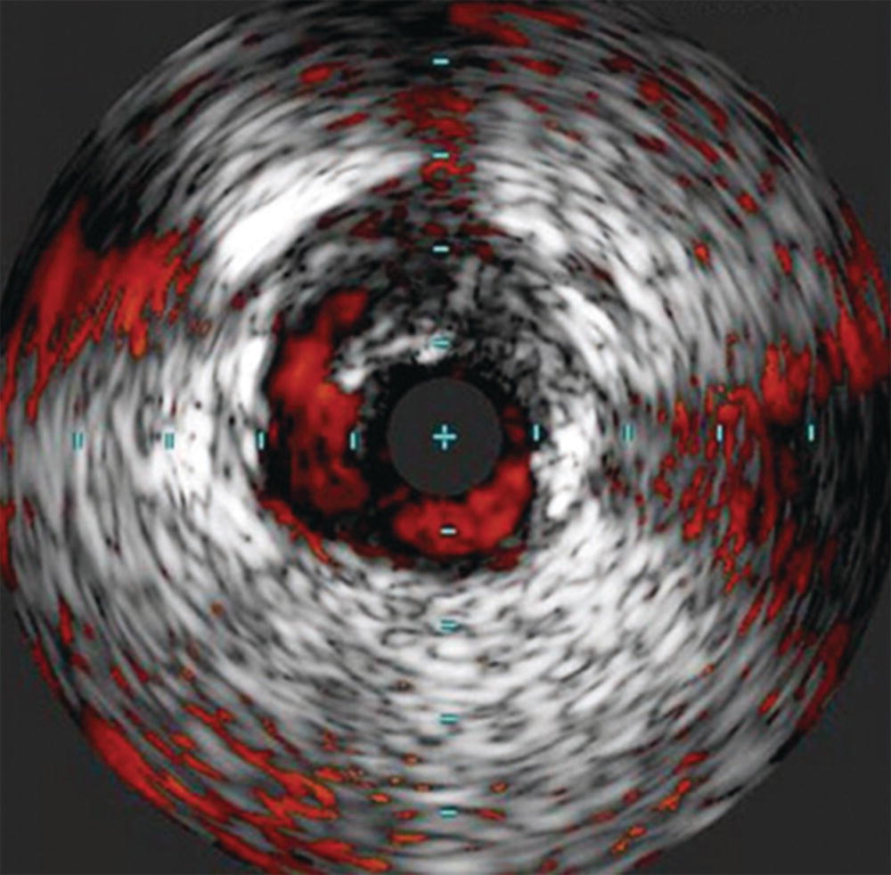
FIGURE 31.4. ChromaFlo® imaging showing delineation of an edge dissection after angioplasty.
(Images courtesy of Volcano Corporation, San Diego, CA.)
Applications
Venous
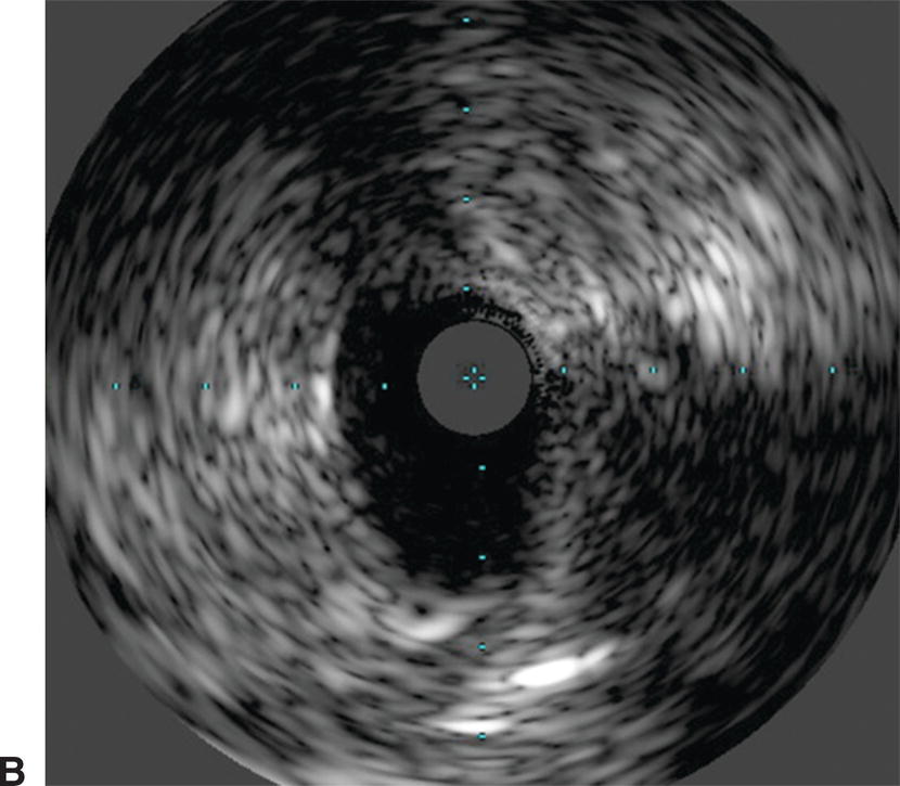
IVUS has emerged as an important adjunct for endovascular venous procedures. When used during thrombolytic procedures, IVUS can identify residual thrombus. Acute thrombus is difficult to visualize completely with IVUS images (Fig. 31.5). Chronic thrombus, on the other hand, is usually devoid of red blood cells and contains a higher concentration of fibrin, making it more echogenic and easier to distinguish from the vessel wall. Bands, frozen valves, spurs, or venous webs as the cause of thrombosis may not be easily identified with venography. IVUS can delineate irregularities that may be amenable to simple angioplasty and can determine if stent placement is required.
Use of IVUS has become essential in the treatment of iliac vein obstruction or stenosis resulting from arterial compression, also known as May-Thurner syndrome. Classic May-Thurner is caused by compression of the left common iliac vein by the right common iliac artery. Two additional areas of possible compression are located where the right external iliac artery crosses the right external iliac vein and where the left hypogastric artery crosses the left external iliac vein. Venography may show a flattening of the vein where compressed, and chronic compression can lead to scarring and thrombosis (Fig. 31.6). Venography can also severely underestimate the degree of venous stenosis, and stent sizing after recanalization without IVUS can lead to significant undersizing. Therefore, IVUS has become the preferred method for identifying the area of greatest venous narrowing to ensure accurate stent placement.
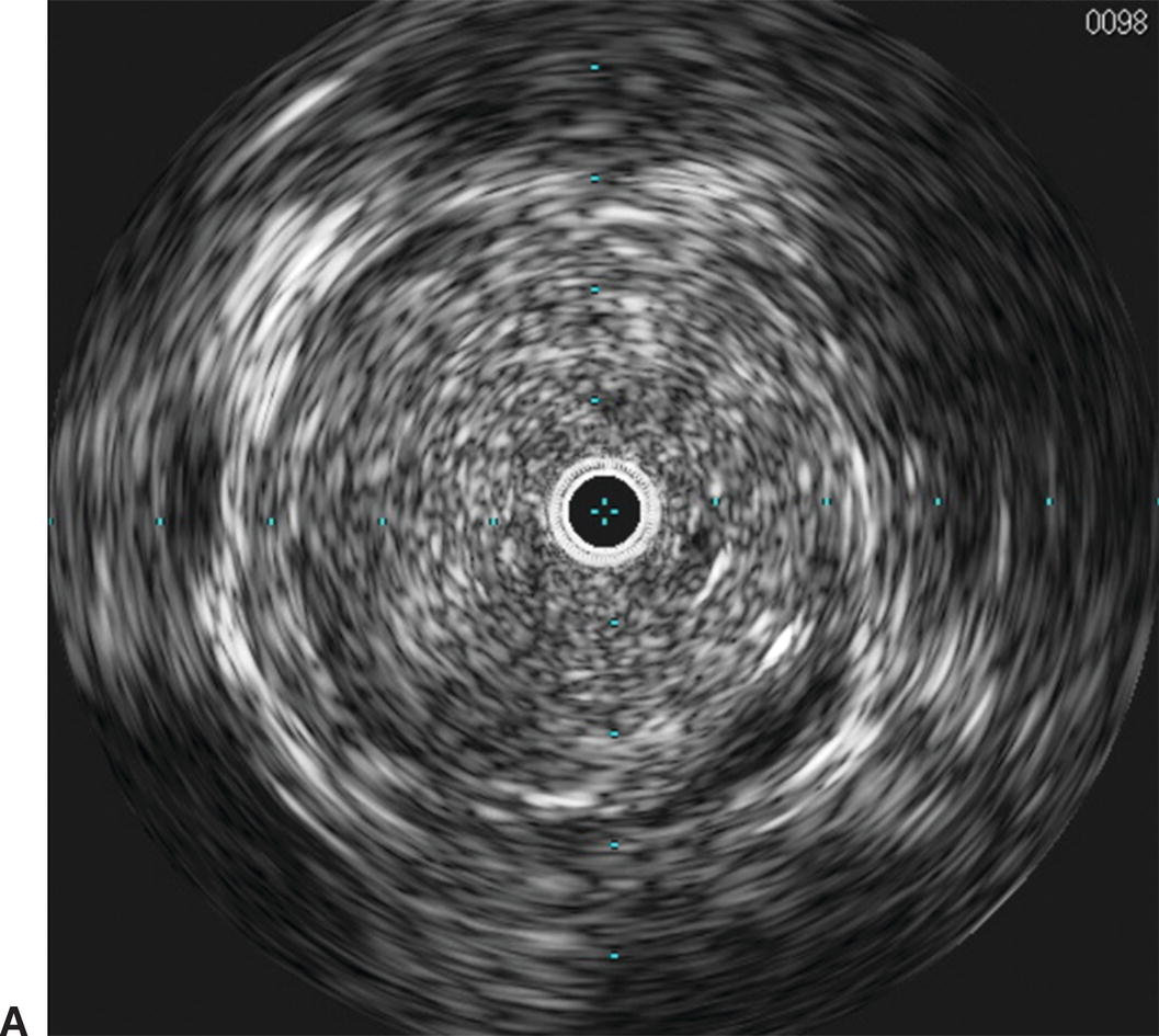
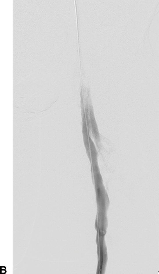
A,Intravascular ultrasound of acute thrombus filling the lumen of the external iliac vein. B,Venography demonstrating no flow of contrast through the external iliac vein due to acute deep venous thrombosis.
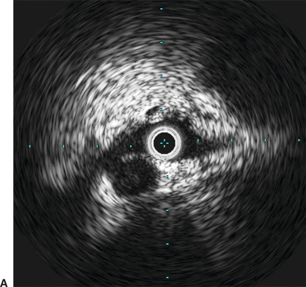
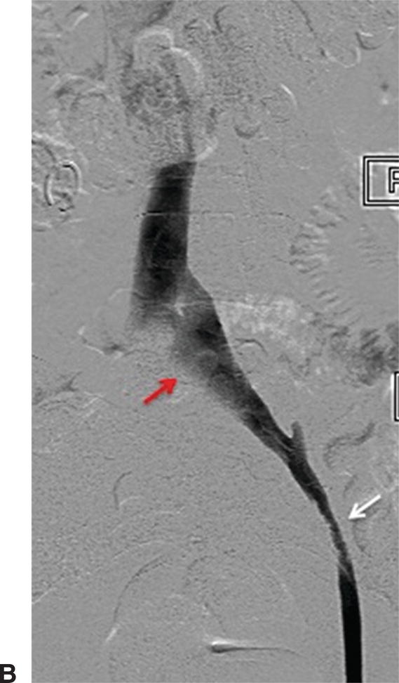
A,IVUS of the left common iliac vein compressed by the right common iliac artery. B,Venography showing the left common iliac vein flattened (red arrow). This is a classic sign for May-Thurner syndrome. Additionally, a residual chronic stenosis is seen in the external iliac vein (white arrow).
IVUS can be used for placement of IVC filters. This avoids radiation, iodinated contrast, and often transport of the patient from the intensive care unit. The standard approach for IVUS-guided IVC filter placement is from a femoral access site. The IVUS catheter is used to identify the left renal vein, which is anatomically lower than the right. Once the location of this vein is determined, the IVUS catheter is marked and removed so it can be used as a guide for the specific distance to insert the IVC filter for deployment. When transitioning to an IVUS-guided protocol for IVC filter placement, the general recommendation is to also use fluoroscopy for the first several procedures to ensure that the anatomy is clear and the filter placement is accurate.
Arterial
Peripheral Arterial
Identification of ostial renal artery lesions can be challenging. Patients with renal artery stenosis (RAS) may have impaired renal function, and efforts are made to avoid large volumes of nephrotoxic contrast. The renal arteries typically branch off in a downward direction from the lateral aspects of the aorta, but this can vary. With age, the aorta can also become tortuous, and the lateral locations of the renal artery origins become more posterior or anterior. This makes optimization of angiographic views of the renal artery ostia difficult (Fig. 31.7). When RAS is confirmed or suspected based on preoperative duplex ultrasound or an ACE-inhibitor–induced creatinine elevation, but it cannot be adequately imaged with angiography, IVUS can assist with delineation of lesion length and location. Used in conjunction with pressure measurements taken across renal artery lesions, IVUS has been shown to more accurately estimate the true degree of RAS and assist with selection of patients that may benefit from renal artery stenting.5
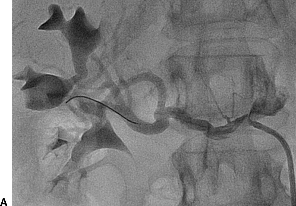
A,Renal angiography was unable to fully characterize this ostial right renal artery stenosis. B,IVUS and pressure gradient measurements showed a significant narrowing. After stent placement, the patient’s renal artery flow improved and the antihypertensive medical regimen was decreased.
Endovascular procedures have become first-line therapies for peripheral artery disease. Despite the evolution of these interventions, long-term patency rates vary widely depending on the arterial segment treated.6 Two-dimensional angiography can lead to inaccurate calculation of the true degree of arterial stenosis due to the inability to image the arterial wall. IVUS can visualize both the arterial wall and lumen, adding valuable insight on the nature and true severity of arterial narrowing. The ability to determine the exact vessel diameter allows for more precise selection of balloons and stents (Fig. 31.8). In a study of iliac artery interventions by Buckley et al, IVUS demonstrated that 40% of the stents placed were initially under-expanded. By addressing this problem at the initial procedure, the authors were able to show improved 3- and 6-year outcomes.7 Undersized stents cause early restenosis or lead to more limb-threatening thrombosis. The information provided by IVUS may help to avoid these complications and lead to improved outcomes for de novo peripheral arterial interventions.
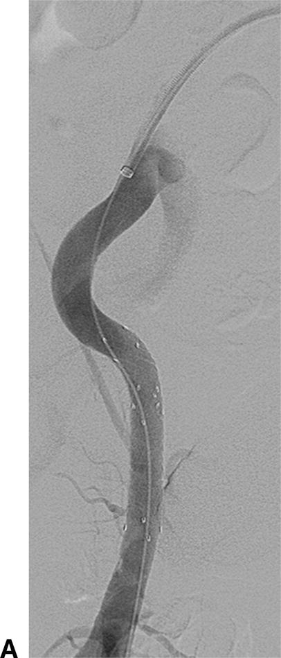
A,In this angiogram, the stent appears to be fully expanded and apposed to the arterial wall. B,Live IVUS imaging demonstrated that the stent was not apposed to the arterial wall during diastole.
For those patients who do develop restenosis, IVUS can aid in identification of the cause. Neointimal hyperplasia is generally recognized as the main cause of stent failure, although studies in the coronary and carotid literature have shown that negative arterial remodeling may also play a role in restenosis.8,9 The distinction between these two processes is essential to determine adequate treatment. Neointimal hyperplasia can reasonably be treated by endovascular means. Negative arterial remodeling may require consideration of alternative treatments such as bypass or interposition grafting.
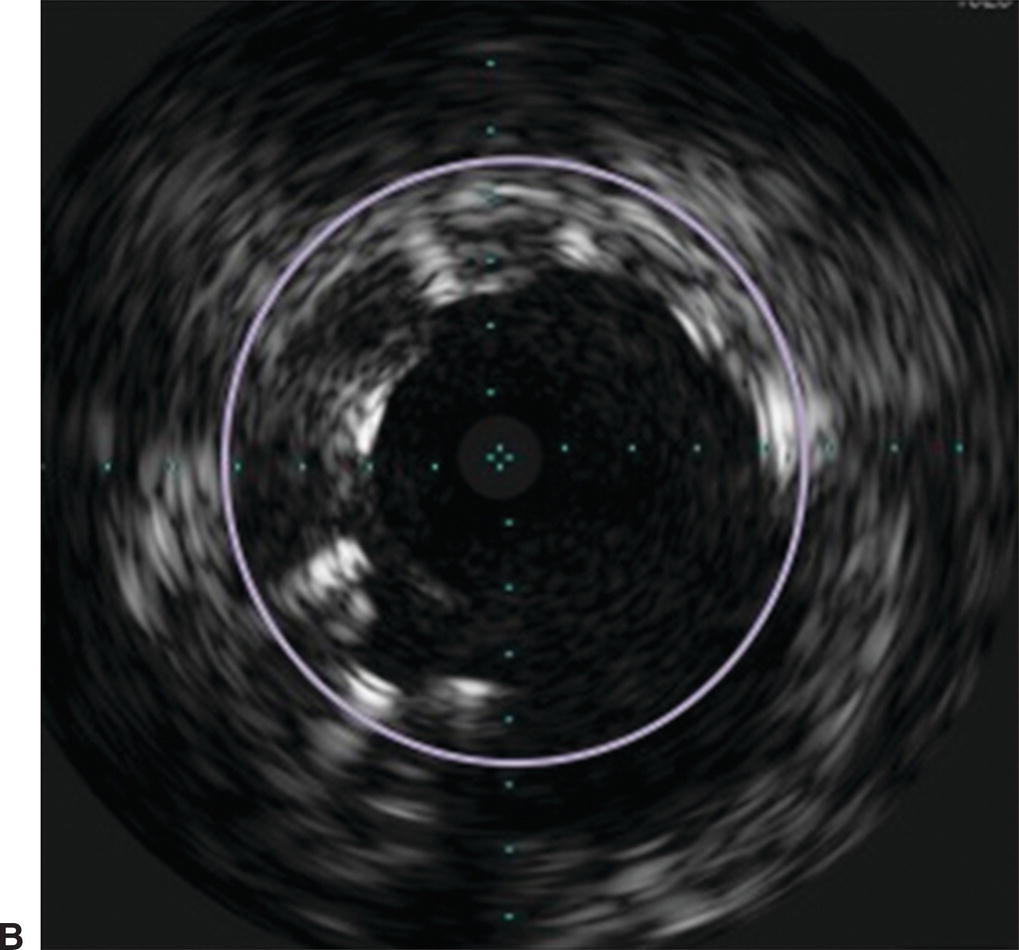
By combining IVUS with a reentry device, the Pioneer catheter (Medtronic, Minneapolis, MN) is a valuable tool for treating chronic total arterial occlusions. The catheter is dual lumen with a phased array transducer located near the tip. Just proximal to the transducer is a deployable reentry needle (Fig. 31.9). If wire maneuvers fail to reenter the true lumen during subintimal angioplasty, the catheter is advanced in the subintimal space. Color flow imaging can identify the true lumen of the vessel (Fig. 31.10). The true lumen is oriented at the 12 o’clock position and the reentry needle is deployed. A second wire is advanced into the true lumen, and the needle is withdrawn before the catheter is removed. The small reentry track can then be dilated to accommodate subsequent stent placement.
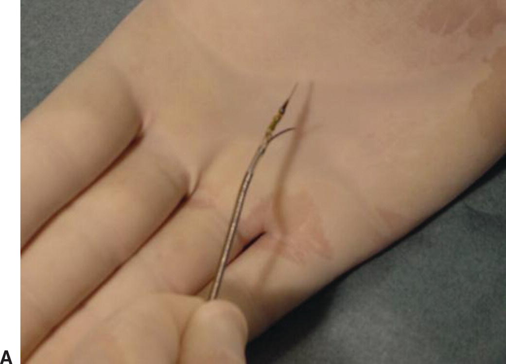
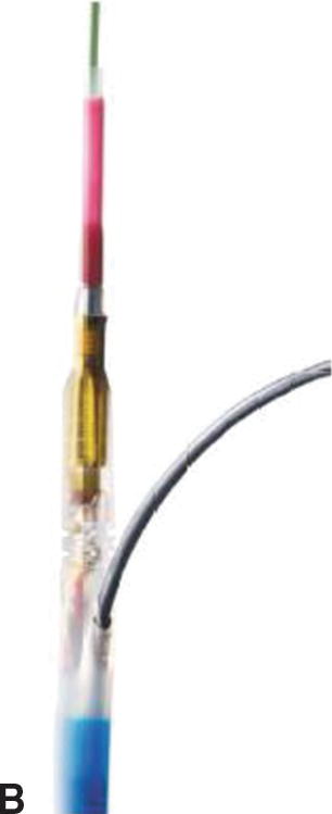
A,Pioneer catheter with entry needle deployed. B,Relationship of the reentry needle and IVUS probe.
(Images courtesy of Medtronic, Minneapolis, MN.)
Stay updated, free articles. Join our Telegram channel

Full access? Get Clinical Tree


