Fig. 3.1
TEE differentiation of degenerative MV disease: (a) Barlow’s disease with posterior leaflet prolapse (arrow): both leaflets are thick, bulky, and billowing (arrow); (b) Fibroelastic deficiency with P2 prolapse (arrow): both leaflets are thin and do not have billowing. A ruptured chord (arrow) is visible. AO aorta, LA left atrium, LV left ventricle, RA right atrium, RV right ventricle
TEE can provide anatomic information on patients with rheumatic valve disease [26]. Mitral stenosis (MS) is the most frequent complication of rheumatic valve disease [26]. Commissural fusion is an important feature to distinguish rheumatic from degenerative MS [25]. Commissural fusion can be assessed from the short-axis view of MV. Commissures are better visualized using real-time or live 3D TEE [29] (Fig. 3.2).
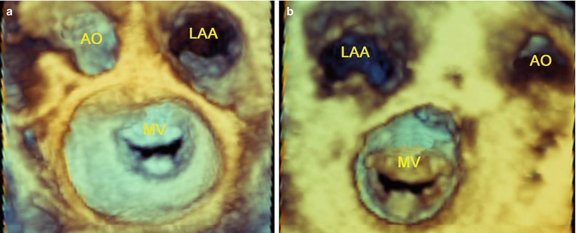
Fig. 3.2
Live 3D TEE shows commissures of the MV: (a) Commissures viewed from the left atrium; (b) Commissures viewed from the left ventricle. AO aorta, LAA left atrial appendage, MV mitral valve
Valvular Lesions
The valve lesions are critical data that a surgeon needs in order to define the best therapeutic strategy. In addition, the valve lesions may have great effect on the potential benefits of surgical intervention [27]. Any of the diseases previously mentioned can cause one or several lesions, which may affect one or several components of MV apparatus: the annulus, the leaflet, the chordae, the papillary muscles, and the ventricular wall.
TEE can accurately assess MV lesions in patients with degenerative MV disease [30]. The following definitions are used: leaflet prolapse is defined as “any portion of the MV that moved above the mitral annulus during systole” [30]; leaflet billowing as “excess leaflet tissue protrudes into the atrium during systole with the free edge of the leaflets remaining in apposition below the plane of the MV annulus” [31]; chordae elongation as “the free edge of the leaflet is above the annular plane” [32]; chordae rupture as “the presence of free and highly mobile, linear echoes is associated with flail mitral leaflet” [33] (Fig. 3.3); annular dilatation as “the ratio of annulus to anterior leaflet is greater than 1.3 or when the diameter of the annulus is greater than 35 mm” [34].
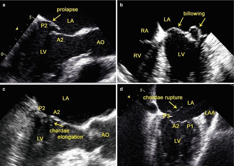
Fig. 3.3
TEE assessment of MV lesions: (a) leaflet prolapse; (b) leaflet billowing; (c) chordae elongation; (d) chordae rupture. AO aorta, LAA left atrial appendage, LA left atrium, LV left ventricle, RA right atrium, RV right ventricle
TEE can also accurately assess the valve and subvalvular apparatus in patients with MS due to rheumatic valve disease [26]. The pathological process of rheumatic MS causes commissural fusion, leaflet thickening and calcification, chordal fusion, or a combination of these processes [25]. Commissural fusion can be assessed from the short axis view of the MV; leaflet thickening from the mid esophageal long axis view; chordal fusion from the mid esophageal long-axis and four-chamber views. The typical rheumatic MS has a funnel shape and a small central orifice with a “fish mouth” configuration, which could be best visualized with live 3D TEE (Fig. 3.4).
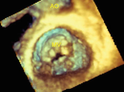
Fig. 3.4
Live 3D TEE shows the typical rheumatic MS: a “fish mouth” configuration
The Type of Dysfunction
Assessing the type of dysfunction in MV disease is important for the surgeon to identify the lesions causing the dysfunction [31]. In normal motion of the leaflet, MV regurgitation is due to either leaflet perforation or abnormal leaflet coaptation. MV prolapse may be due to either chordae rupture or elongation. Restricted leaflet motion is seen in rheumatic MV disease or ischemic cardiomopathy.
TEE is the principal diagnostic tool for the accurate evaluation of the dysfunction of the MV [23]. The “functional approach” of valvular disease is based on analysis of the motion of the leaflets by TEE and visual inspection during the operation [23]. Three functional types are described depending upon whether the motion of the leaflets is normal (type I), increased (typed II), or restricted (type III) (Fig. 3.5). Restricted leaflet motion may occur mainly during the opening of the valve (type IIIa) or during valve closure (type IIIb) [31]. Types I and II valve dysfunctions result in valve regurgitation whereas type III may result in valve regurgitation, stenosis, or both (Fig. 3.5).
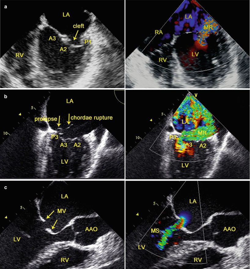
Fig. 3.5
TEE evaluation of the dysfunction of the MV (left) and hemodynamics (right): (a) type I; (b) type II; (c) type IIIa; AAO ascending aorta, LA left atrium, LV left ventricle, RA right atrium, RV right ventricle
3.2.1.2 Identification of the Precise Localization of Leaflet Dysfunction
The functional classification of MV disease is refined by the addition of the “Segmental Analysis” which allows precise localization of the leaflet dysfunction [23]. In segmental valve analysis, the valvular apparatus is separated into eight segments. The three scallops of the posterior leaflet are identified as P1 (anterior scallop), P2 (middle scallop), and P3 (posterior scallop). The three corresponding segments of the anterior leaflet are termed as: A1 (anterior part), A2 (middle part), and A3 (posterior part). The remaining two segments are the anterior commissure and the posterior commissure [23].
MV is examined with TEE by using four mid-esophageal views (the mid-esophageal four-chamber view, the commissural view, the two-chamber view, and the long-axis view) [35] and the transgastric basal short-axis view [36] (Fig. 3.6).
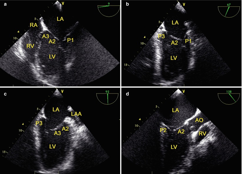
Fig. 3.6
The mid-esophageal mitral valve views: (a) the mid-esophageal four-chamber view; (b) the commissural view; (c) the two-chamber view; (d) the long-axis view. AO aorta, LAA left atrial appendage, LA left atrium, LV left ventricle, RA right atrium, RV right ventricle
The transgastric basal short-axis view is obtained at a multiplane angle of 0°–20° by anteflexing and withdrawing the probe at the level of the base of LV. The view provides the MV short axis view, with P3 being the closest to the apex of the sector [36].
The recent development of a fully sampled matrix-array TEE transducer (Philips Medical Systems, Andover, MA) allows excellent real-time imaging of MV in three dimensions [37] (Fig. 3.7).
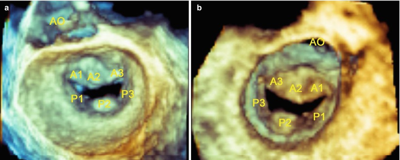
Fig. 3.7
Live 3D imaging of the en face view of the mitral valve from the left atrial perspective (a) and left ventricle perspective (b) at end-diastole. AO aorta
3.2.1.3 Evaluation of the Severity of the Hemodynamic Consequences
Assessing the severity of hemodynamic consequences is an important complement to functional valve analysis, and it is essential for clinical decision-making [24, 25].
The severity of MS is assessed according to published guidelines [25]. Routine evaluation of MS severity should combine measurements of mean gradient and MV area using planimetry and the T1/2 method. In case of discrepancy, the result of planimetry is the reference measurement, except with poor acoustic windows. MV stenosis is graded as being mild, moderate, and severe.
The severity of MV regurgitation is assessed according to published guidelines [24]. A comprehensive approach to the evaluation of the severity of MV regurgitation is required which integrates multiple parameters. Specific signs related to MV anatomy (regurgitant jet area, vena contracta width, flow convergence, pulmonary vein flow) along with supportive signs (pulmonary vein flow, peak mitral E velocity, and regurgitation jet profile) constitute the basic features of an integrated assessment. These specific signs include color flow jet area, mitral inflow, jet density, jet contour, pulmonary vein flow, and quantitative parameters regarding regurgitant volume, regurgitant fraction and effective regurgitant orifice area [24]. MV regurgitation is graded as being mild, moderate, and severe [24].
3.2.2 TEE-Guided Cannulation of Peripheral CPB
Conventional cardiac surgery has been performed via median sternotomy, which provides optimal access to all cardiac structures and the great vessels and allows central cannulation for CPB under direct vision. To perform robotic cardiac procedures through small port sites, peripheral vessel cannulation for CPB has been used. [6]. TEE may provide direct visualization of the target vessels, guidewire and cannulae [38]. TEE may be useful in guiding successful placement of the cannulae in the inferior vena cava (IVC), superior vena cava (SVC), and ascending aorta (AAO) in the establishment of peripheral CPB during robotic cardiac surgery [8].
3.2.2.1 TEE-Guided Cannulation of the Inferior Vena Cava (IVC)
The intrahepatic IVC view (70°–90°) and the mid-esophageal bicaval view (80°–110°) [36] are obtained in turn. A guidewire is inserted through a cutdown into the right femoral vein. Under TEE guidance, the guidewire is advanced into the IVC and then into the right atrium (RA) sequentially, and a femoral venous cannula (Medtronic, Inc, Minneapolis, MN, USA) is inserted over the guidewire with the distal end of the cannula parallel to the IVC wall and its distal tip positioned at or above the IVC/RA junction (Fig. 3.8). The guidewire is then removed.
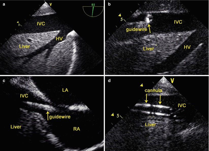
Fig. 3.8
TEE-Guided Cannulation of the Inferior Vena Cava: (a) the intrahepatic IVC view; (b) TEE shows the guidewire in the IVC; (c) TEE shows the guidewire in the RA; (d) TEE shows the cannula in the IVC. HV hepatic vein, IVC inferior vena cava, LA left atrium, LV left ventricle, RA right atrium
3.2.2.2 TEE-Guided Annulation of the Superior Vena Cava (SVC)
The mid esophageal bicaval view (80°–110°) is obtained [36]. Under TEE guidance, the guidewire is advanced into RA via the cannula in the right internal jugular vein and then the cannula is removed, and an arterial cannula (Medtronic, Inc, Minneapolis, MN, USA) is inserted over the guidewire with the distal end of the cannula parallel to the SVC wall and its distal tip positioned at or above the SVC/RA junction (Fig. 3.9). The guidewire is then removed.
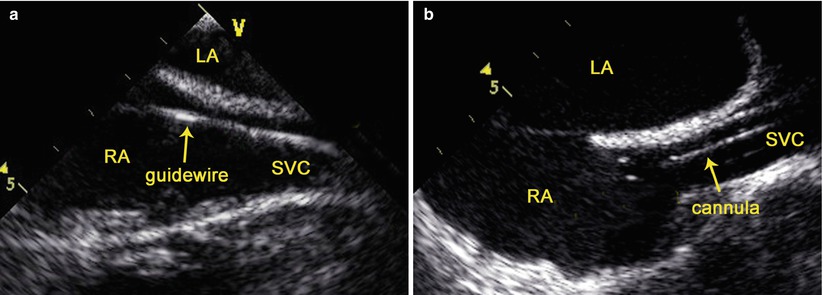
Fig. 3.9
TEE-guided cannulation of the superior vena cava: (a) TEE shows the guidewire in the SVC; (b) TEE shows the cannula in the SVC. LA left atrium, LV left ventricle, RA right atrium, SVC superior vena cava
3.2.2.3 TEE-Guided Cannulation of the Ascending Aorta (AAO)
The mid-esophageal aortic valve long-axis view (120°–160°) is obtained [36]. After cross clamping of the AAO, an angiocath (a cannula adapted for antegrade administration of cardioplegic solution) (Becton Dickinson Infusion Therapy Systems Inc., Sandy Utah) is inserted into the AAO via the fourth intercostal space, with its distal tip located in the aortic root under TEE guidance. Color flow imaging is used to indicate whether the angiocath is following the appropriate course (Fig. 3.10), and rapid flush of the cardioplegic solution is used to identify the tip of the angiocath (Fig. 3.10).
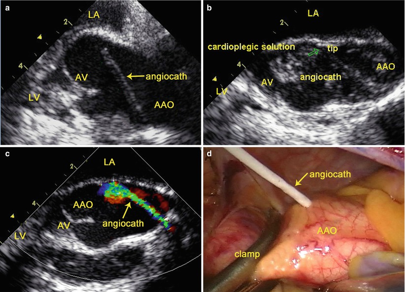
Fig. 3.10
TEE-guided cannulation of the ascending aorta: (a) TEE shows an angiocath inserted into the AAO; (b) Rapid flush of the cardioplegic solution identifies the tip of the angiocath; (c) Color flow imaging indicates the course of the angiocath; (d) Surgical view shows the angiocath inserted into the AAO. AAO ascending aorta, LA left atrium, LV left ventricle, AV aortic valve
3.2.3 TEE Examination After Pump-Off
3.2.3.1 Assessment of the Mitral Valve After Repair
Immediately after weaning from CPB, TEE is performed to assess the results of MV repair, and to assess for residual MV regurgitation, restriction of MV opening with stenosis, and systolic anterior motion of the leaflets of the MV.
Residual MV Regurgitation
Confirming the absence of significant residual MV regurgitation is the most critical aspect of postoperative valve analysis by TEE [35]. Immediate repair results by TEE are essential in determining whether reintervention is warranted. Residual MV regurgitation evaluated by TEE should be attempted as much as possible to create representative loading conditions with volume or vasopressors to fully assess the adequacy of the MV repair immediately after the patient is weaned from CPB, because insufficient preload and low ventricular pressure will result in underestimation of residual MV regurgitation [39, 40]. Appropriate volume loading, and hemodynamic manipulations are necessary to adequately evaluate the repaired MV.
The depth of coaptation should be documented and be at least 5 mm in a two-dimensional long-axis view to ensure adequacy of coaptation [39].
Mitral Stenosis (MS)
Acute MS following MV repair is a rare but severe complication, and it is more likely to be seen with the Alfieri edge-to-edge repair, commissuroplasty, and small annuloplasty ring [41, 42]. Intraoperative TEE can be utilized to diagnose iatrogenic MS immediately after MV repair. Continuous-wave Doppler gradients displaying a mean gradient greater than 7 mmHg or peak gradient greater than 17 mmHg is suggestive of clinically relevant MS after MV repair [41].
Systolic Anterior Motion (SAM)
SAM of MV leaflets causes obstruction of dynamic left ventricular outflow tract (LVOT) which is a known complication of MV repair that may necessitate immediate additional surgical intervention [43–45]. TEE may demonstrate a characteristic systolic anterior motion of the MV into the LVOT. Doppler echocardiography is used to determine the peak gradient. Peak gradient across the LVOT is increased from baseline as a result of dynamic LVOT obstruction. When SAM occurs after MV repair, hemodynamic maneuvers must be attempted before the results are declared inadequate. SAM can be resolved with volume loading, increased afterload, and withdrawal of inotropic agents [45].
Aortic Valve Leaflet Injury
The leaflets of the aortic valve may be inadvertently injured during percutaneous cannulation of the angiocath in the ascending aorta in the establishment of peripheral CPB. TEE can provide high-resolution images of the aortic valve and is helpful in determining the mechanism and cause of the injury immediately after CPB. Discontinuity in the leaflet of the aortic valve with an accentric jet of aortic regurgitation noted by TEE alerts the surgeon to perforated aortic valve (Fig. 3.11).
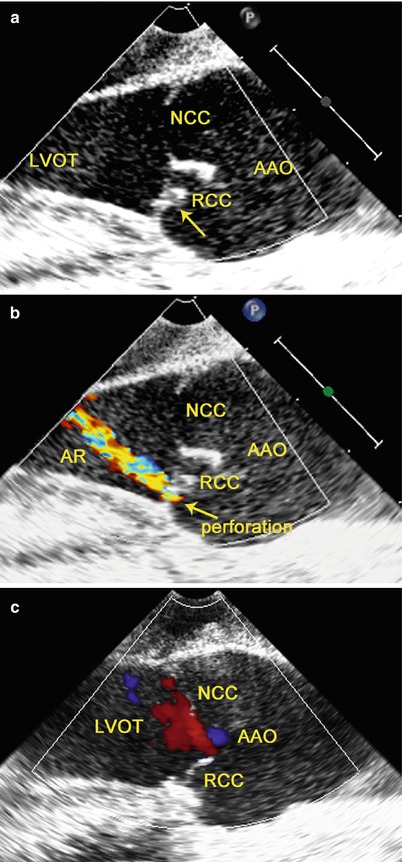
Fig. 3.11
TEE shows perforated aortic valve with regurgitation: (a) discontinuity is noted in the RCC (arrow); (b) an accentric jet of AR through this region on color flow imaging; (c) after repair of the RCC, there is no residual AR
3.2.3.2 Assessment of the Mitral Valve After Replacement
Immediately after MV replacement, TEE is performed to verify normal leaflet or motion of occluders and to detect technical problems such as paravalvular regurgitation and left ventricular outflow tract obstruction.
Confirmation of the Leaflet Motion
The opening and closure of the leaflets of the prosthetic valve in the MV position can be confirmed by TEE. Leaflet motion is best visualized using the 2D TEE mid-esophageal long-axis views and live 3D-TEE en face view of the MV. In 2D-TEE mid-esophageal long-axis views, the two mechanical leaflets are open, producing two parallel linear shadows within a circular annulus, and close symmetrically to a tilt angle of 85°–90° (Fig. 3.12). In the live-3D TEE en face view of MV, the leaflets motion of mechanical and bioprosthetic valves are better visualized (Fig. 3.13).
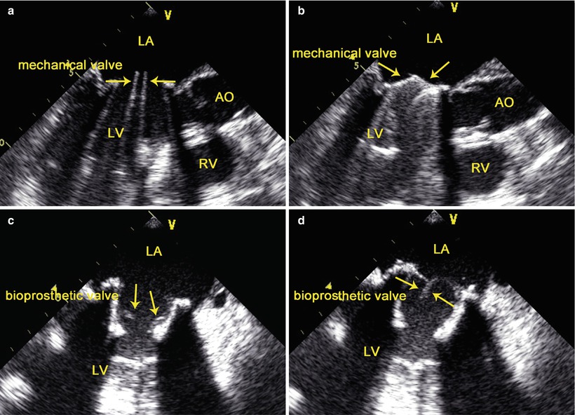
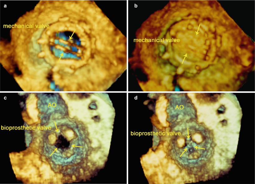
Fig. 3.12
Bileaflet mechanical valve (upper) and bioprosthetic valve (lower) in mitral position. TEE shows the opening (left) and closure (right) of the leaflets of the prosthetic valve (arrows). AO aorta, LA left atrium, LV left ventricle, RV right ventricle
Fig. 3.13
Bileaflet mechanical valve (upper) and bioprosthetic valve (lower) in mitral position. Live-3D TEE en face view of the MV from the left atrial perspective (upper) and from the left ventricle perspective (lower) shows the opening (left) and closing (right) of the leaflets of the prosthetic valve (arrows). AO aorta
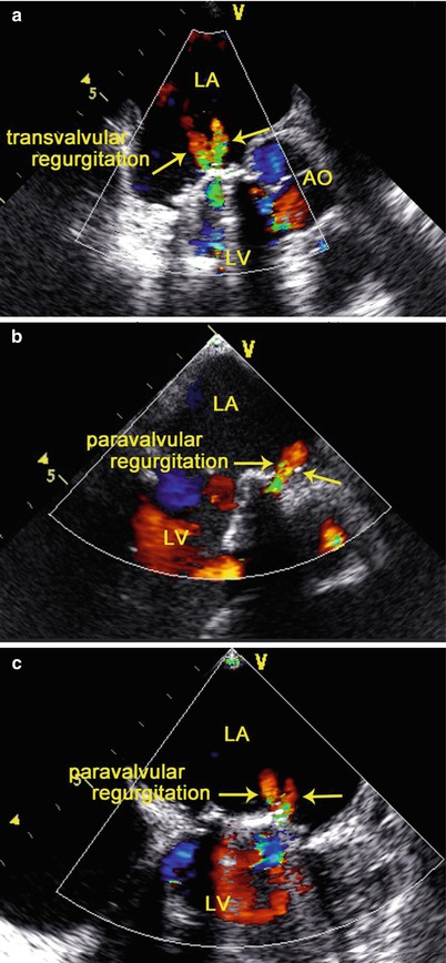
Confirmation of the Absence of Paravalvular Regurgitation
TEE demonstrates small characteristic regurgitant jets during leaflet closure. Closure backflow is the reversal of flow required for closure of the valve. In contrast, leakage backflow occurs after closure of mechanical valves and originates from the hinges and the regions of coaptation between the occluders and the valve ring. Physiologic regurgitation jets are small and short in duration. Mild transvalvular or paravalvular regurgitation can often be detected by TEE immediately after implantation. Small, insignificant transvalvular or paravalvular leaks are commonly observed immediately after CPB (Fig. 3.14), and should not be a cause for concern [46].