Transesophageal echocardiography (TEE) and intracardiac echocardiography (ICE) have revolutionized the ability to monitor and direct intraoperative surgical procedures and interventional cardiac catheterization procedures for patients with congenital heart disease. TEE has been the traditional imaging modality of choice for the past two decades in the operating suite and catheterization laboratory. More recently, the miniaturization of echocardiography technology has permitted ICE probes to be used in children and adults. Each imaging modality has advantages, disadvantages, and limitations, but the availability of both modalities has improved patient care in the operating suite and cardiac catheterization laboratory. Important limitations of TEE include the need for general anesthesia and potential problems related to airway management during prolonged use in the supine patient. Imaging limitations of TEE include some views of the posterior and inferior atrial septum that may be inadequate to exclude significant defects or shunts. The close proximity of the TEE probe to that area of the atrial septum creates this imaging issue. During atrial septal defect (ASD) device placement, with TEE there may be struggles with artifact when attempting to image through the device. In addition, the apical ventricular septum may be relatively inaccessible with TEE in some patients. For these reasons, the availability of high-quality intracardiac imaging has successfully merged the cardiac catheterization and echocardiography practices for patients with congenital heart disease.
INTRACARDIAC ECHOCARDIOGRAPHY
Equipment
Mechanical ICE systems were introduced in the 1980s. The current ICE system using an 8 or a 10 French (Fr) phased-array system was developed from single-array TEE prototype probes. The initial ICE probe was a 10 Fr catheter (AcuNav Diagnostic Ultrasound Catheter; Siemens Corporation, Mountain View, CA). This probe is a 64-element vector, phased-array transducer that is multifrequency (5.5 to 10 MHz) and mounted on a 3.3-mm (10 Fr) catheter with a maneuverable four-way tip (Fig. 35.1). The probe is capable of high-resolution two-dimensional and full Doppler imaging (pulsed-wave, continuous-wave, and tissue Doppler). The longitudinal plane provides a 90-degree sector image with tissue penetration of 2 to 12 cm. Currently, this probe is also available as an 8 Fr catheter. This catheter has similar echo capabilities but is longer than the 10 Fr catheter. The added length of the 8 Fr probe makes it more difficult to manipulate. The ICE catheter is advanced to the right atrium under fluoroscopic guidance. Image quality is optimized by adjusting gain, depth, frequency, and focal length controls. Complete ICE evaluation of both sides of the heart is then performed, sometimes with assistance of fluoroscopy to guide orientation and position of the ICE catheter.
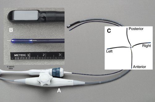
Figure 35.1. Intracardiac echo probe. A: Diagnostic ultrasound catheter (AcuNav) placed adjacent to a pediatric transesophageal echocardiography probe shows the relatively small size of the 10 Fr catheter. B: Close-up of the 3.3-mm-diameter catheter tip (arrows) shows the longitudinally oriented crystal array (palette). C: Overhead view of the four-way tip maneuverability of the diagnostic catheter.
Examination
The movements described in this chapter relate to the manipulation of the control mechanisms on the handle of the ICE catheter. Movement of the control handle to the left of midline results in movement of the catheter tip to the left as visualized from the front of the probe handle. However, these movements may not result in movement of the catheter tip in the same direction as illustrated outside of the body because, during an examination, the imaging palette is also being rotated in various directions to achieve a particular image plane. The imaging palette of the probe can be identified by the black stripe on the outside of the catheter and the black side of the probe evident on fluoroscopy. Thus, if the probe has been rotated to visualize a posterior structure (palette-directed posterior), posterior or rightward movement of the probe handle controls results in a more medial position of the catheter tip toward the atrial septum. When the catheter is angulated into unusual positions, such as the position required to achieve a short-axis image plane (anterior and leftward control movement), simple rotation of the catheter does not result in the longitudinal scanning effect as in TEE, but, rather, the tip of the probe moves in a large 360-degree arch. In practice, either the echo images can be followed and the probe manipulated to obtain the desired images, or the position of the probe tip can be monitored by fluoroscopy to obtain a standard probe position.
Image Acquisition
By advancing the ICE catheter from the inferior vena cava with the control mechanism in a free or neutral position, the catheter is placed in the mid right atrium, and a tricuspid valve inlet view is obtained by rotating the imaging palette of the catheter anteriorly and slightly leftward (Fig. 35.2). The catheter tip is then rotated clockwise to visualize the aorta and left ventricular outflow tract (Fig. 35.3). The lower atrial septum (cardiac crux) and mitral valve are then visualized by further clockwise catheter rotation (Fig. 35.4). In some cases, with some posterior control movement there is posterior deflection of the catheter tip, and a classic four-chamber view of the cardiac crux may be obtained as shown in Figure 35.4D. With continued clockwise rotation and cranial advancement of the catheter, a long-axis view of the atrial septum is obtained (Fig. 35.5).
In most cases, some leftward or anterior control movement with resultant lateral deflection of the catheter tip is needed to optimize this long-axis image by moving the transducer tip back and away from the atrial septum. With further cranial and caudal positioning of the catheter and slight counterclockwise and clockwise rotation, the entire atrial septum is evaluated with two-dimensional and color flow imaging. Usually, the lipomatous superior margin of the atrial septum (septum secundum) is clearly recognized, as is the membrane of the fossa ovalis (Fig. 35.6). From this same position, posterior, leftward imaging beyond the atrial septum allows visualization and evaluation of the left atrium and the left upper and lower pulmonary veins as they course in front of the descending thoracic aorta (see Fig. 35.5). The pulmonary veins are evaluated further by color flow imaging and pulsed-wave Doppler interrogation. Continued clockwise rotation then allows subsequent evaluation of the right lower pulmonary vein and subsequently the right upper pulmonary vein (Fig. 35.7), which is anterior and inferior to the right pulmonary artery. In some patients, visualization of the right pulmonary veins requires not only clockwise rotation but also some cranial advancement of the probe. With anterior flexion of the catheter tip by anterior and leftward control movement, the superior vena cava (SVC) is then evaluated (Fig. 35.8). The crista terminalis is often visible near the SVC.
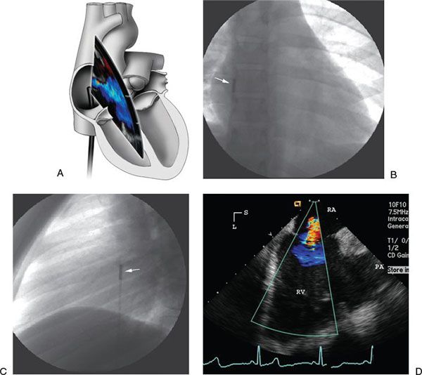
Figure 35.2. Tricuspid valve inflow view with ICE. A: Illustration of catheter course and probe position for right ventricular inflow view. B: Anteroposterior radiograph reveals the intracardiac echocardiography catheter tip in the right atrium (arrow) with the transducer palette pointed toward the tricuspid valve. C: Lateral radiograph shows the corresponding lateral image with the transducer tip (arrow) pointed anteriorly. D: Corresponding intracardiac echocardiography image of the tricuspid valve and right ventricle (RV) with mild tricuspid insufficiency shown with color flow imaging. L, left; PA, pulmonary artery; RA, right atrium; S, superior.
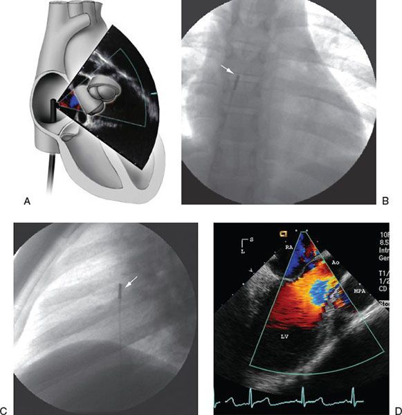
Figure 35.3. Evaluation of aorta and left ventricular outflow tract with ICE. A: Illustration of catheter course and probe position for view of the left ventricular outflow tract and aortic valve. B: Anteroposterior radiograph shows the intracardiac echocardiography catheter (arrow) now rotated slightly clockwise to point to the left ventricular (LV) outflow tract. C: Lateral image of the same catheter position (arrow). D: Corresponding intracardiac echocardiography image of the left ventricular outflow tract with color flow imaging. Ao, ascending aorta; L, left; MPA, main pulmonary artery; RA, right atrium; S, superior.
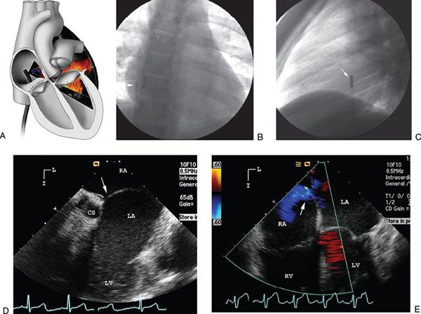
FIGURE 35.4. Evaluation of atrial septum and cardiac crux with ICE. A: Illustration of catheter course and probe position for view of the lower atrial septum and crux of the heart. B: Anteroposterior radiograph shows the intracardiac echocardiography catheter (arrow) further rotated clockwise to image the cardiac crux portion of the atrial septum above the mitral valve. C: Lateral image of this catheter position (arrow). D: Corresponding intracardiac echocardiography image of the cardiac crux (arrow) just above the mitral valve and coronary sinus (CS). E: Four-chamber view of the cardiac crux shows small right-to-left shunt across patent foramen ovale (arrow). I, inferior; L, left; LA, left atrium; LV, left ventricle; RA, right atrium; RV, right ventricle.
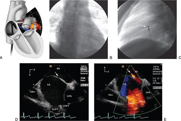
Figure 35.5. Long-axis view of atrial septum with ICE. A: Illustration of the catheter course and probe position for the long-axis view of the atrial septum. B: Anteroposterior radiograph of the intracardiac echocardiography catheter (arrow) after further clockwise rotation and slight anterior and lateral retroflexion of the catheter reveals a long-axis intracardiac echocardiography image of the atrial septum. C: Lateral image of the catheter position (arrow) shows the slight anterior flexion of the catheter. D: Corresponding intracardiac echocardiography image of the long axis of the atrial septum (arrow) thus obtained. E: Color flow image of left pulmonary venous return and a small left-to-right atrial shunt (arrow). A, anterior; DAo, descending aorta; LA, left atrium; LLPV, left lower pulmonary vein; LPA, left pulmonary artery; LUPV, left upper pulmonary vein; P, posterior; RA, right atrium; S, superior.
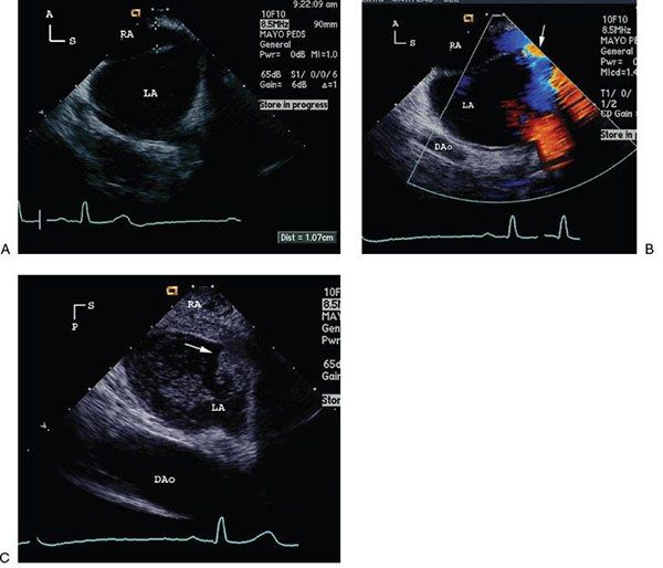
Figure 35.6. Evaluation of patent foramen ovale with ICE. A: Intracardiac echocardiography long-axis image reveals a large patent foramen ovale (PFO) (10 mm) in a 25-year-old patient with a previous stroke. B: Corresponding color flow image shows a large right-to-left shunt through the PFO (arrow). C: The same long-axis image of the PFO with a large resting right-to-left shunt (arrow) shown with an inferior vena caval agitated saline injection. A, anterior; DAo, descending aorta; LA, left atrium; P, posterior; RA, right atrium; S, superior.
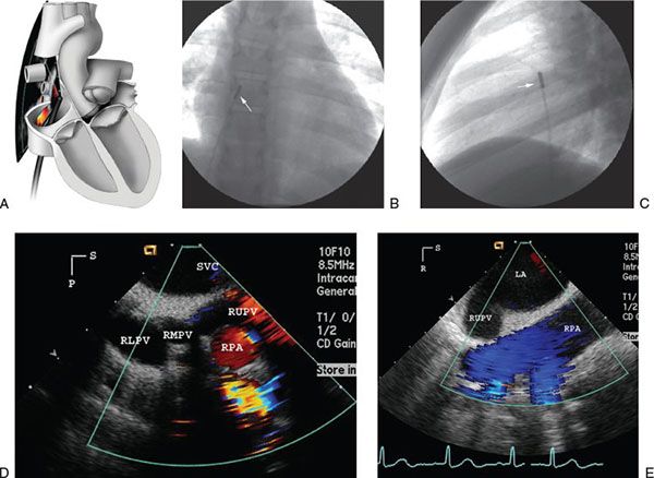
FIGURE 35.7. Evaluation of right pulmonary veins with ICE. A: Illustration of the catheter course and probe position for viewing the right pulmonary veins. B: Anteroposterior radiograph reveals intracardiac echocardiography catheter tip position (arrow) after further clockwise catheter rotation to the right to image the right pulmonary veins. C: Lateral radiograph shows catheter position (arrow). D: Corresponding intracardiac echocardiography image shows all three right pulmonary veins. Note that the right upper pulmonary vein (RUPV) courses anterior and then inferior to the right pulmonary artery (RPA). E: With the catheter tip moved across the atrial defect, the image then reveals a long-axis view of the RPA with the RUPV just inferior to the RPA. LA, left atrium; P, posterior; R, right; RLPV, right lower pulmonary vein; RMPV, right middle pulmonary vein; S, superior; SVC, superior vena cava.
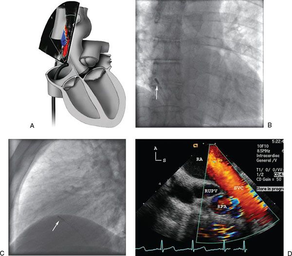
FIGURE 35.8. Evaluation of superior vena cava with ICE. A: Illustration of the catheter course and probe position to view the superior vena cava. B: Anteroposterior radiograph reveals anterior and lateral flexion of the catheter (arrow) to scan superiorly into the superior vena cava (SVC). C: Lateral image of the same catheter position (arrow) scanning superiorly. D: Corresponding intracardiac echocardiography image shows flow from the SVC into the right atrium (RA). The right upper pulmonary vein (RUPV) is noted as it courses anterior (A) and inferior to the right pulmonary artery (RPA). S, superior.
A short-axis image of the atrial septum and aortic root can be obtained with combined anterior and leftward control movement and with some clockwise rotation of the handle. This directs the tip anteriorly and medially toward and sometimes across the tricuspid valve annulus (Fig. 35.9). Short-axis images are important to access appropriate device positioning near the aortic root and provide a typical transverse image of the aortic valve and the atrial septum. The right lower pulmonary veins are visible near the back wall of the left atrium.
To cross the atrial septum, the catheter tip is repositioned in the mid right atrium and, with the imaging palette facing posterior to the atrial septum, is manipulated with posterior or rightward control movement to move the catheter tip toward the atrial septum. With the catheter tip seated adjacent to the atrial septum or, in many cases, across the interatrial defect, the pulmonary veins are again evaluated. Once across the septal defect, with further posterior and rightward control movement (catheter flexion), an en face mitral inflow view is obtained (Fig. 35.10). With the catheter across the atrial septum, in a neutral position and rotated anteriorly (counterclockwise), a detailed short-axis view of the aortic valve is obtained, and with slight clockwise rotation of the catheter, the right ventricular outflow tract and pulmonary valve are observed (Fig. 35.11). With posterior and rightward movement of the controls similar to the mitral valve view, the probe can be advanced into the left ventricle or near the lateral atrioventricular groove where scans of the ventricular septum, both atrioventricular (AV) valves, and the ventricles can be obtained similar in appearance to a four-chamber view (Fig. 35.12). This view provides excellent imaging of the inlet and membranous ventricular septum.
Returning to the right atrium, with combined anterior and leftward control movement similar to that to obtain a short-axis image, the curved probe can be manipulated across the tricuspid valve to visualize structures within the right ventricle. With advancement of the probe into the right ventricle, scans of the right ventricular outflow tract and pulmonary valve are easily obtained (Fig. 35.13). By releasing the curvature on the probe, it can then be rotated to scan inferiorly to obtain short-axis images of the left ventricle and the ventricular septum. These same views can be used to scan the membranous and muscular portions of the ventricle to visualize ventricular septal defects (VSDs) (Fig. 35.14).
Imaging Note: ALL ICE PROBE MANIPULATIONS WITHIN THE LEFT ATRIUM, LEFT VENTRICLE, AND RIGHT VENTRICLE SHOULD BE GRADUAL, GENTLE, AND PERFORMED WITH FLUOROSCOPIC GUIDANCE BECAUSE THE STIFF ICE PROBE MAY CAUSE DAMAGE TO THE VALVULAR APPARATUS AND OTHER STRUCTURES.
Three-dimensional ICE imaging is now commercially available with the Siemens SC2000 platform. The 3D ICE probe currently is only 11 French in size but also has the same functionality as the 2D catheter. The 4D images provide a real-time 20-degree 3D image. With similar catheter positioning as described with the 2D images, 3D images of the atrial septum, AV valves, and semilunar valves can be obtained (Fig. 35.15). A large recurrent ASD is better demonstrated with 3D ICE imaging as noted in Figure 35.16.
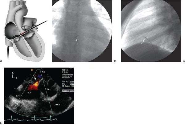
Figure 35.9. Short-axis view of atrial septum and aorta with ICE. A: Illustration of the catheter course and probe position for the short-axis view of the atrial septum and aorta. B: Anteroposterior radiograph shows retroflexion of the catheter tip by anterior and leftward movement of the probe controls and subsequent rotation of the catheter tip clockwise to place the tip (arrow) near or through the tricuspid valve. C: Lateral image reveals the catheter position (arrow) near the tricuspid valve. D: Corresponding intracardiac echocardiography image reveals a typical short-axis image of the heart at the level of the aortic valve. A small left-to-right shunt (arrow) is observed through the superior margin of the atrial septal defect. The main pulmonary artery (MPA) is also noted posterior to the aorta. A, anterior; Ao, ascending aorta; L, left; LA, left atrium; RA, right atrium.
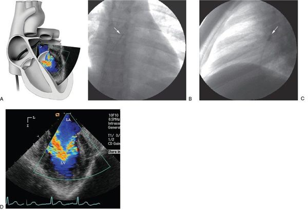
Figure 35.10. Evaluation of the mitral valve with ICE. A: Illustration of the catheter course and probe position for an en face view of the mitral valve from the left atrium. B: Anteroposterior radiograph shows the intracardiac echocardiography catheter (arrow) advanced across the atrial septal defect and flexed inferiorly to view the mitral valve orifice. C: Lateral radiograph reveals the same catheter position (arrow). Note the posterior location of the catheter in the left atrium. D: Corresponding intracardiac echocardiography image of the en face view of the mitral orifice. I, inferior; L, left; LA, left atrium; LV, left ventricle.
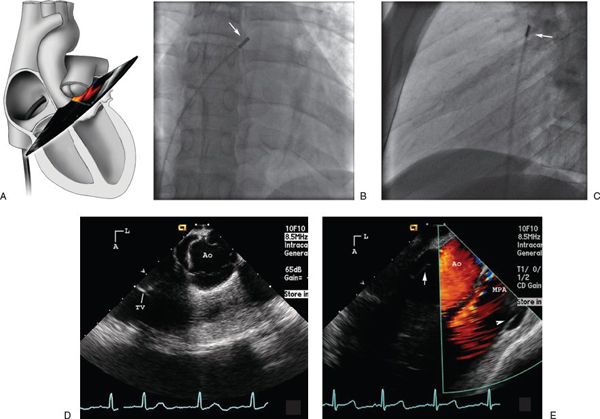
Figure 35.11. Evaluation of aorta, RVOT, and pulmonary artery with ICE. A: Illustration of the catheter course and probe position for a view of the aorta and pulmonary artery from the left atrium. B: Anteroposterior radiograph of the intracardiac echocardiography catheter tip (arrow) placed across the atrial septal defect into the left atrium but rotated counterclockwise to an anterior position immediately behind the aortic valve. C: Lateral image of the same catheter position (arrow). Note that the transducer is pointing anteriorly. D: Corresponding intracardiac echocardiography image shows in the short axis the fine detail of the aortic valve leaflets. E: With additional clockwise catheter rotation, a view of the right ventricular outflow tract and main pulmonary artery (MPA) is obtained. Arrow points to aortic valve and arrowhead points to pulmonary valve. A, anterior; Ao, ascending aorta; L, left; TV, tricuspid valve.
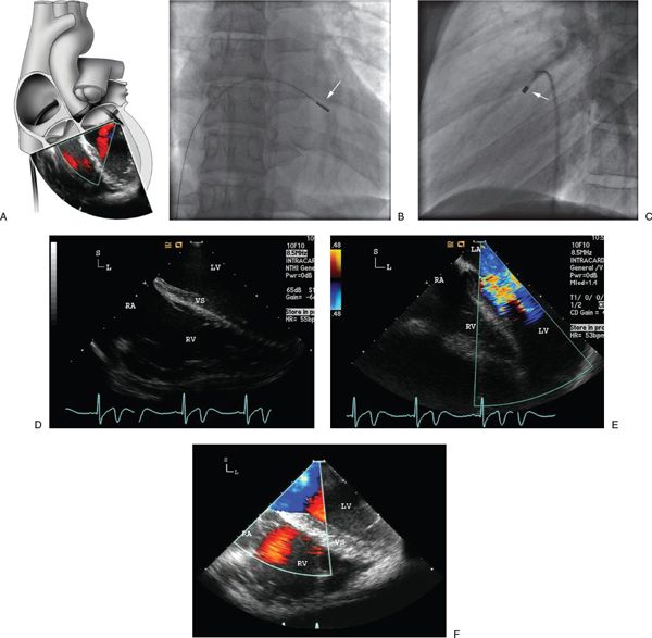
Figure 35.12. Evaluation of ventricular septum, atrioventricular valves, and ventricles with ICE. A: Illustration of the catheter course across the atrial septum and the probe position just inside the left ventricle near the left atrioventricular groove. Rightward and posterior control movement results in angulation of the probe to view the ventricular septum and both ventricles. S, superior; L, left; LV, left ventricle; RA, right atrium; VS, ventricular septum; RV, right ventricle. B: Anteroposterior radiograph of the intracardiac echocardiography catheter tip (arrow) at the left atrioventricular groove. C: Lateral radiograph demonstrating this catheter position. D: Corresponding intracardiac echocardiography image showing a four-chamber–like view of both ventricles and the ventricular septum. The membranous to inlet portion of the ventricular septum is well visualized. E: Color flow image showing mitral inflow. F: Similar view in another patient demonstrating a systolic image. LA, left atrium.
Applications
The potential applications of ICE to interventional cardiac catheterization continue to expand, not only with respect to catheter-based treatment of congenital and acquired heart disease but also to the management of cardiac arrhythmias. ICE imaging results in improved patient comfort compared with TEE. ICE imaging bypasses potentially poor acoustic windows that are commonly encountered during transthoracic echocardiography. In addition, the use of ICE imaging allows a “single operator” concept, thereby alleviating the need for an additional echocardiographer in the catheterization laboratory, provided the primary operator is familiar with ICE imaging and interpretation. The interventionalist has control of the echocardiographic ICE images and must be able to provide the appropriate image planes for diagnosis and catheter intervention. The ability to provide this imaging rapidly and without the need for other echocardiographic support expedites the procedure and shortens interventional procedure time.
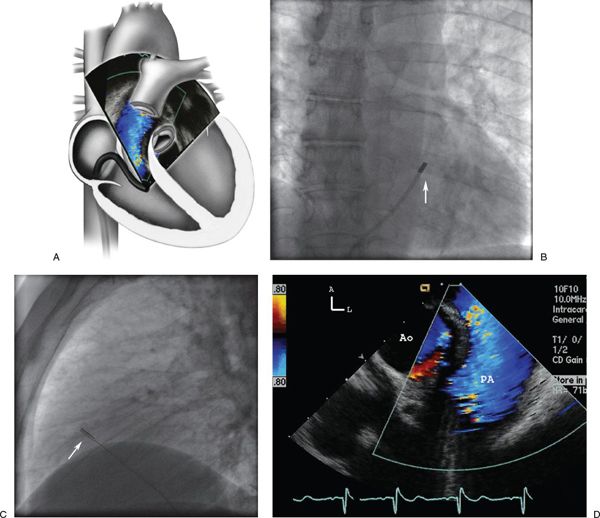
Figure 35.13. Evaluation of RVOT and pulmonary valve with ICE. A: Illustration of the catheter course and probe position across the tricuspid valve in the right ventricle. Because of the leftward and anterior control manipulation the probe is angulated to visualize the pulmonary outflow tract and valve superiorly. B: Anteroposterior radiograph of the intracardiac echocardiography catheter in the right ventricle. C: Lateral radiograph demonstrating the anterior catheter location. D: Corresponding intracardiac echocardiography image of the pulmonary outflow and color flow through the pulmonary valve. A, anterior; L, left; PA, pulmonary artery; Ao, ascending aorta.
Superior image quality and visualization of intracardiac structures allow accurate guidance of interventional procedures, thereby reducing both fluoroscopic and procedure times. Procedures where ICE imaging has been reported to be of benefit include, but are not limited to, guidance of transseptal puncture to gain access to the left atrium (Fig. 35.17), transcatheter closure device placement, radiofrequency ablation, cardiac biopsy, mitral valvuloplasty, and left atrial appendage occlusion.
Electrophysiology Procedures
Stay updated, free articles. Join our Telegram channel

Full access? Get Clinical Tree


