Fig. 12.1
Schematic diagram representing the various elements comprising a heart valve substitute system
12.3 Heart Valve Substitute Use Conditions
Understanding the environments and conditions under which the device is expected to function is critical for reliable operation and performance of a heart valve substitute. It is through a thorough understanding of the use conditions for a heart valve substitute that a robust product can be engineered. Figure 12.2 depicts typical exposure environments for a heart valve substitute over the course of the device life cycle. For the intent of this chapter, only the use conditions associated with device implantation and in vivo operation will be discussed in detail, but, as will be described within this chapter, there are aspects of device manufacturing and distribution/storage environments that are relevant for conditioning devices prior to in vitro testing.


Fig. 12.2
Exposure environments for heart valve substitutes during the device life cycle. The shaded box represents the aspects that will be covered in detail in this chapter
12.3.1 Device Implantation
Surgical heart valve substitutes (Fig. 12.3) are typically supplied within the device packaging preattached to a holder which serves to protect the device during shipment and implantation. Instruments are typically provided to facilitate transfer of the device from the sterile packaging to the sterile surgical field. The instruments are intended to securely hold the heart valve substitute while the surgeon places sutures through the sewing cuff and then facilitate “parachuting” the heart valve substitute down into the implant site. Prior to implantation, the implant site is surgically prepared to create an optimum landing zone for the valve; this may involve complete removal of the diseased native valve leaflets and debridement of calcium deposits that may interfere with the function of the heart valve substitute. During implantation, the heart valve substitute components may be manipulated to facilitate tying of sutures or to ensure no unintended interactions with adjacent anatomical structures. Following implantation of the heart valve substitute, the holder is removed, leaving the heart valve substitute securely affixed in position. After the device holder is removed, the functionality of the mechanical heart valve substitute is sometimes confirmed by ensuring valve leaflets fully open and close. During this valve and leaflet manipulation process, the heart valve substitute can be subjected to significant forces which may be well in excess of the anticipated loads during in vivo operation [15].


Fig. 12.3
Representative images of currently marketed surgical heart valve substitutes (left to right): stented porcine aortic valve, stented bovine pericardial valve, bileaflet mechanical valves, and stentless porcine valve
By design, transcatheter valves are delivered via small access sites and then tracked through potentially very tortuous vasculature to the target implant site. Necessarily, these devices must be compressed to a very small diameter, typically ranging from 18 to 24 Fr (6–8 mm) to facilitate loading the device on the delivery catheter or similar tool. Typically, smaller diameter catheters are required for transarterial delivery than for transapical delivery. Transcatheter valves are subjected to significant deformations during compression for loading onto the delivery tool which subjects the tissue, tissue attachment interface, and the device frame to potentially significant stresses/strains (Fig. 12.4).
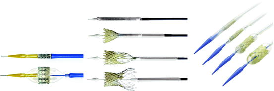

Fig. 12.4
Currently marketed transcatheter heart valve substitutes shown with associated delivery systems (left to right): bovine pericardial tissue aortic valve with balloon-expandable stainless steel frame, porcine pericardial tissue aortic valve with self-expanding Nitinol frame, and bovine jugular venous valve with balloon-expandable platinum-iridium frame
For almost all current transcatheter valve procedures, a balloon valvuloplasty is performed prior to valve implantation. This is accomplished by placing a balloon catheter across the diseased native valve and inflating the balloon. The balloon presses against the leaflets of the diseased native valve, which separates and stretches the valve opening, creating a more suitable landing zone for the replacement valve.
For valves utilizing balloon-expandable frames, the device is compressed onto the balloon catheter using a crimper, or it is crimped manually by the physician. This compression of the device results in plastic deformation of the frame, allowing the device to securely conform to the balloon catheter. The delivery system for balloon-expandable devices may or may not utilize a sheath to cover the valve since it is not required to constrain the device. Once the delivery system has been tracked to the anatomical valve location and the device is positioned within the desired implant location, the constraining sheath is retracted (if utilized) and the balloon catheter is inflated, expanding the heart valve substitute within the native diseased valve. The heart valve substitute is deployed to a diameter that is larger than the native annulus diameter in order to create an interference fit with the annulus and surrounding anatomy to firmly affix the device in place, thus maximizing valve orifice area and mitigating against both paravalvular leakage and device migration. During inflation of the balloon catheter to expand the device, rapid pacing is typically employed to decrease cardiac output and prevent large shifts in position of the heart valve substitute resulting from changes in chamber pressure when the valve orifice is occluded.
In the case of a valve with a self-expanding frame, the device may be compressed using a crimper or via loading funnels/cones. For self-expanding frames fabricated from super-elastic Nitinol, the crimping and loading process is typically conducted with the device immersed in a cold saline bath such that the frame material is in its low-temperature martensitic phase (see Sect. 12.5.1). This material phase makes the frame malleable and facilitates loading of the device onto the delivery system in a controllable manner. After mounting the device onto the delivery system, a sheath is placed over the device to constrain it so that it remains firmly attached and contained within the delivery system. Once the delivery system has been tracked to the anatomical location and the device is positioned in the desired implant location, the constraining sheath is retracted. At body temperature (37°C), the frame expands to its preformed configuration via the shape memory effect. The device expands until it apposes the valve annulus, creating an interference fit with the surrounding anatomy. As with balloon-expandable devices, the heart valve substitute size is selected such that the deployed diameter of the valve is larger than the native annulus diameter in order to create an interference fit with the annulus and surrounding anatomy. This sizing helps to firmly affix the device in place, maximizing valve orifice area and mitigating against both paravalvular leakage and device migration.
12.3.2 Device In Vivo Operation
After implantation within the target implant site, heart valve substitutes can be subjected to a combination of loading modes. These loading modes vary as a function of implant site (aortic, mitral, tricuspid, pulmonary), valvular disease etiology, and device design.
Since the primary function of the heart valve substitute is to control blood flow into and out of the heart, forces associated with pressure loading across the valve are one of the primary cyclic loading conditions to which a heart valve substitute is subjected. The differential pressure across the closed heart valve substitute under hypertensive blood pressure conditions represents the most significant pressure loading condition for the heart valve substitute components from a structural performance perspective. However, from a valve functional performance perspective, low cardiac output and hypotensive pressure conditions may represent a more challenging condition, i.e., the valve leaflets must open and close under low cardiac output and low-pressure conditions. The range of cardiac output and blood pressure conditions for hypotensive to hypertensive patient conditions to be considered when evaluating a heart valve substitute are listed in Table 12.1 based on the guidelines contained in ISO 5840 [3, 4].
Table 12.1
Heart valve substitute operational environment for right and left side of heart for the adult population [3, 4]
Parameter | Description |
|---|---|
Heart rate | 30–200 bpm |
Cardiac output | 3–15 Lpm |
Forward flow volume | 25–100 mL |
Patient blood pressure condition | Peak differential pressure across closed valve (mmHg) | |||
|---|---|---|---|---|
Pulmonary | Tricuspid | Aortic | Mitral | |
Hypotensive | 10 | 15 | 50 | 60 |
Normotensive | 19 | 27 | 100 | 120 |
Hypertensive | ||||
Mild | 28–34 | 40–49 | 115–129 | 140–159 |
Moderate | 35–42 | 50–59 | 130–144 | 160–179 |
Severe | 43–59 | 60–84 | 145–164 | 180–209 |
Very severe | ≥60 | ≥84 | ≥165 | ≥210 |
In addition to the pressure loading on the heart valve substitute, other loading conditions are imposed on the heart valve substitute as well. Since the perimeters of the native valve annuli are comprised of both ventricular myocardium and fibrous tissue, dynamic mechanical loading is applied to a device implanted within the valve annulus throughout the cardiac cycle. In addition, the motion of the heart within the chest cavity may subject the heart valve substitute to additional mechanical forces. The physiological loading conditions to which a heart valve substitute is subjected may include (1) radial dilatation and compression, (2) torsion, (3) bending, (4) axial tension and compression, and (5) linear/transverse compression (e.g., crushing) [4]. These combined cyclic loading conditions create a challenging fatigue environment for heart valve substitutes.
There is very limited quantitative information in the scientific literature regarding the potential magnitudes of the forces that may be generated within each of the four valve positions. For the aortic valve, no publications describing the forces generated by the aortic annulus and/or left ventricular outflow tract have been identified. Animal studies conducted with the healthy sheep model and using radio-opaque markers and sonomicrometry have described the dynamics of the aortic root in sheep [16, 17]. The objectives of both studies were to understand the deformation of the aortic root in relation to the cardiac cycle, not to quantify the potential forces that could be generated within the aortic root. For the mitral valve, there are limited publications that provide estimates of forces generated within the mitral annulus via animal models. Hasenkam et al. [18], Shandas et al. [19], and Jenson et al. [20] provide estimates of forces generated by the mitral annulus of healthy pigs and sheep. For the tricuspid valve, no publications describing the forces generated by the tricuspid annulus have been identified. For the pulmonary valve, no publications describing the force magnitudes generated by the pulmonary valve/right ventricular outflow tract have been identified, but there are publications that provide insight into potential loading modes for devices implanted within the pulmonary valve position [21, 22]. The pulmonary valve is the most anterior of the four heart valves, and as such it is the valve position in closest proximity to the chest wall. This creates the potential for a device implanted in this position to be subjected to cyclic compressive loading, as it is compressed between the anterior chest wall and the heart. As reported by Peng et al. [21], the substernal implant position was identified as an important risk factor for stainless steel stent fracture; nearly 90% of observed fractured stents in this study were implanted directly below the sternum.
Other considerations for both balloon-expandable and self-expanding devices include nonuniform deployment of the heart valve substitute, under- or over-deployment, and high or low deployment (with respect to intended implant position). These variations can potentially impact device performance and should be accounted for as part of the in vitro evaluation program.
A relatively new method being employed for identification and quantification of various loading modes and magnitudes to which an implanted device may be subjected is through the use of reconstructed multi-detector computed tomography (MDCT) data [23]. Obtaining MDCT data from patients implanted with a device of known mechanical characteristics and performing reconstructions of the deformed device throughout the cardiac cycle provides information that can be used to develop boundary condition estimates for that specific device within the target patient population. The deformation data obtained from the CT reconstructions can be used in conjunction with a finite element model of the implanted device to (1) predict the stress/strain distribution within the specific device under the measured boundary conditions or (2) estimate reaction force magnitudes that would result in the measured deformation of the specific device. The resolved reaction force estimates could then be used as boundary condition input for devices of other geometries intended for implantation in the same valve position.
Ultimately the device manufacturer must identify and justify the appropriate in vivo loading conditions for a heart valve substitute based on the device design in the context of the target implant site. In addition, consideration must be given to associated anatomic variability and pathological changes. Due to significant differences in anatomy, geometry, and cardiac dynamics for each of the four valve positions, loading information for one valve position (e.g., aortic) may not be directly applicable to another valve position (e.g., mitral).
12.4 Risk Assessment
Risk assessment plays a critical role in any device evaluation program. ISO 14971 [24] provides guidance and requirements for implementing a risk management program for a medical device. As described by ISO 14971, the risk assessment is comprised of risk analysis and risk evaluation. The risk analysis process begins by defining the intended use and operational environment for the device and by identifying the characteristics related to the safety of the heart valve substitute. Next, known and foreseeable hazards associated with the heart valve substitute system are identified, and an initial risk estimate for each hazardous situation is made.
The testing and analysis necessary to better estimate or refine the risk estimate associated with each hazard are then determined from information regarding the nature of the hazard and the corresponding failure modes/causes. This information provides input into the overall in vitro test strategy for the heart valve substitute. As such, the in vitro test and analysis requirements not only serve as a basis for verification and validation, but are also used to facilitate risk estimation for identified hazards through failure mode identification and/or failure probability quantification. The risk estimates for each identified hazard are then evaluated against the manufacturer’s established risk acceptance criteria to determine if associated risk levels are acceptable.
12.5 In Vitro Evaluations
The purpose of in vitro evaluations is to verify that the device meets the specified design requirements. The series of in vitro tests and analyses described herein provide quantitative and qualitative indications of the performance of the heart valve substitutes implanted via either surgical or transcatheter approaches.
In conducting these evaluations, it is important that the materials and valves to be tested are of the final design intended for clinical use and have been appropriately conditioned in a manner representative of the worst-case conditions that the device may encounter during use (e.g., maximum sterilization cycles, crimp diameter, crimp time, crimp cycles, deployed size/geometry, and in vivo deformations/loading conditions).
12.5.1 Material and Mechanical Property Testing
A fundamental input into the design of a device is an understanding of the physical properties of the materials to be used in its construction. This information determines the appropriateness of the proposed materials for use in the specific design. It is critical that the constituent materials of all components of the heart valve substitute system (e.g., frame, valve leaflets, and delivery system) be characterized as applicable to the specific design of the system.
There have been numerous material combinations utilized over the years in the design and manufacture of heart valve substitutes. Typical materials used in commercially released heart valve substitutes are summarized in Table 12.2; however, this table is not intended to be an exhaustive list.
Table 12.2
Typical materials used in commercially released heart valve substitutes
Surgical valves | Transcatheter valves | |||||
|---|---|---|---|---|---|---|
Sewing cuff | Leaflets | Frame/housing | Valve joining materials | Leaflets | Frame | Valve joining materials |
Polyester fabric | Pyrolytic carbon | Pyrolytic carbon | Polyester suture | Bovine pericardium | Nickel-titanium alloys | Polyester suture |
Bovine pericardium | Polymers | PTFE suture | Porcine pericardium | Stainless steel alloys | PTFE suture | |
Porcine aortic valve tissue | Titanium alloys | Nickel-titanium alloys | Bovine jugular | Platinum-iridium alloys | ||
Porcine pericardium | Cobalt-chromium alloys | Cobalt-chromium alloys | ||||
Equine pericardium | ||||||
It is important to characterize mechanical properties at various stages of manufacture, as applicable, for (a) the component raw materials, (b) the device components in their final manufactured state, and (c) the finished device after applicable exposure to simulated use conditions. The stress–strain response should be characterized under monotonic and cyclic load-unloading conditions to understand the cyclic response of the material. The generated mechanical property data provide material input information for use in finite element analyses (FEA) in order to determine in vivo induced stresses within the structural components.
The materials that comprise the main structural elements of currently marketed prosthetic heart valve substitutes typically consist of conventional metal alloys, pyrolytic carbon, various polymers, porcine or bovine heart tissue, and nickel-titanium alloys (e.g., super-elastic Nitinol). These materials exhibit a range of mechanical behavior, as is shown schematically in Fig. 12.5a for pyrolytic carbon, steel, and nickel-titanium and in Fig. 12.5b for polymers and tissue.
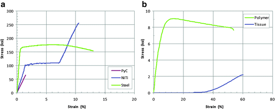

Fig. 12.5
Representative stress–strain response for pyrolytic carbon (PyC), nickel-titanium alloys (NiTi), and steel (a). Representative stress–strain response for polymer and valve tissue material (b)
Metallic alloys: Conventional metallic alloys are materials commonly used as structural elements of heart valve substitutes, and their mechanical (stress–strain) response is one of the most fundamental and well characterized. A typical stress–strain response is shown in Fig. 12.6. The initial response is characterized by an elastic region in which the stress is proportional to the strain. Beyond a certain limit, defined as the yield point, permanent (plastic) deformation occurs, which is not recoverable upon unloading. Continued loading will ultimately result in failure. The following is a list of typical mechanical properties that characterize conventional metal alloys: (1) elastic modulus (E), (2) yield strength (YS), (3) ultimate tensile strength, (4) elongation at failure (ε f), and (5) Poisson’s ratio.
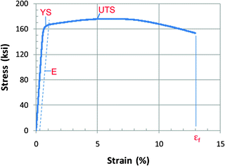

Fig. 12.6
Representative stress–strain response for engineering alloy with relevant parameters noted. ε f elongation at failure; E elastic modulus; UTS ultimate tensile strength; YS yield strength
Pyrolytic carbon: Pyrolytic carbon has been used successfully for decades in mechanical heart valve substitutes due to its good biocompatibility, thromboresistance, and durability [25]. Like ceramics, the mechanical behavior of pyrolytic carbon is linear elastic and exhibits no appreciable plastic deformation (Fig. 12.5a), exhibiting high strength and better ductility than most ceramics. However, due to the lack of plastic deformation, the material is relatively brittle and very sensitive to defects. As such, measures of strength are typically performed on a statistical basis on samples that are prepared to be representative of manufacturing processes specifically designed to remove surface defects.
Polymers: Surgical tissue valve frames are commonly fabricated from polymeric materials. Although their mechanical stress–strain behavior may appear similar to metals (Fig. 12.5), polymers are not as strong but can withstand far more deformation than most metals. Being viscoelastic, these materials will creep or continue to deform under constant load and will relax under constant deformation [26]. As such, their response is very sensitive to the loading rate, and their characterization should consider rates that will be experienced in vivo.
Bovine, porcine, and equine heart tissue: Bovine, porcine, and equine pericardium and porcine aortic valve tissues are used to construct leaflets in heart valve substitutes. In addition, some heart valve substitutes are comprised of a bovine jugular vein and valve. All animal tissues are subjected to various fixation processes, which are typically glutaraldehyde-based, to preserve and retain durability of the tissue during in vivo operation. Due to the oriented fibril nature of the collagen, tissue behavior is typically anisotropic (Fig. 12.7) and is often characterized under biaxial loadings [27]. These tissues can undergo extensive deformation (∼100–200%) with minimal force before ultimately stiffening and rupturing. Further, given their high water content, they exhibit incompressible, viscoelastic behavior.
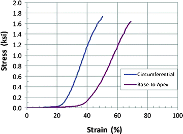

Fig. 12.7
Stress–strain diagram depicting typical glutaraldehyde-treated bovine pericardium tensile behavior in the circumferential and radial directions
Nickel-titanium alloys: Some metals, such as Nitinol (an alloy of approximately equiatomic nickel and titanium content), when combined and processed in specific ways exhibit unique mechanical behavior that is particularly suited for medical devices. An example of a Nitinol stress–strain curve, depicting its unique behavior, is shown in Fig. 12.8. Unlike conventional metals that exhibit permanent (plastic) deformation after about 0.5% deformation, Nitinol is capable of deformations up to 8% without permanent set. This “super-elastic” behavior makes Nitinol particularly attractive for vascular stents and transcatheter valves. The super-elastic behavior is the result of a microstructural shape change that occurs when the stress level is sufficient to cause the initial austenitic phase to transform to martensite during the upper plateau. Unloading before approximately 8% strain causes a reverse transformation from martensite back to austenite at the lower plateau stress and full recovery can be achieved. Continued loading beyond 8% strain results in plastic behavior typical of traditional metals.
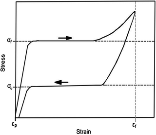

Fig. 12.8
Typical stress–strain curve for super-elastic Nitinol depicting “flag-shaped” hysteresis curve. The upper plateau σ f is measured as the inflection point during loading; the lower plateau σ u is measured as the inflection point during unloading; ε f is the total deformation strain; ε p is the permanent set [28]
Nitinol frames possess unique metallurgical and mechanical properties that facilitate (1) the loading of the device onto the delivery system, (2) the transcatheter delivery and implantation procedure, and (3) the mechanical performance of the valve postimplantation. When processed appropriately, Nitinol exhibits a shape memory effect. This effect describes the ability of a frame made out of a shape memory alloy like Nitinol to revert to its original shape and configuration upon heating after being severely deformed at a sufficiently low temperature. With slightly different processing, a shape memory alloy can also exhibit super-elasticity. In the super-elastic condition, a frame can undergo large mechanical deformations and instantly revert to its original configuration upon unloading at a single temperature. Both the shape memory effect and the super-elastic behavior are the result of reversible martensite phase transformations. The phase transformation stimuli might be a change in temperature (shape memory effect) for example, or the application of a mechanical stress (super-elasticity). Figure 12.9 describes typical properties used to characterize the mechanical properties of super-elastic Nitinol alloys for input into computational analyses.
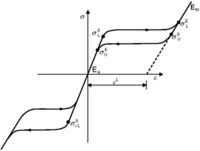

Fig. 12.9
Nitinol mechanical properties that define the super-elastic stress–strain response of the material for use in computational analyses [29]
12.5.2 Device Functional Performance
The purpose of this verification testing is to evaluate the performance of the valve in its final configuration and under conditions that appropriately simulate in vivo conditions (Sect. 12.3). The valves and delivery systems used for these studies must (1) be of clinical quality, (2) use the final manufacturing process, (3) be sterilized to the maximum allowed by the procedures, and (4) have undergone simulated shipping conditioning. The reason for this is to ensure that the valves being tested represent the condition of the valves that will be implanted into patients.
12.5.3 Valve Hydrodynamic Performance
The valves used in these studies are typically mounted into fixtures that simulate in vivo mounting. Surgically implanted valves are typically sewn onto compliant gaskets that simulate the patient’s annulus. The cloth of the valves is sealed to simulate the biological reaction to the cloth.
For transcatheter valves, the test method is much more complex. The method used to deliver the valve must match that in the instructions for use (IFU) and must correspond to the worst-case conditions of the valve implantation process. Valves must be crimped to the worst-case condition, utilizing the accessory devices listed in the IFU, and must be for the maximum durations expected in the clinical situation. For example, the valve should be maintained in the sheath and in the blood vessel for the maximum durations expected. Since transcatheter valves do not remove the patient’s diseased valve, the in vitro landing zone must simulate the patient’s diseased valve. Also, since the valves have the potential to be under-deployed, over-deployed, or deployed in an out-of-round or distorted manner, testing should take this into consideration, and a test plan developed to evaluate these potential valve configurations.
In vitro hydrodynamic performance methods are outlined in ISO 5840 [3, 4] and summarized below.
Steady state testing: Steady state testing is the simplest in vitro test and thus provides results that are accurate and repeatable. These two tests are (1) steady back pressure leakage, to measure the static leakage across the closed test valve at back pressures of 40–200 mmHg, and (2) steady forward flow pressure drop, to measure the pressure gradient across the test valve over flows ranging from 5 to 30 L/min (effective orifice area or EOA is calculated from this study).
Pulsatile flow testing: The pulse duplicator simulates the beating of the heart. This study measures the valve hydrodynamic performance, in terms of pressure difference and leakage, at specified simulated cardiac outputs, beat rates, and pressures. EOA is calculated from this study. The flow fields (velocity and shear stress) in the immediate vicinity of the heart valve substitute are also evaluated.
Stay updated, free articles. Join our Telegram channel

Full access? Get Clinical Tree


