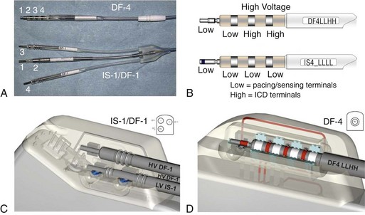
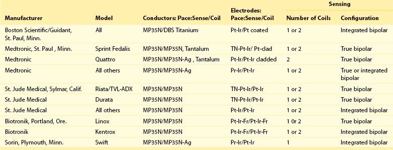
115 The physical components of the implanted system consist of the ICD generator, the pacing and sensing electrodes, and one or more high-energy electrodes. The titanium casing of the ICD generator usually constitutes one of the high-energy electrodes. The electrodes, or leads, attach to the generator header through sealed connectors. Until recently, the ICD leads all divided into one bipolar IS-1 (bradycardia) and one or two defibrillation (DF)-1 (high energy) connectors that are inserted into the ICD generator header. A fully approved (March 15, 2010) International Organization for Standardization (ISO) standard (ISO 27186) implemented by several manufacturers is the DF-4 connector standard that is also 3.2 mm, but combines the connection into a single connector for both low-energy (pacing and sensing) and high-energy (shocking) electrode function. The older IS-1/DF-1 lead design is bulky in the device pocket and adds to the length of the lead. In addition, the trifurcation or bifurcation of the lead also creates the potential for errors in making connections to the header. A similarly constructed (IS-4) connection standard is also implemented for quadripolar low-voltage leads. This standard is implemented only for left ventricular cardiac venous leads and permits noninvasive programming of the pacing vectors after the incision is closed. The IS-4 for LV leads and DF-4 for ICD leads are similar but distinct enough not to allow connection errors in the header (Figure 115-1). Figure 115-1 DF-4/IS-4 lead design. A, DF-4 lead design eliminates the yoke and the redundant lead formation seen in the IS-1/DF-1 design. 1, distal pace/sense electrode; 2, proximal pace/sense electrode; 3, distal DF-1 coil electrode; 4, proximal DF-1 coil electrode. B, IS-4 lead design is similar to DF-4 lead design except that all electrodes are pace/sense low-voltage electrodes. C, IS-1/DF-1 lead connector has three setscrews with the sealing rings built on the lead. D, DF-4/IS-4 connector has a single setscrew that secures on the tip of the lead with spring contacts for the ring and DF electrodes. Inside the DF-4 connector, there are double-sealing rings (blue) between electrodes to secure good isolation between the high- and low-voltage electrode insulation. Nonthoracotomy ICD leads (NTLs) were designed to carry high defibrillation energy to the inside of the heart. These leads can have a dedicated proximal sensing/pacing ring electrode (true bipolar) or use the distal high-voltage shocking coil as the proximal sensing/pacing electrode (integrated bipolar). True bipolar leads usually offer better discrimination for sensing, being less susceptable to far-field oversensing and postshock undersensing. On the other hand, integrated bipolar leads offer better defibrillation performance because of the shorter tip-to–distal coil distance. NTL leads can have one right ventricular (single coil) or two (dual coil) high-voltage shocking electrodes. The distal coil is usually placed in the right ventricular apex, and the proximal coil is placed in the superior vena cava. Although the dual-coil ICD lead system have predominated in the United States and Europe, its clinical superiority over the single-coil lead system is not well established. Defibrillation efficiancy is slightly improved, usually by 1 to 3 J.1 The effect of the dual-coil ICD lead on defibrillation threshold is multifactorial: altered defibrillation electrical field vector, lowered shock impedance, and an on shortening the shock waveform duration. However, this small benefit needs to be weighed against the added complexity of lead construction and its potential effect on lead reliability, as well as the potential for more complex extraction when needed. In addition, the lower right atrial position of the proximal coil, in the case of severely enlarged right ventricle, can increase DFT by a negative current vector effect. In other patients, there is a need to implant other coils (coronary sinus, middle cardiac vein, subcutaneous coil, or azygous coil) when maximal shocks are ineffective; this is almost always more effective in reducing the required defibrillation energy by 5 to 15 J.2 Invariably, NTLs have a high-energy coil located near the distal end and lying within the right ventricular cavity. Manufacturers have released NTLs with similar construction, although some details differ (Table 115-1). The physics of DC flow, however, requires at least one other electrode to complete the shocking circuit. The development of smaller ICD generators has allowed for pectoral implantation, which has enabled the use of the generator casing as the second electrode (i.e., “hot can”). An animal study compared the defibrillation efficacy of a hot can ICD system placed in the left pectoral or subaxillary location with a right pectoral location, and left or right abdominal locations. The left pectoral and axillary subcutaneous positions were superior to all other locations. The right pectoral location was superior to either abdominal location. These results imply that alternative ICD implantation sites are feasible in the event of an inability to implant a left prepectoral device: left subclavian venous occlusion, history of left mastectomy or radiation, left sided arteriovenous fistula, or other reasons to avoid the left prepectoral area.
Implantable Cardioverter Defibrillators
Technical Aspects
System Elements

Nonthoracotomy or Transvenous Leads
Implantable Cardioverter Defibrillators: Technical Aspects


