Implantable Cardioverter Defibrillators: Technical Aspects

115


Implantable Cardioverter Defibrillators


Technical Aspects


Implantable cardioverter defibrillators (ICDs) have revolutionized the treatment of malignant ventricular arrhyhtmias. Their basic tasks include tachycardia detection and termination. To achieve these tasks, the ICD relies on complex integral steps inlcuding sensing of myocardial potentials, delivering these signals to the ICD circuitary board to be filtered and analyzed, and delivering life-saving therapies back to the heart. This chapter outlines the technical aspects of these life-saving devices, including those of the programmer, diagnostics, and telemetry.


System Elements


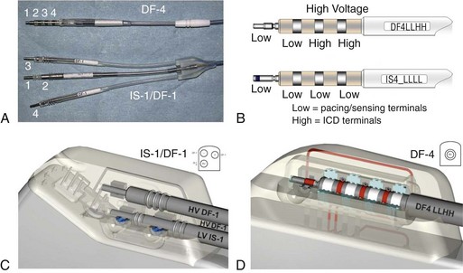
The physical components of the implanted system consist of the ICD generator, the pacing and sensing electrodes, and one or more high-energy electrodes. The titanium casing of the ICD generator usually constitutes one of the high-energy electrodes. The electrodes, or leads, attach to the generator header through sealed connectors. Until recently, the ICD leads all divided into one bipolar IS-1 (bradycardia) and one or two defibrillation (DF)-1 (high energy) connectors that are inserted into the ICD generator header. A fully approved (March 15, 2010) International Organization for Standardization (ISO) standard (ISO 27186) implemented by several manufacturers is the DF-4 connector standard that is also 3.2 mm, but combines the connection into a single connector for both low-energy (pacing and sensing) and high-energy (shocking) electrode function. The older IS-1/DF-1 lead design is bulky in the device pocket and adds to the length of the lead. In addition, the trifurcation or bifurcation of the lead also creates the potential for errors in making connections to the header. A similarly constructed (IS-4) connection standard is also implemented for quadripolar low-voltage leads. This standard is implemented only for left ventricular cardiac venous leads and permits noninvasive programming of the pacing vectors after the incision is closed. The IS-4 for LV leads and DF-4 for ICD leads are similar but distinct enough not to allow connection errors in the header (Figure 115-1).


The DF-4 connector design provides a single setscrew that secures on the tip of the lead with spring contacts for the ring and DF electrodes. Inside the DF-4 connector, there are double-sealing rings between electrodes to secure good isolation between the high- and low-voltage electrode insulation. These sealing rings have been moved from the electrode to the connector block to prevent any damage that occurs during lead implantation.


The advantages of DF-4 design include quicker connections to the ICD because of the single terminal pin, improved patient comfort and satisfaction, and easier reoperations with decreased debridement because of shorter and less complex lead body in the pocket. The risk of procedural errors, such as set screw stripping, untightenned set screws, and port mismatch (switching RV/SVC DF-1 electrodes), should decrease. Subcutaneous tunneling (submammary implant) may be easier as well.


The potential limitations to this lead design are initially the lack of adapters for including additional high- or low-voltage leads, including subclavian, subcutaneous, azygous vein, or coronary sinus coils for high defibrillation threshold (DFT) patients. As with any change, there are potential unidentified reliability risks, but this development was carefully designed and tested over a decade of research.


Implantable Cardioverter Defibrillator Generator


Implantable cardioverter defibrillator generators have decreased significantly in size because of significant advancements in battery and microprocessor technologies. Most of the volume of current ICDs is occupied by its battery and capacitors. The newest generations of devices have added device-initiated long-range telemetry device interrogation, automatic alert notifications, bioimpedance measurement capability, and other advanced features.


Current devices provide for all these options with a generator volume of approximately 30 mL. The ICD generator casing is made of electrically active titanium, considered to be the preferred material, because of its conductivity, strength, biocompatability, corrosion resistance, and light weight. The casing serves mainly to protect the circuitry from the corrosive effects of body fluids; it also serves as an active high-voltage electrode in many current ICD models. The header is generally made of polymethylmethacrylate, so that the connections with the leads can be visually confirmed during implantation and can be inspected if ICD system troubleshooting is required for component malfunction or suspicion of failure. The lead connections gain access to the ICD circuitry through feed through wires, which penetrate the casing through sealed openings.


The interior of the ICD consists of one or more batteries, capacitors, a direct current (DC)-DC converter, hybrid with microprocessor, telemetry communication coil, and their connections. The sensed ventricular signals, generally 5 to 25 mV in amplitude, enter the generator through the leads, are filtered, and then are analyzed by the algorithms programmed into the hybrid. The hybrid consists of electronic circuitry embedded in a silicon wafer, specifically designed for analysis of these signals and identification of either tachycardia or fibrillation. Once the detection criteria are met, the specific programmed pacing and high-energy shock therapies are then delivered to the patient.


Batteries


Unlike other batteries, ICD batteries have many performance requirements. Besides being compact, the battery must be capable of charging the capacitors by delivering high-energy currents in the range of 75 A to charge the capacitors within seconds, and it must have a low current drain on the order of mA. Factors affecting the current drain include pacing and defibrillation needs and the quiescent current needed for ongoing tasks such as powering the hybrid, monitoring intrinsic rhythm, and logging the data in the memory. In addition, the battery performance over time must be predictable to allow for adequate warnings before it is depleted.


The battery used by most ICD generators is a lithium silver vanadium oxide cell (Li/SVO). There are two kinds of Li/SVO batteries: anode-limited (Li) and cathode-limited (SVO) batteries. Anode-limited limited batteries have two voltage plateaus: an early short-lived one followed later by a long-lived one. Most current ICD batteries are cathode-limited (SVO) batteries and carry a charge of 1000 to 2000 mA-hr and at the beginning of life. The battery generates approximately 3.2 V at full charge. At middle of life, these batteries suffer from inherent internal impedance buildup resulting from the accumulation of a film on the Li electrode. Although this impedance can result in prolonged charge time, pulsing the battery frequently by charging the capacitors is usually sufficient in preventing this phenomenon.


The battery status is generally estimated by its measured output voltage. With significant decline in open circuit voltage and a rise in internal resistance, the ability to deliver adequate current to charge the capacitors becomes impaired causing significant prolongation in charge time; this is called the elective replacement time (ERI) or recommended replacement time. Once the ERI is reached, generator replacement can be scheduled electively, usually within 3 months, depending on the frequency of therapy (which determines the depletion rate). A later indicator, end of life, reflects a significantly lower voltage and indicates a more urgent need for generator replacement because of the associated long capacitor charge times required to achieve appropriate shock energy. In addition to voltage criteria, the time required to charge the capacitors to full energy is also used as a measurement of the battery status, and may activate the elective replacement indicator (ERI). In certain devices, charging the capacitors stops after 20 seconds, and delivers the stored energy as shock therapy. When these devices reach ERI, the stored energy may be significantly less than the programmed energy.


Newer ICDs have encorporated newer battery technologies to improve battery performance and longevity. Balancing the cell to an appropriate electron reduction slows the progression of internal battery impedance overtime. In addition, the development of hybrid cathode batteries (lithium/silver vanadium oxide blended with carbon monofluoride [Li/CFx-SVO]) as well as manganese oxide (lithium manganese dioxide [LiMnO2]) has improved service life and resulted in a stable charge time throughout the lifetime of the battery. In addition, LiMnO2 batteries have no midlife impedance rise and stable voltage during the lifetime of the device, with a slow gradual decay toward an ERI independent of the rate of energy use.


Capacitors


The rate of energy delivery for cardiac defibrillation is much greater than can be delivered directly from ICD batteries. Therefore, capacitors are used to store the energy over longer period of time (seconds) and deliver it over a shorter period of time (milliseconds). Capacitors are measured by their capacitance (C), which is a measure of the amount of electrical charge that the capacitor can store for a given voltage. Multiple capacitors are charged in the parallel configuration from the battery through a DC-DC converter and then connected in series to be able to deliver the stored energy (30 to 80 J) but at high voltages (up to 850 V) within 10 to 20 ms. The rate with which the capacitor is being charged depends on its capacitance (C) and the internal impedance of the battery and the circuitry; however, the rate with which the capacitor delivers its charge to the patient depends on its capacitance (C) and the lead–body impedance.


To achieve high stored charge, current ICDs incorporate new designs such as the use of multiple capacitors in series and the use of capacitors with convoluted surfaces to increase surface area. Most capacitors used in the ICD industry are aluminum and tantalum electrolytic capacitors because of their ability to charge within the prescribed time limitations. With time, the dielectric layer in these capacitors becomes deformed, causing current to flow through it (“capacitor leak”). This leak will result in suboptimal charge and prolonged charge time. Capacitor reformation, in which the capacitors are discharged through a high-impedance circuitry to allow for longer discharge time, will usually regenerate the dielectric layer and fix the leak.


Electrodes


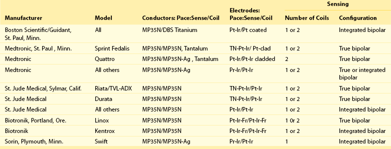
There are three essential functions of defibrillator systems: (1) detection of the tachycardia, (2) pacing stimulation of the heart, and (3) shock stimulation of the heart. The electrodes are the noninsulated segments of the leads that deliver these functions. The technology used for detection (sensing) and pacing is similar to that used by pacemakers; however, the bipole for sensing and pacing is sometimes from the tip of the ventricular lead to the distal shocking electrode instead of from the tip to the ring electrode. This system is an integrated bipolar instead of a true bipolar system. In cardiac resynchronization therapy devices, tachycardia detection is usually restricted to the right ventricular electrodes.


High-voltage coil electrodes are ideal for high-energy shocks. The lower impedance of the coils and the conductor cables to the coils permit a high-current charge discharge from the capacitors. In addition, their wide surface area creates a broader electric field that can enable the defibrillation of more myocardial mass and reduce the current density near the coil.


Nonthoracotomy or Transvenous Leads


Nonthoracotomy ICD leads (NTLs) were designed to carry high defibrillation energy to the inside of the heart. These leads can have a dedicated proximal sensing/pacing ring electrode (true bipolar) or use the distal high-voltage shocking coil as the proximal sensing/pacing electrode (integrated bipolar). True bipolar leads usually offer better discrimination for sensing, being less susceptable to far-field oversensing and postshock undersensing. On the other hand, integrated bipolar leads offer better defibrillation performance because of the shorter tip-to–distal coil distance. NTL leads can have one right ventricular (single coil) or two (dual coil) high-voltage shocking electrodes. The distal coil is usually placed in the right ventricular apex, and the proximal coil is placed in the superior vena cava. Although the dual-coil ICD lead system have predominated in the United States and Europe, its clinical superiority over the single-coil lead system is not well established. Defibrillation efficiancy is slightly improved, usually by 1 to 3 J.1 The effect of the dual-coil ICD lead on defibrillation threshold is multifactorial: altered defibrillation electrical field vector, lowered shock impedance, and an on shortening the shock waveform duration. However, this small benefit needs to be weighed against the added complexity of lead construction and its potential effect on lead reliability, as well as the potential for more complex extraction when needed. In addition, the lower right atrial position of the proximal coil, in the case of severely enlarged right ventricle, can increase DFT by a negative current vector effect. In other patients, there is a need to implant other coils (coronary sinus, middle cardiac vein, subcutaneous coil, or azygous coil) when maximal shocks are ineffective; this is almost always more effective in reducing the required defibrillation energy by 5 to 15 J.2


ICD leads are designed with either coaxial or multilumen constructions. Coaxial design in which layered conductors are separated by layers of polyurethane insulation material—used in some original designs—is no longer used. This design was associated with insulation failure because of metal ion oxidation of the middle polyuerethane insulation layer in the Medtronic Transvene (Minneapolis, MN) family of leads and was manifest by low stimulation impedance and undersensing and oversensing. Current ICD leads use multilumen construction designs in which conductors run in parallel through a single insulating body. However, some variations of this design have been the subject of other failure mechinisms, such as in the case of Sprint Fidelis (Medtronic) and Riata leads (St. Jude Medical [Sylmar, CA]).


Currently available leads either (1) have silicone insulation back filling in between and behind the metal defibrillation coils to decrease tissue ingrowth or (2) have been covered with expanded polytetrafluoroethylene (WL GORE & Associates, (Flagstaff, AZ) ePTFE). This ePTFE coating is slippery, permits the defibrillation current to be transmitted, and prevents tissue ingrowth.


Invariably, NTLs have a high-energy coil located near the distal end and lying within the right ventricular cavity. Manufacturers have released NTLs with similar construction, although some details differ (Table 115-1). The physics of DC flow, however, requires at least one other electrode to complete the shocking circuit. The development of smaller ICD generators has allowed for pectoral implantation, which has enabled the use of the generator casing as the second electrode (i.e., “hot can”). An animal study compared the defibrillation efficacy of a hot can ICD system placed in the left pectoral or subaxillary location with a right pectoral location, and left or right abdominal locations. The left pectoral and axillary subcutaneous positions were superior to all other locations. The right pectoral location was superior to either abdominal location. These results imply that alternative ICD implantation sites are feasible in the event of an inability to implant a left prepectoral device: left subclavian venous occlusion, history of left mastectomy or radiation, left sided arteriovenous fistula, or other reasons to avoid the left prepectoral area.


Tachyarrhythmia Detection


The recognition of tachyarrhythmias by an ICD is a complex interaction of several dependent variables; however, the task of the ICD is more complicated because it must also recognize the lack of tachyarrhythmias. This central insight is crucial, because the patient will spend all but a small fraction of his or her life in a nontachycardia rhythm. Therefore, assuming the efficacy of the pacing and shock therapies, rhythm recognition arbitrates between quality and length of life.


Not all of the factors required for accurate rhythm recognition are potentially affected by the ICD technology. Most notably, the rate and mechanism of the arrhythmia and the programming of the ICD are major determinants of rhythm recognition and are factors that are almost completely independent of the technologic solution. However, by understanding the nature of the signals presented to the ICD, allowing the ICD to adapt to these signals, and limiting programming options, appropriate ICD function is frequently achieved.


Sensing


All current ICDs use ventricular heart rate as the cornerstone variable in tachycardia recognition. To determine heart rate, the interval between each depolarization of the ventricle must be measured. It is not interval recognition but the detection of individual electrogram events that becomes the basic building block in this process. The process begins with the placement of the sensing lead. The sensed electrogram depends on the health of the myocardium in close proximity to the lead, the far-field structures of the diaphragm, anterior chest wall and right atrium, and other electrical devices such as pacemakers, cellular phones, and other sources of electromagnetic interference. Detection of the electrogram events is completely dependent on the quality of the signal, and the quality of the signal is determined primarilly at the time of the lead placement. Additional aspects that are potentially dependent on the position of the lead are measures of electrogram morphology, such as electrogram event width.


In dual-chamber devices, the accurate recognition of arrhythmias adds another layer of complexity and hopefully specificity with the inclusion of atrial lead data input into the generator. The intracardiac location of the atrial lead (far away from the annulus to minimize the far field right ventricular signal) and a short interelectrode distance between the distal and proximal electrodes improve the signal-to-noise ratio of the sensed atrial signal and can thus improve the accuracy of the data used for tachcyardia discrimination.


Band-Pass Filtering


The sense amplifier processes signals presented to the pulse generator by the sensing electrodes and allows signals of certain frequencies to be presented to the detection logic, whereas others are filtered out. This band-pass filter consists of a high-frequency cuttoff to filter out myopotentials signals and a low-frequency cutoff to filter out repolarization T wave signals. The mid range is intended to represent a band of frequency containing true signal events. The intent is to prevent extraneous signals from fooling the device into falsely detecting tachyarrhythmias. Unfortunately, there is some frequency overlap between repolarization and depolarization waves, atrial and ventricular events, postpacing polarization and depolarization of the ventricles, myopotentials and cardiac depolarizations, and environmental signals and cardiac events.


Jun 4, 2016 | Posted by in CARDIAC SURGERY | Comments Off on Implantable Cardioverter Defibrillators: Technical Aspects
Full access? Get Clinical Tree

Get Clinical Tree app for offline access