27 Imaging of Implantable Devices
 Radiography
Radiographs provide essential information about the location, type, and integrity of the pulse generators and leads of both pacing and defibrillation systems. X-ray films also provide basic details of patient anatomy. Interpretation of a chest radiograph should be focused and systematic, with examination of the bony structures, cardiac silhouette, lung fields, trachea, and aorta as well as the presence and location of all preexisting hardware, prosthetic valves, and valve rings or calcification (Fig. 27-1). Abdominal radiographs should be obtained when abdominal device implantation is anticipated.
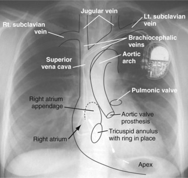
Figure 27-1 Overlay of diagram on posteroanterior chest radiograph.
(From Castle LW, Cook S: Pacemaker radiography. In Ellenbogen KA, Kay GN, Wilkoff BL, editors: Clinical cardiac pacing. Philadelphia, 1995, Saunders, p 538.)
Preprocedural Chest Radiography
Pacemaker/ICD Pulse Generators and Implantable Loop Recorders
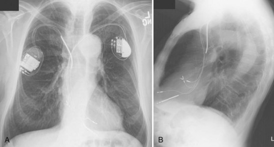
For transvenous systems, the pulse generator is typically located in the subcutaneous, prepectoral region caudal to the clavicle, overlying the pectoralis major muscle. In some patients, the device is located in a subpectoral or submammary position (Fig. 27-2). In pediatric patients and patients with older, larger ICD pulse generators or epicardial ICD lead systems, devices may be located in the abdomen, typically in the left upper quadrant and occasionally in the right upper quadrant or epigastrium (Fig. 27-3). Although most pulse generators are implanted in the subcutaneous region in adult patients, many have been implanted below the rectus abdominis muscle in children and younger women. The pulse generator is also generally implanted abdominally in patients in whom a femoral vein approach is required (Fig. 27-4).
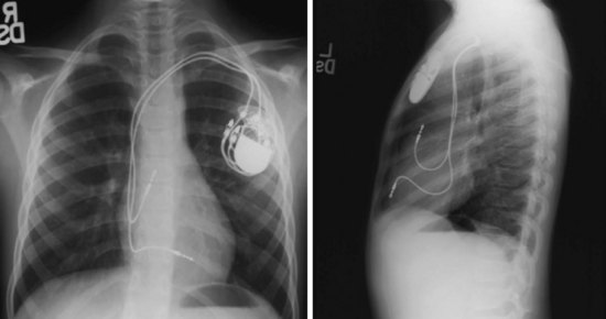
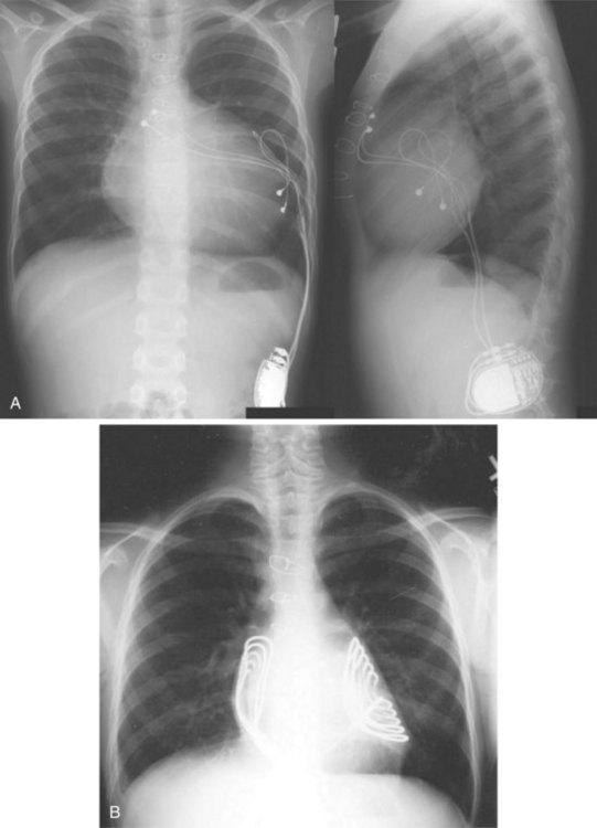

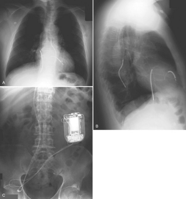
Figure 27-4 Implantable cardioverter-defibrillator with defibrillation leads, including azygos coil lead.
The generator manufacturer and type can be identified from radiography. Most pacemaker and ICD pulse generators have a radiopaque code or logo identifying the manufacturer and model of the device (Figs. 27-5 and 27-6). If the manufacturer can be determined, the proper programmer can be selected. Most current manufacturer programmers can “auto-identify” the specific devices of that manufacturer. Manufacturer technical support divisions may be able to aid in identification of lead systems and devices and can often access device data, such as leads implanted, pacing or shocking configurations, and implant thresholds. Some patients may have both pacing and ICD systems, as well as leads or devices that originate from different manufacturers. Figure 27-7 shows the appearance of implantable loop recorders.
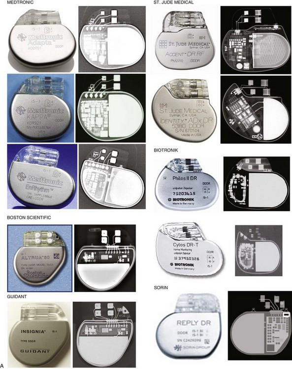
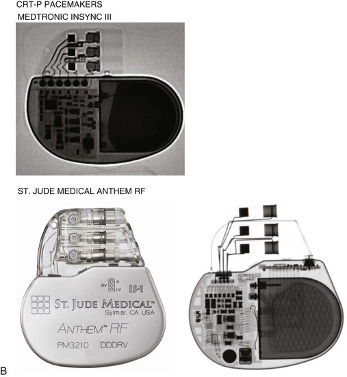
Figure 27-5 Pacing pulse generators and radiographic appearance.
(Courtesy Medtronic, Minneapolis; St. Jude Medical, St. Paul, Minn; Guidant, Boston Scientific, Natick, Mass; Biotronik, Berlin; and ELA/Sorin, Milan.)
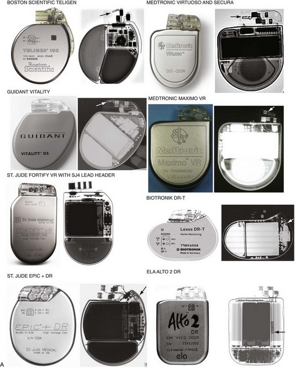
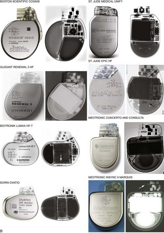
Figure 27-6 Implantable cardioverter-defibrillator (ICD) pulse generators and radiographic appearance.
(Courtesy Guidant, Boston Scientific, Natick, Mass; St. Jude Medical, St. Paul, Minn; Medtronic, Minneapolis; Biotronik, Berlin; and ELA/Sorin, Milan.)
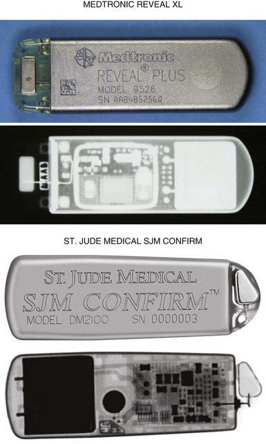
Figure 27-7 Implantable loop recorders.
(Courtesy Medtronic, Minneapolis, and St. Jude Medical, St. Paul, Minn.)
The pacemaker or ICD connector block should be carefully examined radiographically. The connector pins should be advanced beyond the distal pin set-screw blocks (Fig. 27-8). It is usually difficult to determine radiographically whether set screws are in contact with the electrodes. Clues to the polarity of pacing pulse generators include the number and type of connector pins. Determining the type of connector pins (International Standard 1 [IS-1], 3.2-mm Voluntary Standard [VS]-1, 5- or 6-mm, or the new IS-4 connectors) before device replacement avoids an intraoperative discovery that a compatible device is not readily available for the exchange. Radiographically, detection of connector pins that appear longer than the conventional IS-1 pins should prompt checking of lead connector type.
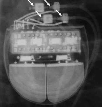
Figure 27-8 Examination of device for lead connector pin insertion into header.
Pins can be visualized extending past the distal connector blocks (arrows).
Migration of the pulse generator may be seen radiographically in older patients with loosened prepectoral fascia, patients who have lost significant amounts of weight, or with pulse generators implanted within larger areas of subcutaneous prepectoral fatty tissue.1
Pacing and Defibrillation Leads
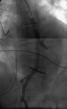
When planning lead revision and/or extraction, one should assess the types, location, and integrity of all leads radiographically. Higher radiographic penetration may be required to more clearly demonstrate lead components. Dislodgment can be identified and is aided by comparison with old films. Leads generally do not have manufacturer-specific, characteristic radiopaque identifiers, but radiography may provide clues to the lead type (active or passive fixation; unipolar or bipolar) and integrity.2
Venous Anatomy for Localization of Lead Positions
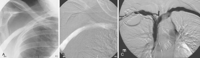
Most pacemaker and ICD leads are inserted transvenously. The subclavian, axillary, and cephalic veins are most often used for lead insertion, with the internal or external jugular or femoral veins used rarely. The cephalic vein courses lateral to the biceps, continuing in a groove between the deltoid and pectoralis major muscles, then empties into the axillary vein (Fig. 27-9). The axillary vein drains the basilic and brachial veins, coursing medially over the lateral margin of the first rib to become the subclavian vein under the clavicle. This marks the usual site for insertion of pacemaker or defibrillator leads (see Fig. 27-1). A change in the directionality of the lead can sometimes indicate the location of the venous insertion site or suture tie-down sleeve. A more lateral insertion site suggests a cephalic or lateral axillary insertion site. Medial insertions into the subclavian vein should be inspected for evidence of lead crush injuries. Lateral axillary insertion sites should be examined for excessive angulation.
After entering the venous system, leads typically pass through the brachiocephalic veins, which are formed by the joining of the internal jugular and subclavian veins behind the head of the clavicle, to the superior vena cava (SVC), and then to the right atrium or right ventricle. In a small percentage of patients, a persistent left SVC is present and drains into the coronary sinus (see later).3
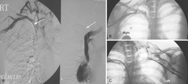
On preparation for a procedure requiring insertion of a new lead, peripheral subclavian and SVC venography can be helpful in anticipating the need for lead extraction or preparation of a new site for venous access because of venous occlusion or severe stenoses (Fig. 27-10). Chronic venous occlusion is often marked by the presence of venous collaterals.
The coronary sinus (CS), which enters the inferior septal region of the right atrium, just anterior and superior to the opening of the inferior vena cava, receives most of the venous drainage of the heart (see Coronary Sinus Lead Positions). The main CS traverses the atrioventricular (AV) groove between the left atrium and left ventricle. Tributaries include the middle cardiac vein; posterior ventricular branch; posterolateral, lateral, and anterolateral marginal branches; and great cardiac vein, which is the extension of the CS beyond the takeoff of the left atrial oblique vein of Marshall. When the vein of Marshall is not present, the valve of Vieussens is used to define the interface of the CS and great cardiac vein. The posterior, posterolateral, and lateral branches of the CS are typical targets for left ventricular or biventricular pacing in CRT devices (see Chapter 22).
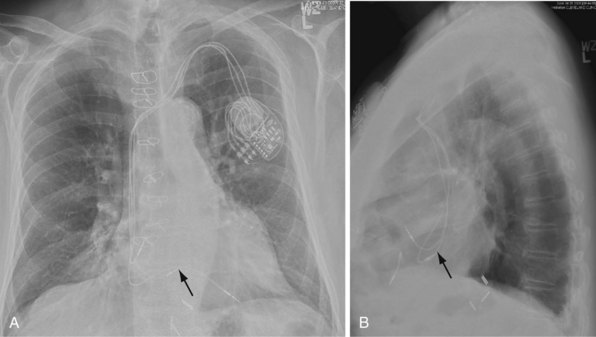
The azygos vein, which enters the posterior wall of the SVC, is sometimes the target vessel for ICD coil-lead implantation in patients with high defibrillation threshold (DFT), as the vessel travels posteriorly behind the heart, providing an additional favorable “shock vector” option4 (Fig. 27-11; see also Fig. 27-4).
Pacemaker Leads
Besides identification of the venous and cardiac insertion sites of pacing leads, chest radiographs can help determine polarity and fixation types. A unipolar lead has a single electrode at the tip of the lead; a bipolar lead has two electrodes separated by a space. Active-fixation leads have screws that extend from the tip of the lead (Fig. 27-12, A). Passive-fixation leads have various types of tines that are radiolucent (cannot be visualized radiographically) (Fig. 27-12, B). Active-fixation leads may be fixed in the extended position or may have an extendable/retractable screw. Different manufacturers denote extension of the latter with various markers (Fig. 27-13).
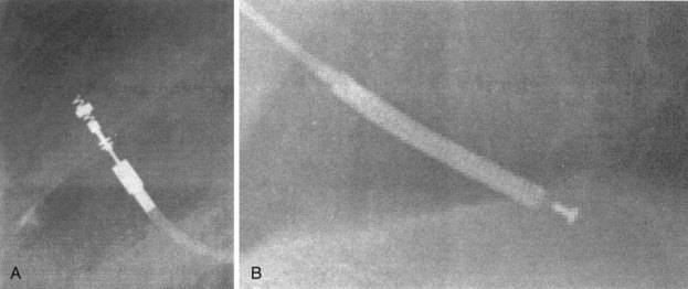
Figure 27-12 Radiographic appearance of transvenous leads.
A, Active-fixation, bipolar lead. B, Passive-fixation ICD lead.
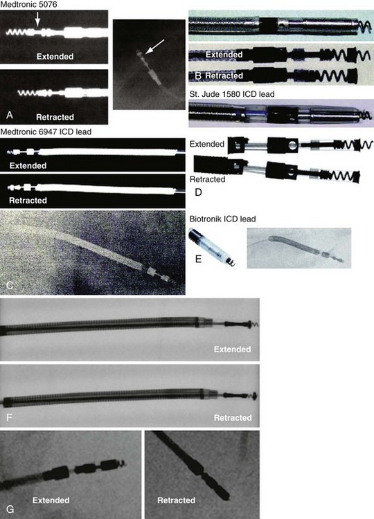
Figure 27-13 Active-fixation screw positions.
(Courtesy Medtronic, Minneapolis; St. Jude Medical, St. Paul, Minn; and Biotronik, Berlin.)
Atrial Lead Positions
In patients who have not undergone cardiac surgery, most atrial leads are fixed to the right atrial (RA) appendage and will exhibit a J shape with an anteriorly directed curve on the lateral view.5 Patients who have undergone cardiac surgery may not have suitable RA appendage remnants for fixation. Lead placement is generally guided by optimization of electrical characteristics, such as sensing and pacing thresholds and lead fixation stability. Leads may be implanted laterally, septally, caudally, or cranially in the right atrium, generally requiring active-fixation leads. Although most pacing systems use one atrial lead, pacing for atrial arrhythmia suppression may incorporate alternative-site or dual-site pacing.6,7 Placements targeting Bachmann’s bundle or the RA septum typically display lead tips directed near the high septum of the right atrium.8,9 The CS or septum near the CS may also be targeted; leads placed in the CS generally exhibit a large, open posterior curve. Higher posterior crossings on lateral films may suggest passage of the lead through a patent foramen ovale or atrial septal defect to the left atrium or ventricle.10
Ventricular Lead Positions
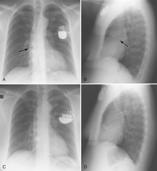
Ventricular pacing leads have traditionally been targeted to the right ventricular apex (RVA). The lead should display some slack, particularly as it traverses and is lifted by the tricuspid valve. The RVA is generally located to the left of the spine on the PA view with a slight inferior direction. On the lateral view, the lead is usually directed anteriorly (Fig. 27-14), unless the septal aspect of the apex is targeted. A more posterior course suggests positioning in the CS or middle cardiac vein. A large posterior curve suggests possible passage through a patent foramen ovale or atrial or ventricular septal defect to the left ventricle (Fig. 27-15).
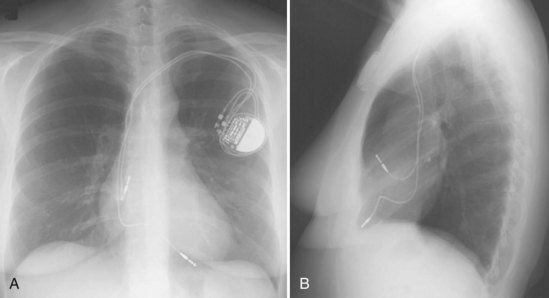
Figure 27-14 Ventricular pacing lead position in right ventricular apex and atrial lead in right atrial appendage.
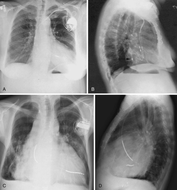
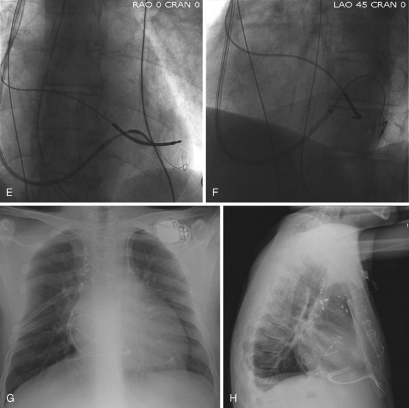
Figure 27-15 Abnormal lead placement into left ventricle.
(A and B from Trohman RG, Wilkoff B, Byrne T, Cook S: Successful percutaneous extraction of a chronic left ventricular pacing lead. Pacing Clin Electrophysiol 14:1448, 1991.)
Although the RVA has been the traditional site for ventricular pacing lead placement, awareness of the potential for left ventricular (LV) dyssynchrony from RVA pacing has led to more frequent use of right ventricular outflow tract (RVOT) or septal pacing11 (Fig. 27-16). A position away from the RVA may also be sought when there are high pacing thresholds at the apex or if an ICD lead is present at the apex, to avoid device-device interactions (Fig. 27-17). His bundle pacing has been proposed as an alternative to RVA pacing in the absence of infra-Hisian conduction system disease12 (Fig. 27-18). An extra set of bipolar sensing electrodes at the level of the right atrium on a ventricular lead body identifies a VDD single-lead pacing system, which is designed to sense in the atrium and allow atrial-synchronous ventricular pacing (Fig. 27-19).
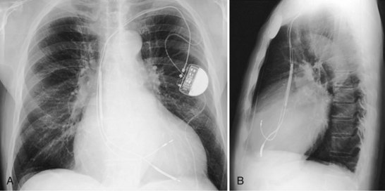
Figure 27-16 Ventricular pacing lead position in right ventricular outflow tract.
(Courtesy Walid Saliba, MD.)
Coronary Sinus Lead Positions
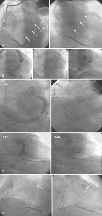
The branches of the CS are common targets for leads placed for LV or biventricular pacing for CRT.13 Placement of the CS lead involves localization and cannulation of the CS, CS venography, and placement of the lead in the target branch. Coronary sinus ostium (CS os) cannulation is accomplished using an angiographic approach or electrophysiologic approach. Angiographic technique involves the use of a variety of guiding sheaths and diagnostic catheters (described in Chapter 22) with boluses of contrast agent for locating the CS os. The EP technique involves the use of guiding sheaths with mapping catheters to help determine the presence of CS recordings on intracardiac electrograms.
After gaining access to the CS, the outer guide sheath is advanced into the proximal portion of the CS at least 3 to 4 cm over a guidewire or a softer inner catheter to prevent mural dissection. Balloon occlusion with contrast venography can then identify potential target tributaries, strictures, and collateral vessels in selection of an optimal target vessel (Fig. 27-20). Balloon inflation must be performed with caution to avoid overinflation and dissection of the vein. After visualization of the distal vessels, the balloon is deflated to promote proximal runoff, allowing visualization of tributaries proximal to the balloon tip. Continued acquisition of images for a few extra seconds after contrast injection allows flow to tributaries through collaterals, which might highlight the posterior and posterolateral LV veins that could otherwise go unnoticed. Two radiographic planes are helpful for assessing the CS tributaries and ostia for optimal target vessel determination. The most common positions used are left anterior oblique (LAO) 25 to 45 degrees, AP, and right anterior oblique (RAO) 15 to 30 degrees.
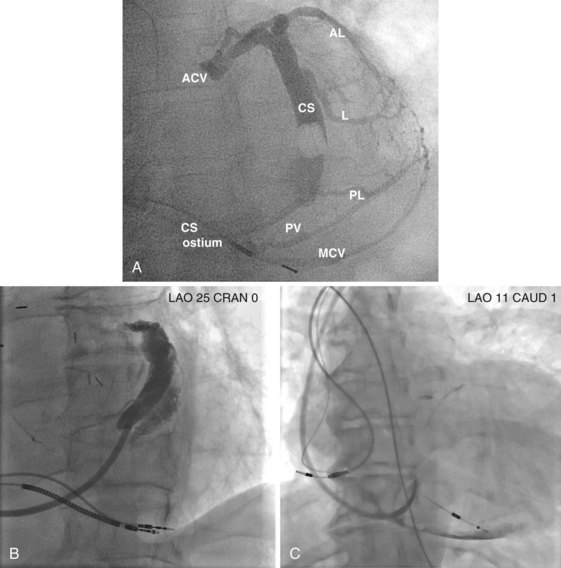
Coronary sinus anatomy is variable, and no consensus exists regarding the nomenclature of CS branch anatomy; as discussed earlier, however, common terminology is used, as depicted in Figure 27-20. From the CS ostium, the first branch is the middle cardiac vein (MCV), near which a posterior ventricular branch may enter. The distal CS becomes the great cardiac vein (GCV) after the takeoff of the vein of Marshall/valve of Vieussens. The GCV terminates at the takeoff of the anterior cardiac vein (ACV), which courses down the anterior interventricular groove. Between the MCV and ACV, posterior, posterolateral, lateral, anterolateral, and anteroseptal branches may be present. Using clock face positions as viewed in LAO projection, the CS os generally is located at 7 o’clock, the MCV at about 6 o’clock, the posterolateral veins at 5 o’clock to 2 o’clock, and GCV/ACV at 12 o’clock. If present, a persistent left SVC drains into the CS directly.14 Figure 27-21 illustrates typical lead tip positions.