3
Event-Related Potentials
Event-related potentials (ERPs) were first explained in 1964 [1,2], and have remained as a useful diagnostic tool, in both psychiatry and neurology. In addition, they have been widely used in brain–computer interfacing (BCI).
ERPs are those EEGs that directly measure the electrical response of the cortex to sensory, affective, or cognitive events. They are voltage fluctuations in the EEG induced within the brain, as a sum of a large number of action potentials (APs) that are time locked to sensory, motor, or cognitive events. They are typically generated in response to peripheral or external stimulations, and appear as somatosensory, visual, and auditory brain potentials, or as slowly evolving brain activity observed before voluntary movements or during anticipation of conditional stimulation.
ERPs are quite small (1–30 µV) relative to the background EEG activity. Therefore, they often need the use of a signal-averaging procedure for their elucidation. In addition, although evaluation of the ERP peaks does not result in a reliable diagnosis the application of ERP in psychiatry has been very common and widely followed.
The ERP waveform can be quantitatively characterized across three main dimensions: amplitude, latency, and scalp distribution [3]. In addition, an ERP signal may also be analysed with respect to the relative latencies between its subcomponents. The amplitude provides an index of the extent of neural activity (and how it responds functionally to experimental variables), the latency (i.e. the time point at which peak amplitude occurs) reveals the timing of this activation, and the scalp distribution provides the pattern of the voltage gradient of a component over the scalp at any time instant.
The ERP signals are either positive, represented by the letter P, such as P300, or negative, represented by the letter N, such as N100 and N400. The digits indicate the time in terms of milliseconds after the stimuli (audio, visual, or somatosensory). The amplitude and latency of the components occurring within 100 ms after stimulus onset are labelled oxogenous, and are influenced by physical attributes of stimuli such as intensity, modality, and presentation rate. On the other hand, endogenous components such as P300 are nonobligatory responses to stimuli, and vary in amplitude, latency, and scalp distribution with strategies, expectancies, and other mental activities triggered by the event eliciting the ERP. These components are not influenced by the physical attributes of the stimuli.
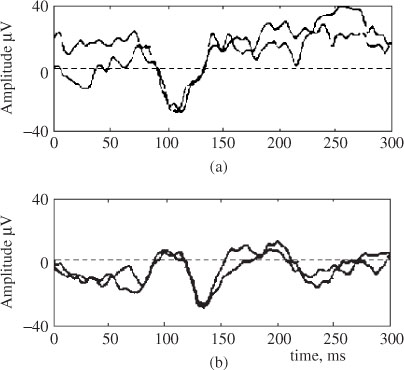
An analysis of event-related potentials, such as visual event potentials (VEPs), within the EEG signals is important in the clinical diagnosis of many psychiatric diseases such as dementia. Alzheimer’s disease, the most common cause of dementia, is a degenerative disease of the cerebral cortex and subcortical structures. The relative severity of the pathological changes in the associated cortex accounts for the clinical finding of diminished visual interpretation skills with normal visual acuity. Impairment of visuocognitive skills often happens with this disease. This means the patient may have difficulties with many complex visual tasks, such as tracing a target figure embedded in a more complex figure or identifying single letters that are presented briefly and followed by a pattern-making stimulus. A specific indicator of dementia is the information obtained by using a VEP. Several studies have confirmed that flash VEPs are abnormal while pattern VEPs are normal in patients with Alzheimer’s disease. The most consistent abnormality in the flash VEP is the increase in the latency of the P100 component and an increase in its amplitude [4,5]. Other ERP components such as N130, P165, and N220 also have longer latencies in patients with Alzheimer’s disease [6,7]. Figure 3.1 illustrates the shape of two normal and two abnormal P100 components. It is seen that the peak of the normal P100s (normally shown in reversed polarity) has a latency of approximately 106 ms, whereas the abnormal P100 peak has a latency of approximately 135 ms and has lower amplitude.
Figure 3.1 Four P100 components: (a) two normal P100 and (b) two abnormal P100 components. In (a) the P100 peak latency is at approximately 106 ms, whereas in (b) the P100 peak latency is at approximately 135 ms
Although determination of the locations of the ERP sources within the brain is a difficult task the scalp distribution of an ERP component can often provide very useful and complementary information to that derived from amplitude and latency. Generally, two types of topographic maps can be generated: raw voltage (or surface potentials) and current source density (CSD), both derived from the electrode potentials.
The scalp-recorded ERP voltage activity reflects the summation of both cortical and subcortical neural activity within each time window. On the other hand, CSD maps reflect primary cortical surface activity [8,9]. CSD is obtained by spatially filtering the subcortical areas as well as cortical areas distal to the recording electrodes to remove the volume-conducted activity. CSD maps are useful for forming hypotheses about neural sources within the superficial cortex [10].
The fMRI technique has become another alternative to investigate brain ERPs since it can detect the hemodynamic of the brain. However, there are at least three shortcoming with this brain imaging modality: first, the temporal resolution is low; second, the activated areas based on hemodynamic techniques do not necessarily correspond to the neural activity identified by ERP measures; and, third, the fMRI is not sensitive to the type of stimulus (e.g. target, standard, or novel). It is considered that the state of the subject changes due to differences in the density of different stimulus types across blocks of trials. Target P300 refers to the P300 component elicited by events about which the subject has been instructed and to which the subject is required to generate some kind of response. A novel stimulus indicates a sole or irregular stimulus.
The ERP parameters such as amplitude and latency are the indicators of the function of the brain neurochemical systems and can potentially be used as predictors of the response of an individual to psychopharmacotrapy [11]. ERPs are also related to the circumscribed cognitive process. For example, there are interesting correlations between late-evoked positivities and memory, N400 and semantic processes, or the latencies of ERPs and the timing of cognitive processes. Therefore, the ERP parameters can be used as indicators of cognitive processes and dysfunctions not accessible to behavioural testing.
The fine-grained temporal resolution of ERPs has been traditionally limited. In addition, overlapping components within ERPs, which represent specific stages of information processing, are difficult to distinguish [12,13]. An example is the composite P300 wave, a positive ERP component, which occurs with a latency of about 300 ms after novel stimuli, or task-relevant stimuli, which requires an effortful response on the part of the individual under test [12–16].
The elicited ERPs are comprised of two main components: the mismatch negativity (MMN) and the novelty P300. Novelty P300 refers to the P300 component elicited by events about which the subject has not been instructed prior to the experiment. The MMN is the earliest ERP activity (which occurs within the first ten milliseconds after the stimulus) that indicates that the brain has detected a change in a background of brain homogeneous events. The MMN is thought to be generated in and around the primary auditory cortex [17]. The amplitude of the MMN is directly proportional, and its latency inversely related, to the degree of difference between standard and deviant stimuli. It is most clearly seen by subtraction of the ERP elicited by the standard stimulus from that elicited by the deviant stimulus during a passive oddball paradigm (OP), when both of those stimuli are unattended or ignored. Therefore, it is relatively automatic.
The P300 wave represents cognitive functions involved in orientation of attention, contextual updating, response modulation, and response resolution [12,14], and consists mainly of two overlapping subcomponents P3a and P3b [13,16,18 P3a reflects an automatic orientation of attention to novel or salient stimuli independent of task relevance. Profrontal, frontal, and anterior temporal brain regions play the main role in generating P3a, giving it a frontocentral distribution [16]. In contrast, P3b has a greater centroparietal distribution due to its reliance on posterior temporal, parietal, and posterior cingulate cortex mechanisms [12,13]. P3a is also characterized by a shorter latency and more rapid habituation than P3b [18].
Figure 3.2. Typical P3a and P3b subcomponents of a P300 ERP signal and the measurement locations
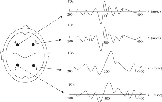
A neural event is the frontal aspect of the novelty P300, i.e. P3a. For example, if the event is sufficiently deviant, the MMN is followed by the P3a. The eliciting events in this case are highly deviant environmental sounds such as a dog barking. Nonidentifiable sounds elicit larger P3a than identifiable sounds. Accordingly, a bigger MMN results in a dominant P3a. Figure 3.2 shows typical P3a and P3b subcomponents. P3b is also elicited by infrequent events, but, unlike P3a, it is task relevant or involves a decision to evoke this component.
The ERPs are the responses to different stimuli, i.e. novel or salient. It is important to distinguish between the ERPs when they are the response to novel or salient (i.e. what has already been experienced) stimuli, or when the degree of novelty changes.
The orienting response engendered by deviant or unexpected events consists of a characteristic ERP pattern, which is comprised sequentially of the mismatch negativity (MMN) and the novelty P300 or P3a. The novelty P3a has two spatial signatures, one frontal the other posterior, each with different cognitive or possibly neurological correlates.
The orienting response [19,20] is an involuntary shift of attention that appears to be a fundamental biological mechanism for survival. It is a rapid response to a new, unexpected, or unpredictable stimulus, which essentially functions as a what-is-it detector [21]. The plasticity of the orienting response has been demonstrated by showing that stimuli, which initially evoked the response, no longer did so with repeated presentation [20]. Habituation of the response is proposed to indicate that some type of memory for these prior events has been formed, which modifies the response to the repeated incidences.
Abnormalities in P300 are found in several psychiatric and neurological conditions [15]. However, the impact of the diseases on P3a and P3b may be different. Both audio and visual P300 (i.e. a P300 signal produced earlier due to an audio or a visual stimulation) are used. Audio and visual P300 appear to be differently affected by illnesses and respond differently to their treatment. This suggests differences in the underlying structures and neurotransmitter systems [13]. P300 has significant diagnostic and prognostic potential, especially when combined with other clinical symptoms and evidences.
In many applications such as human–computer interaction (HCI), muscular fatigue, visual fatigue, and mental fatigue are induced as a result of physical and mental activities. In order for the ERP signals and their subcomponents to be reliably used for clinical diagnosis, assessment of mental activities, fatigue during physical and mental activities, and for provision of the human–computer interface, very effective and reliable methods for their detection and parameter evaluation have to be developed. In the following section a number of established methods for the detection of ERP signals, especially P300 and its subcomponents, P3a and P3b, are explained.
3.1 Detection, Separation, Localization, and Classification of P300 Signals
Traditionally, EPs are synchronously averaged to enhance the evoked signal and suppress the background brain activity [22]. Step-wise discriminant analysis (SWDA) followed by peak picking and evaluation of the covariance was first introduced by Farwell and Dounchin [23]. Later, the discrete wavelet transform (DWT) was also added to the SWDA to localize efficiently the ERP components in both time and frequency [24].
Principal component analysis (PCA) has been employed to assess temporally overlapping EP components [25]. However, the resultant orthogonal representation does not necessarily coincide with the true component structure since the actual physiological components need not be orthogonal, i.e. the source signals may be correlated.
ICA was first applied to ERP analysis by Makeig et al. [26]. Infomax ICA [27] was used by Xu et al. [28] to detect the ERPs for the P300-based speller. In their approach, those ICs with relatively larger amplitudes in the latency range of P300 were kept, while the others were set to zero. Also, they exploited a priori knowledge about the spatial information of the ERPs and decided whether a component should be retained or wiped out. To manipulate the spatial information the ith row and jth column element in the inverse of the unmixing matrix, W−1, is denoted by w′ij therefore, x (n) = W−1u (n). Then the jth column vector of W is denoted by w′j, which reflects the intensity distribution at each electrode for the jth IC uj(n) [26]. For convenience the spatial pattern W−1 is then transformed into an intensity order matrix M = {mij} with the same dimension. The value of the element mij in M is set to be the order number of the value w′ij in the column vector w′j. For example, mij = 1 if w′ij has the largest value, mij = 2 if it has the second largest value, and so on. Based on the spatial distribution of the brain activities, an electrode set Q = {qk} of interest is selected in which qk is the electrode number and is equal to the row index of the multichannel EEG signals x (n). For extraction of the P300 signals these electrodes are located around the vertex region (Cz, C1, and C2), since they are considered to have prominent P300. The spatial filtering of the ICs is simply performed as
where Tr is the threshold for the order numbers. Tr is introduced to retain the most prominent spatial information about the P300 signal. Therefore, ũj(n) holds most of the source information about P300; other irrelevant parts are set to zero. Finally, after the temporal and spatial manipulation of the ICs, the ũj(n), j = 1, 2,…, M, where M is the number of ICs, are backprojected to the electrodes by using W−1 to obtain the scalp distribution of the P300 potential, i.e.
where  (n) is the P300 enhanced EEG. The features of
  (t) can then be measured for classification purposes [28].
3.1.1 Using ICA
ICA has also been used for the detection of P300 signals by Serby et al. [29]. Their work involved the application of a matched filter together with averaging and using a threshold technique for detecting the existence of the P300 signals. The block diagram in Figure 3.3 shows the method.
The IC corresponding to the P300 source is selected and segmented to form overlapping segments from 100 to 600 ms. Each segment is passed through a matched filter to give one feature that represents the maximum correlation between the segment and the average P300 template. However, the very obvious problem with this method is that the ICA system is very likely to be underdetermined (i.e. the number of sources is more than the number of sensors or observations) since only three mixtures are used. In this case the independent source signals are not separable.
3.1.2 Estimating Single Brain Potential Components by Modelling ERP Waveforms
The detection or estimation of evoked potentials (EPs) from only a single-trial EEG is very favourable since on-line processing of the signals can be performed. Unlike the averaging (multiple-trial) [30] scheme, in this approach the shape of the ERPs is first approximated and then used to recover the actual signals.
A decomposition technique that relies on the statistical nature of neural activity is one that efficiently separates the EEGs into their constituent components, including the ERPs. A neural activity may be delayed when passing through a number of synaptic nodes, each introducing a delay. Thus, the firing instants of many synchronized neurons may be assumed to be governed by Gaussian probability distributions. In a work by Lange et al. [22] the evoked potential source waveform is assumed to consist of the superposition of p components ui delayed by τi:
Figure 3.3 Block diagram of the ICA-based algorithm [29]. Three recorded data channels Cz, Pz, and Fz are the inputs to the ICA algorithm

The model equation for constructing the measured data from a number of delayed templates can be given in the z-domain as
where X(z), T(z), and E(z) represent the observed process, the average EP, and a Gaussian white noise respectively. Assuming that the background EEG is statistically stationary, W(z) is identified from prestimulus data via AR modelling of the prestimulus interval, and used for poststimulus analysis [22]. The template and measured EEG are filtered through the identified W(z) to whiten the background EEG signal and thus a closed-form LS solution of the model is formulated. Therefore, the only parameters to be identify are the matrices Bi(z). This avoids any recursive identification of the model parameters. This can be represented using a regression-type equation as
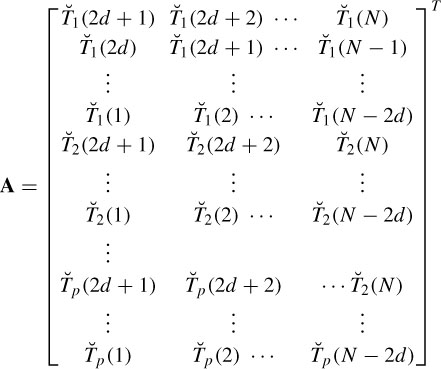
where d denotes the delay (latency), p is the number of templates, and  (n) and Ť (n) are whitened versions of x(n) and T(n) respectively. Let AT be the matrix of input templates and bT be the filter coefficient vector. Then
and
The model can also be expressed in vector form as
where ε is the vector of prediction errors:
To solve for the model parameters the sum-squared error, defined as
is minimized. Then, the optimal vector of parameters in the LS sense is obtained as
The model provides an easier way of analysing the ERP components from single-trial EEG signals and facilitates tracking of amplitude and latency shifts of such components. The experimental results show that the main ERP components can be extracted with high accuracy. The template signals may look like those in Figure 3.4.
Figure 3.4 The ERP templates including a number of delayed Gaussian and exponential waveforms
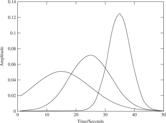
A similar method was also developed to detect and track the P300 subcomponents, P3a and P3b, of the ERP signals [31]. This is described in the following section.
3.1.3 Source Tracking
The major drawback of BSS and dipole methods is that the number of sources needs to be known a priori to achieve good results. In a recent work [31] the P300 signals are modelled as spike-shaped Gaussian signals. The latencies and variances of these signals are, however, subject to change. The spikes serve as reference signals on to which the EEG data are projected. The existing spatiotemporal information is then used to find the closest representation of the reference in the data. The locations of all the extracted components within the brain are later computed using the least-squares (LS) method. Consider the q × T EEG signals X where ne is the number of channels (electrodes) and T the number of time samples; then
where H is the ne × m forward mixing matrix and si(n) are the source signals. Initially, the sources are all considered as the ERP components that are directly relevant and timelocked to the stimulus and assumed to have a transient spiky shape. Then m filters {wi} are needed (although the number of sources are not known beforehand) to satisfy
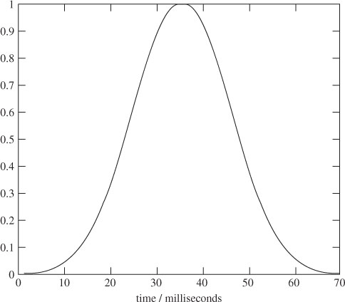
Figure 3.5 A spike model of the P300 sources. The amplitude and latency of this spike are subject to change
This can be achieved by the following minimization criterion:
where X = [x(1), x(2), …, x(T)], which requires some knowledge about the shape of the sources. A Gaussian-type spike (such as that in Figure 3.5) defined as
where τi, i = 1, 2, …, T, is the latency of the ith source and σi is its width, can be used as the model. The width is chosen as an approximation to the average width of the P3a and P3b subcomponents.
Then for each of the T filters (T >> m)
where (.)T denotes the transpose operation. Therefore, each yl has a latency similar to that of a source. Figure 3.6 shows the results of the ERP detection algorithm. It can be seen that all possible peaks are detected first, but because of the limited number of ERP signals these outputs may be grouped into m clusters. To do that the following criteria for the latencies of the ith and i − 1th estimated ERP components are examined according to the following rule:
for l = 1 to T,
Figure 3.6 The results of the ERP detection algorithm [31]. The scatter plot shows the peaks at different latencies
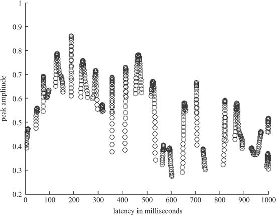
if l(i) − l(i−1) < β, where β is a small empirical threshold, then yi and yi−1 are assumed to belong to the same cluster;
if l(i) − l(i−1) < β then yi and yi−1 belong to different clusters.
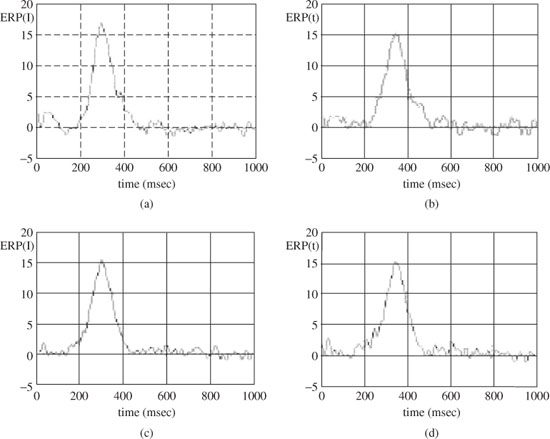
Here l(i) denotes the latency of the ith component. The signals within each cluster are then averaged to obtain the related ERP signal, yc, c = 1, 2,…, m. Figure 3.7 presents the results after applying the above method to detect the subcomponents of a P300 signal from a single trial EEG for a healthy individual (control) and a schizophrenic patient. From these results it can be seen that the mean latency of P3a for the patient is less than that of the control. The difference, however, is less for P3b. On the other hand, the mean width of P3a is less for the control than for the patient, whereas the mean width of the P3b is more for the patient than that of the control. This demonstrates the effectiveness of the technique in classification of the healthy and schizophrenic individuals.
3.1.4 Localization of the ERP
In addition to the above tracking method, in order to investigate the location of the ERP sources a method based on least squares (LS) can be followed [31]. Using this method, the scalp maps (the column vectors of the forward matrix H) are estimated. Consider
Figure 3.7 The average P3a and P3b for a patient (a) and (b) respectively, and for a healthy individual (c) and (d) respectively
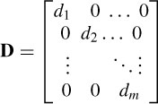
where Y is a matrix with rows equal to yc and Y = DS, where D is a diagonal scaling matrix:
Postmultiplying R by  = YY−1,
The order of the sources is arbitrary; therefore the permutation does not affect the overall process. Hence, the ith scaled scalp map corresponds to the scaled ith source. An LS method may exploit the information about the scalp maps to localize the ERP sources within the brain.
Assuming an isotropic propagation model of the head, the sources are attenuated with the third power of the distance [32], i.e. dj =  , where hj is the jth element of a specific column of the H matrix. The source locations q are found as the solution to the following LS problem:
where aj are the positions of the electrodes, dj are the scaled distances, and M (scalar) is the scale to be estimated together with q. M and q are iteratively estimated according to
and
where µ1 and µ2 are the learning rates and ∇q and ∇M are respectively the gradients with respect to q and M, which are computed as [32]
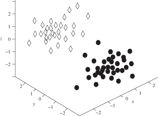
The solutions to q and M are unique given ne ≥ 3 and ne > m. Using the above localization algorithm, 10 sets of EEGs from five patients and five controls are each divided into 20 segments and examined. Figure 3.8 illustrates the locations of P3a and P3b sources for the patients. From this figure it is clear that the clusters representing the P3a and P3b locations are distinct. Figure 3.9, on the other hand, presents the sources for the control subjects. Unlike Figure 3.8, the P3a and P3b sources are randomly located within the brain.
In a recent work by Spyrou et al. [33] a special notch filter (or a beamformer) has been designed to maximize the similarity between the extracted ERP source and a generic spike-shaped template, and at the same time enforce a null at the location of the source. This method is based on a head and source model, which describes the propagation of the brain sources. The sources are modelled as magnetic dipoles and their propagation to the sensors is mathematically described by an appropriate forward model. In this model the EEG signal is considered as an ne × T matrix, where ne is the number of electrodes and T is the number of time samples for an EEG channel signal block:
where H is an ne × 3m matrix describing the forward model of the m sources to the ne electrodes. H is further decomposed into m matrices Hi, as
Figure 3.8 The locations of the P3a and P3b sources for five patients in a number of trials. The diamonds  are the locations of the P3a sources and the circles
  show the locations of P3b sources. The x axis denotes right to left, the y axis shows front to back, and the z axis denotes up and down. It is clear that the classes are distinct
Stay updated, free articles. Join our Telegram channel

Full access? Get Clinical Tree


