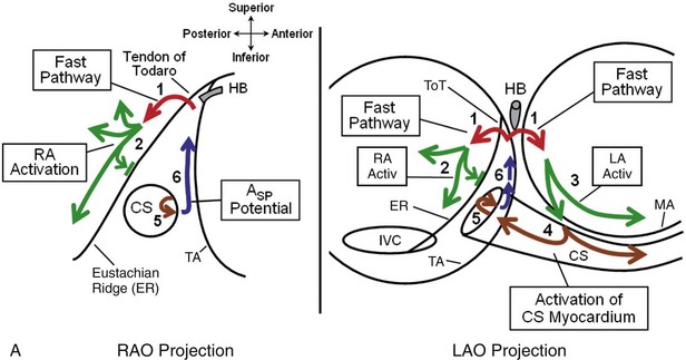
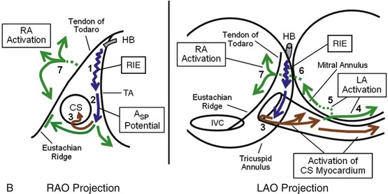
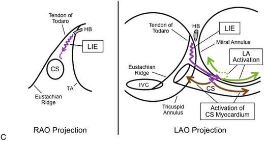
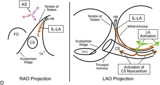
77 Now that more is known about the anatomic substrate for the various forms of AVNRT, the different forms of AVNRT can be distinguished anatomically by the atrionodal connections forming the anterograde and retrograde pathways used in tachycardia. For greater depth and a full bibliography, please refer to the fifth edition of this text.1 Evidence that fast pathway (FP) and slow pathways (SPs) involved in the reentrant circuits of AVNRT represent conduction over different atrionodal connections, rather than functional longitudinal dissociation within the compact AV node, includes the following: (1) different sites of earliest atrial activation during retrograde conduction over the FP and each of the SPs, as originally described by Sung et al2 (Figure 77-1); (2) the ability of a late extrastimulus delivered to the atrium outside the compact AV node to advance the timing in an anterograde slow pathway (advancing or sometimes delaying the next His bundle potential) and to reset the various forms of AVNRT; and (3) the selective elimination of FP or SP conduction by catheter or surgical ablation in the atrium, remote from the compact AV node. The atrial connections of the FP and SPs can be identified by locating the site of earliest atrial activation during selective retrograde conduction over each pathway. All of these sites are located far from the compact AV node. Figure 77-1 Different Atrial Activation Sequence During Retrograde Conduction Over the Fast Pathway (FP) and a Slow Pathway (SP) Formed by the Rightward Inferior Extension of the AV Node (RIE) During retrograde FP conduction, right atrial mapping using closely spaced electrodes (1 mm edge-to-edge) records earliest right atrial activation posterior to the ToT at a level approximately 10 mm inferior to the level recording the proximal His bundle potential (Figure 77-2). The position posterior to the ToT is confirmed radiographically by leftward deviation of the mapping catheter in the left anterior oblique (LAO) projection, indicating that the mapping catheter was not constrained by the tricuspid annulus (TA) and the ToT. If the mapping catheter had been positioned across the ToT, the catheter would have been oriented parallel to the His bundle catheter. Figure 77-2 Pattern of Atrial Activation During Slow/Fast AVNRT During retrograde FP conduction (ventricular pacing or Slow/Fast AVNRT), right atrial activation, beginning posterior to the ToT (outside the ToK), propagates away in the posterior, superior, and inferior directions (green arrows #2 in Figure 77-3, A). Activation propagating inferiorly along the posterior aspect of the Eustachian ridge produces an early far-field atrial potential recorded from the inferior aspect of the ToK (Afar in Figure 77-4). Atrial activation within the ToK (adjacent to the TA) occurs relatively late and proceeds in an inferior-to-superior direction, beginning just outside the CS ostium (blue arrows #6 in Figure 77-3, A and ASP potential in Figure 77-4), and propagates superiorly, producing a second late atrial potential near the apex of the ToK, occurring 50 to 115 ms after earliest atrial activation (2nd A in Figures 77-2, C and 77-5). The two wave fronts, propagating in opposite directions on either side of the ToT (green arrow #2 and blue arrow #6 in Figure 77-3, A), suggest conduction block across the ToT and Eustachian ridge. The timing of the second atrial potential near the apex of the ToK is later than the timing of atrial activation in the inferior ToK (ASP potential recorded between the CS ostium and the TA), which is later than the timing of activation within the proximal CS (see Figures 77-2, C and 77-4). This suggests that tissue within the ToK is activated by the CS myocardium (brown arrows in Figure 77-3, A). Figure 77-3 A, Proposed pattern of atrial activation during retrograde conduction over the FP. Retrograde FP conduction (red arrows, #1) activates the right and left atria at the interatrial septum, posterior to ToT (outside the ToK). Right atrial activation propagates away in the posterior, superior, and inferior directions (RA Activ, green arrows, #2). This results in superior-to-inferior right atrial activation along the Eustachian ridge, outside the ToK. This right atrial wave front is unable to cross the Eustachian ridge and the ToT to enter the ToK, presumably because of conduction block at the Eustachian ridge (short perpendicular green line). Left atrial activation propagates inferiorly (green arrows, #3 in LAO Projection) and activates the CS myocardium, approximately 1 to 3 cm from the ostium (brown arrows). The reentrant impulse propagates along the CS myocardium to the CS ostium (brown arrow #4), where it activates the inferior ToK (brown arrow, #5), producing the ASP potential, with activation proceeding in the inferior-to-superior direction along the inferior ToK (blue arrows, #6). B, Postulated pattern of activation during retrograde conduction over the rightward inferior extension of the AV node (RIE). Retrograde conduction over the RIE (upper blue arrow, #1) activates the myocardium between the inferoseptal TA and the CS ostium (inferior ToK) to produce the retrograde ASP potential (lower blue arrow, #2), and then activates the CS at the floor of the ostium (brown arrows, #3). Activation in the ToK does not cross the Eustachian ridge to the right atrium (perpendicular green line), but proceeds leftward along the CS myocardium (brown arrows in LAO projection) to activate the left atrium. Left atrial activation propagates rapidly in the leftward direction (solid green arrow in LAO projection, #4) but must reverse direction to propagate in the septal direction (dotted green line, #5). The reversal of direction produces late left atrial activation at the left atrial inferoseptal region and a second potential in proximal CS electrograms (recorded from the CS roof). This septal left atrial wave front activates the interatrial septum (dotted green line, #6), which is followed by activation of the right atrium posterior to the ToT and the Eustachian ridge (green arrows, #7), which produces a late far-field potential recorded from the inferior ToK. C, Postulated pattern of activation during retrograde conduction over the leftward inferior extension of the AV Node (LIE). It is unknown whether retrograde conduction over the LIE (purple arrows) initially activates the left atrial myocardium close to the inferoseptal mitral annulus (top purple arrowhead in LAO Projection) or the CS myocardium at the roof of the proximal CS (lower purple arrowhead in LAO Projection). During retrograde conduction over the LIE, CS activation (brown arrows) is recorded earliest at the CS roof, 1 to 3 cm from the ostium. D, Postulated pattern of activation during retrograde conduction over the inferolateral left atrial SP (IL-LA) and the anteroseptal SP (AS). Retrograde conduction over the IL-LA SP (orange arrows) activates the left atrium close to the inferolateral mitral annulus (green arrows). Right atrial mapping during retrograde conduction over the AS SP (pink arrows) records earliest activation at the anterior-superior aspect of the septum or medial right atrial free-wall. FO, Fossa ovalis. Figure 77-4 Late Timing of Atrial Activation at the Inferior ToK During Slow/Fast AVNRT Figure 77-5 Two Distinct Sets of Atrial Potentials Recorded in the Proximal His Bundle Electrograms During Slow/Fast AVNRT If only the second of the two potentials is recorded on the His bundle electrogram during Slow/Fast AVNRT (see Figure 77-2, C), this may lead to the erroneous impression that activation is earliest at the inferior ToK or in the CS (retrograde slow pathway conduction) and may suggest the incorrect diagnosis of Slow/Slow AVNRT. This error can be avoided by mapping behind the ToT as well as along the TA and in the CS to identify the true site of earliest activation during AVNRT (see Figure 77-2). Animal studies suggest that the FP may be formed by transitional cells (with action potentials having features intermediate between those of atrial cells and AV nodal cells), which begin in both atria, cross the right and left sides of the ToT, and insert into the AV bundle relatively close to the central fibrous body (i.e., His bundle). As a result, retrograde conduction over the FP results in almost simultaneous activation of both left and right sides of the interatrial septum.1,3 The left atrial wave front propagates around the inferior mitral annulus in the counterclockwise direction, as viewed in the LAO projection (green arrows #3 in Figure 77-3, A), activating the CS myocardium at the roof, 1 to 2 cm from the CS ostium. CS activation propagates in both lateral and septal directions (brown arrows #4 in Figure 77-3, A). The septal wave front activates the inferior ToK (brown arrow #5 in Figure 77-3, A), resulting in activation in the superior direction in the ToK (blue arrow #6, ASP). A study in isolated perfused canine hearts found that anterograde conduction block in the FP occurred posterior to the ToT.1 As the atrial pacing rate was increased, block occurred at progressively more proximal locations, that is, closer to the anterior limbus of the fossa ovalis. Anterograde FP block may therefore occur outside of the ToK, which may prevent retrograde invasion of the SP, allowing anterograde conduction over one of the SPs, and thus facilitating initiation of Slow/Fast AVNRT and possibly other forms, such as Slow/Slow AVNRT. At least four atrionodal connections other than the FP participate in various forms of AVNRT, and these atrionodal connections have generally been labeled as SPs. The SP most commonly used in both anterograde and retrograde directions is formed by the rightward inferior extension (RIE) of the AV node (Figure 77-6).4 Detailed mapping during retrograde conduction over the RIE suggests that this structure extends over a long length and connects selectively to the floor of the CS ostium (to connect with the left atrium via the CS myocardium; see Figure 77-3, B). The Eustachian ridge forms a complete line of block to prevent the right atrium from being activated from the ToK (green line parallel to the Eustachian ridge in right anterior oblique [RAO] projection of Figure 77-3, B). The earliest retrograde high-frequency potential (ASP potential) is recorded at the inferior ToK, between the TA and the CS ostium (second complex in Figure 77-1, B; blue arrow #2 in Figure 77-3, B and Figure 77-7, B). Activation is then recorded at the floor of the CS ostium (brown arrow #3 in Figure 77-3, B and CS Myo arrow in floor CSp electrogram in Figure 77-7, B). The CS myocardium propagates the impulse leftward and superiorly, activating the left atrial myocardium approximately 2 to 3 cm from the CS ostium. Left atrial activation proceeds rapidly leftward (green arrow #4 in Figure 77-3, B) while slowly reversing direction to propagate rightward toward the septum (dotted green arrow #5 in Figure 77-3, B). Activation then propagates across the interatrial septum to activate the right atrium behind the ToT (green arrows #6 and #7 in Figure 77-3, B). Right atrial activation proceeds superiorly (behind the ToT) to create the atrial potential in the His bundle electrogram, and inferiorly (behind the Eustachian ridge and CS ostium) to create the late, far-field potential recorded at the inferior ToK (Afar in second complex of Figure 77-1, B and Figure 77-7, B). Late right atrial extrastimuli will advance the atrial potential behind the ToT, without advancing the ASP potential, supporting the presence of conduction block across the ToT and the Eustachian ridge. Figure 77-6 Representation of the Locations of the Rightward and Leftward Inferior Extensions Figure 77-7 Pattern of Atrial Activation During Sinus Rhythm and During Fast/Slow AVNRT Using the RIE for the Retrograde Pathway Conduction block across the Eustachian ridge may also account for the late timing of activation within the ToK during sinus rhythm (ASP potential in Figures 77-1, A and 77-7, A). The two most likely explanations for the late ASP potential during sinus rhythm are that the inferior ToK is activated by either (1) the CS musculature, which is activated from the left atrium (Figure 77-8, A); or (2) the crista terminalis (Figure 77-8, B). Observations that the CS myocardium propagates in a distal-to-proximal direction in the proximal 1 to 2 cm of the CS (CS Myo in Figure 77-7, A), and that the ASP potential is recorded after CS activation in the proximal CS (see Figures 77-1, A and 77-7, A) suggest that the inferior ToK is activated from the CS myocardium (see Figure 77-8, A). Figure 77-8 Schematic Representation of Two Possible Patterns of Activation During Sinus Rhythm That May Explain the Late ASP Potential in the Inferior ToK The leftward inferior extension (LIE) of the AV node is the second most commonly observed SP. During retrograde conduction over the LIE, earliest activation is recorded at the roof of the CS, 1 to 3 cm from the ostium (Figures 77-3, C, 77-9, B, and first beat of Figure 77-10, B), and the H-A interval is usually shorter than when retrograde conduction is occurring over the RIE (see Figure 77-10, B
Electrophysiological Characteristics of Atrioventricular Nodal Reentrant Tachycardia
Implications for the Reentrant Circuits
Anatomic Correlates to the Atrionodal Connections
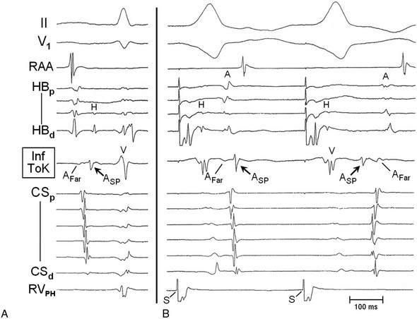
The catheters are in similar position to those in Figure 77-4. Recordings from the top are ECG leads II and V1, and electrograms are recorded from the right atrial appendage (RAA), His bundle region (proximal to distal, HBp to HBd), inferior triangle of Koch (Inf ToK), coronary sinus (proximal to distal, CSp to CSd), and superior basal aspect of the RV septum close to the proximal right bundle branch (para-Hisian RV, RVPH). A, During sinus rhythm, the anterograde ASP potential was recorded after activation in the proximal CS electrograms (CSp) and long after septal activation was recorded in the His bundle electrogram. B, Ventricular pacing (S) from the para-Hisian RV (RVPH). During retrograde conduction over the FP (first beat), early atrial activation (A) is appreciated in the His bundle electrograms (proximal two HB electrograms recorded from behind the tendon of Todaro [ToT]). Activation propagates inferiorly behind the Eustachian ridge to produce an early far-field potential (AFar) in the Inf ToK electrogram. Late activation of the inferior ToK is represented by the sharper ASP potential. Note that the ASP potential is recorded after the timing of activation of the proximal CS myocardium, suggesting that the inferior ToK may be activated from the CS. A similar pattern of activation is seen in the Inf ToK electrogram during sinus rhythm (panel A), with an early far-field atrial potential (AFar) followed by a later ASP potential. In the second beat of panel B, recorded during retrograde conduction over the SP (RIE), the sharp ASP potential is earliest, with later activation behind the Eustachian ridge (AFar) and behind the ToT (A potential in the HBp electrogram). Note that basal septal ventricular pacing from the para-Hisian position, combined with closely spaced bipolar electrodes on the His bundle catheter, results in early completion of the local ventricular potential recorded in the His bundle electrograms and late retrograde activation of the His bundle, allowing visualization of the entire retrograde His bundle potential (H).
Fast AV Nodal Pathway
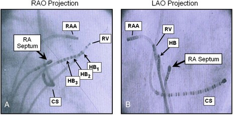
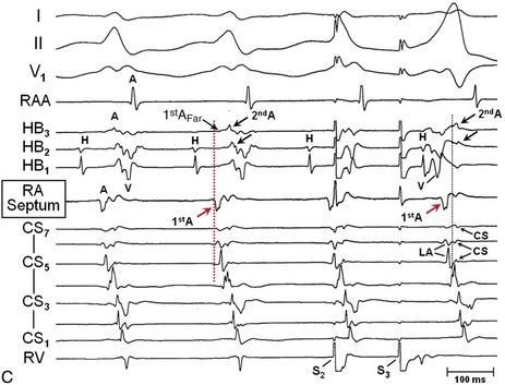
A and B, Radiographs in the right anterior oblique (RAO) and left anterior oblique (LAO) projections, showing the relationship between the His bundle catheter electrodes (HB and HB1–HB3) and catheter electrodes on the right side of the interatrial septum (RA Septum) at the site recording earliest retrograde atrial activation during Slow/Fast AVNRT. The octapolar His bundle catheter (HB) was positioned across the ToT and the tricuspid annulus (TA). The angle for the LAO projection was selected to be parallel with the His bundle catheter (looking straight at the tip). The mapping catheter, RA Septum, was positioned at the site of earliest retrograde right atrial activation during Slow/Fast AVNRT, approximately 1.5 cm posterior and inferior to the site recording most proximal His bundle activation (HB2). In the LAO projection, the mapping catheter (RA Septum) is deviated leftward of the His bundle catheter, confirming a location posterior to the ToT. C, Bipolar electrograms (filter 30 to 500 Hz) recorded with closely spaced electrodes. Two potentials are recorded from the His bundle–RA Septum region. The first potential (1st A; arrows) was recorded behind the ToT (RA Septum). This was the site of earliest activation found during mapping of the right atrium and the CS. A far-field first potential was recorded in the HB3 electrogram (1st AFar; small arrow). The second potential (2nd A) was recorded near the apex of the ToK (electrograms HB3 and HB2). Note that 2nd A propagates in the inferior-to-superior direction (HB3 then HB2; arrows) and is recorded after CS myocardial activation (electrograms CS5-CS7) and 40 ms after earliest atrial activation recorded behind the ToT (1st A).
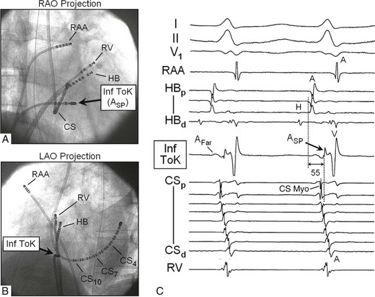
A and B, Radiographs in the RAO and LAO projections show the catheters positioned in the right atrial appendage (RAA), para-Hisian right ventricular pacing site (RV), and CS, and at the inferior ToK, between the mid CS ostium and the TA (Inf ToK). The His bundle catheter (HB) has been positioned across the ToT, with a His bundle potential recorded only on the distal and second HB electrograms, such that the early atrial potentials are recorded from behind the ToT on the proximal electrograms. C, Right atrial activation propagating inferiorly along the posterior aspect of the Eustachian ridge (outside the ToK) produces an early far-field atrial potential recorded from the inferior ToK (Afar) while local activation (within the ToK) is represented as a late sharp ASP potential recorded 55 ms after earliest atrial activation. Modified by permission.7
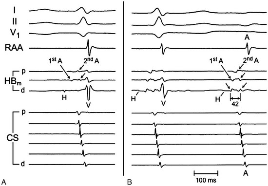
A, The His bundle catheter was positioned to record the proximal His bundle potential from the distal pair of electrodes (HBd electrogram). Two distinct sets of atrial potentials were recorded in the HBm and HBp electrograms. The first set of potentials originate posterior to the ToT, outside the ToK (1st A). The second set (2nd A) are generated close to the TA, inside the ToK. B, The His bundle catheter was withdrawn proximally, such that only a tiny, far-field His bundle potential was recorded in the first complex (H). AV block occurred during the second complex, allowing clear identification of the two sets of atrial potentials in the absence of the ventricular potential. The first set of potentials (1st A) were activated in the distal-to-proximal direction (inferior-to-superior, left arrows in HBd and HBm electrograms). The second set of potentials (2nd A) propagated in the proximal-to-distal direction (superior-to-inferior, right arrows in HBp to HBd electrograms). The time between the first and second atrial potentials in HBd was 42 ms. This delay supports the concept of conduction block across the Eustachian ridge and the ToT.
Rightward Inferior Extension
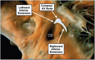
Photograph (right-sided view) of the AV septal junction of a human heart showing the locations of the rightward and leftward inferior extensions of the AV node and the compact node as identified from detailed histologic study. TV, Tricuspid valve. Modified by permission.4
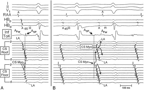
Two catheters with closely spaced bipolar electrodes were positioned along the roof (femoral vein approach) and floor (right subclavian vein approach) of the CS (similar to Figure 77-10). A, During sinus rhythm, atrial activation at the inferior ToK (ASP potential; arrow) was recorded later than atrial activation in the His bundle electrograms and in the roof of the proximal CS (vertical dotted line). B, During Fast/Slow AVNRT, earliest retrograde activation (ASP) was recorded at the Inf ToK region, followed by activation of the floor of the CS ostium (arrow, CS Myo in proximal CS Floor electrogram). Activation propagates laterally along the CS myocardium (proximal-to-distal CS Floor electrograms) and superiorly (to the roof of the CS). The left atrium is activated by the CS myocardium (CS Myo in the CS Roof electrograms). Left atrial activation (LA) then propagates septally and laterally (curved arrows). The late far-field potential (Afar) following the ASP potential in the Inf ToK electrogram results from right atrial activation, posterior to the Eustachian ridge, with timing similar to atrial activation recorded in the His bundle electrograms (A). Note that the A-H interval is shorter during Fast/Slow AVNRT (45 ms) compared with sinus rhythm (65 ms). Modified by permission.9
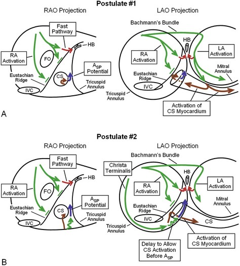
A, Postulate #1: Right atrial activation does not penetrate the ToK because of conduction block across the Eustachian ridge (green arrows and short perpendicular green lines). The left atrium is activated rapidly over Bachmann’s bundle (horizontal green arrow in LAO Projection). Left atrial activation proceeds inferiorly and laterally along the mitral annulus (green arrows), activating the CS myocardium (brown arrows). Activation propagates in the septal direction along the CS myocardium to the CS ostium (brown arrows), and the inferior region of the ToK is activated to generate the late Asp potential (blue arrows). B, Postulate #2: Septal right atrial activation does not cross the Eustachian ridge to activate the ToK (similar to Postulate #1). Activation propagating inferiorly along the Crista Terminalis activates the region between the TA and the Eustachian ridge (sub-Eustachian isthmus, long green arrow in LAO Projection). Continued right atrial activation in the septal and superior direction (short squiggly green arrows) activates the inferior ToK to generate the late Asp potential (blue arrows) and the CS ostium (brown arrows). This postulate does not explain the usual findings that the Asp potential is recorded later than activation at the roof of the proximal CS during sinus rhythm or the distal-to-proximal direction of activation along the roof of the proximal CS.
Leftward Inferior Extension
![]()
Stay updated, free articles. Join our Telegram channel

Full access? Get Clinical Tree


Electrophysiological Characteristics of Atrioventricular Nodal Reentrant Tachycardia: Implications for the Reentrant Circuits
