INDICATIONS AND CONTRAINDICATIONS
Indications
 Acute or rapidly progressing respiratory failure in a patient listed for lung transplantation
 Chronic respiratory failure leading to deconditioning and malnutrition in a patient listed for lung transplantation
 Impending intubation or short time intubated
Contraindications
 Systemic sepsis
 Advanced age
 Serious comorbidities precluding lung transplantation
 Time spent on the ventilator >7 days
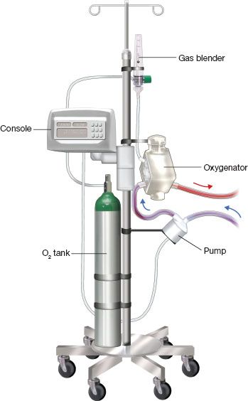
Figure 5.1 ECMO circuit for patient ambulation. The various components are mounted on an IV infusion pole. C, centrifugal pump; O, oxygenator; M, monitoring console; T, oxygen tank with gas blender.
 PREOPERATIVE PLANNING
ECMO circuit components and ambulatory setup (Fig. 5.1)
Principle
Deoxygenated blood is removed from a central vein (femoral or internal jugular vein), pumped through a membrane leading to CO2 removal and oxygenation and returned pre-lung (central vein, right atrium, pulmonary artery) in the case of venovenous (VV) ECMO. In the case of venoarterial (VA) ECMO, blood can be returned to the femoral or axillary artery, left atrium, and the aorta. The carotid artery is usually used for VA ECMO in neonates and infants.
Components
1. Cannulas: Double-lumen flow directed (Avalon Elite; Maquet, San Jose, CA), drainage and perfusion cannulae inserted percutaneously or centrally.
 Cannula size, mainly of the drainage cannula or component, is the major determining factor in total pump flow. Factors taken in consideration for selection are patient size and length.
2. Heparin-bonded (Carmeda; Medtronic, Minneapolis, MN) 3/8″ tubing.
3. Centrifugal pump (CentriMag; Thoratec, Pleasanton, CA or RotaFlow; Maquet, San Jose, CA).
 Connected to monitoring console.
4. Oxygenator (Quadrox: Maquet, San Jose, CA).
 Comprising two chambers (gas and blood) divided by a semipermeable hollow fiber membrane, allowing for carbon dioxide (CO2) and oxygen (O2) diffusion. CO2 is more soluble than O2 and diffuses easily through the membrane. CO2 clearance is, therefore, a result of gas flow (sweep gas) across the membrane. Oxygenation will be determined by pump flow and gas blender (O2/air); pump flow relative to the patient’s cardiac output will be the major determinant of the patient’s PO2.
 Connected to heater/cooler for temperature management.
 SURGERY
Venovenous (VV) ECMO
Venovenous (VV) dual cannulation strategy (Fig. 5.2)
Indication
 Primarily for the patient with respiratory failure as a bridge to recovery or bridge to decision.
Advantages and Disadvantages
 The advantages are: The technique is performed rapidly, often at the bedside, and does not require fluoroscopy or Transesophageal echo (TEE).
 However, there is a higher incidence of recirculation, and as a result, it is difficult to extubate, or mobilize and exercise these patients. For patients in whom the decision is made to list for lung transplantation after the initiation of ECMO, this strategy can be used as a bridge to a different cannulation arrangement.
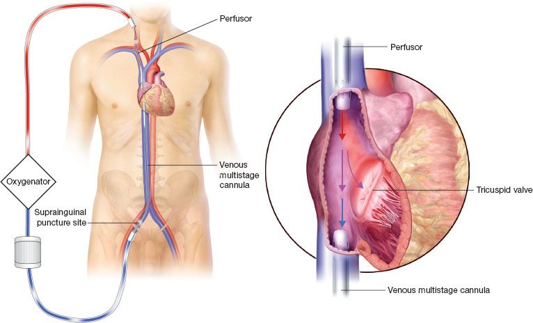
Figure 5.2 Venovenous dual site cannulation. The drainage and perfusor cannulas have to be distanced to prevent recirculation.
Concept: Blood Recirculation Fraction
 With this cannulation arrangement, the inflow and outflow cannulas have to be separated by as much distance as possible to reduce the blood recirculation fraction.
Technique
The right neck and femoral areas are prepped in the sterile field, and the ECMO lines are divided and brought up. Right internal jugular access and femoral venous access (just above the inguinal ligament) are obtained using a 4-Fr micropuncture needle (Cook, Bloomington, IN), Seldinger technique, and 4-Fr introducer.
 100 IU/kg of heparin is administered to the patient
 The femoral vein is usually the site of the drainage cannula. We often choose a long (no. 23 to 25) multistage cannula.
 The right internal jugular vein is usually the preferred site for the insertion of the perfusor cannula. We opt for an arterial no. 19 perfusor cannula.
 Alternate sites for cannulation are the left internal jugular vein and and the subclavian vein, but we recommend that fluoroscopy be used during cannula insertion to prevent vascular injury if these alternate sites are considered.
 After femoral access is obtained, a super-stiff Amplatz (Cook, Bloomington, IN) 0.038″ guidewire advanced to the level of the inferior vena cava (IVC) and right atrial (RA) junction. Successful venous dilatations are performed, followed by the insertion of the venous multistage cannula to the level of the diaphragm to prevent. The cannula is de-aired and connected to the inflow limb of the circuit.
 Using the same technique, the perfusor is inserted and positioned to the level of the SVC-RA junction. Once de-aired and connected to the outflow limb of the ECMO circuit, time-out is performed to verify (1) the flow direction, (2) the absence of air entrapped in the circuit, and (3) adequate anticoagulation with an activated clotting time (ACT). Only then ECMO is initiated.
Caveats
 Recirculation can be significant with this strategy. It can be suspected when a low arteriovenous O2 difference between the inflow and outflow limbs of the circuit. It worsens when pump flows are increased on ECMO. If the patient remains desaturated, it often requires a change in cannulation strategy.
Single cannula (Fig. 5.3): Dual-lumen flow directed cannula (Avalon Elite: Maquet, San Jose, CA)
Concept
A single cannula provides inflow and outflow. The inflow has an IVC and SVC port, and the outflow is flow directed and aimed at the tricuspid valve.
Indication
The best use of this technology is patient optimization prior to lung transplantation.
Advantages and Disadvantages
Stay updated, free articles. Join our Telegram channel

Full access? Get Clinical Tree


