Coronary Angiography
Mauro Moscucci
The contribution of William Grossman and Donald Baim to this chapter in prior editions is gratefully acknowledged.
The initial attempts to perform coronary angiography used nonselective injections of contrast media into the aortic root to opacify both the left and right coronary arteries simultaneously as the angiographic images were recorded on serial conventional sheet films.1 The focus on nonselective angiography was prompted by animal studies, which had shown that selective injection of contrast media in a coronary artery would induce ventricular fibrillation. To improve contrast delivery into the coronary ostia, some early investigators used transient circulatory arrest induced by the administration of acetylcholine or by elevation of intrabronchial pressure, followed by occlusion of the ascending aorta by gas-filled balloons and injection of the contrast bolus. Unfortunately, all these techniques were associated with risks and did not provide a clear opacification of the coronary artery tree. The realization that selective coronary angiography could be performed safely in humans was the result of a serendipitous event that occurred in the Cleveland Clinic Cardiac Catheterization Laboratory in 1958. As described by Dr. Mason Sones in his recollection of that day, he had just performed with his assistant a left ventriculogram and was proceeding to perform an aortogram in a young patient with rheumatic heart disease2:
“I asked my associate to withdraw the catheter tip across the aortic valve into the ascending aorta so that we could complete the procedure by performing an aortogram with the catheter tip in the ascending aorta. My associate complied and we relied on the pressure change from the left ventricle to the ascending aorta without sliding the table top back under the 5 inch amplifier to confirm the exact location of the tip. I didn’t think this was necessary because I was quite certain that the catheter tip lay in the ascending aorta just above the aortic valve. My associate, Dr. Royston Lewis, made an injection of 40 cc of 90% Hypaque through the catheter. About one second before the injection was initiated, I had the switch to initiate a cine run. When the injection began, I was horrified to see the right coronary artery become heavily opacified and realized the catheter tip was actually inside the orifice of the dominant right
coronary artery. I shouted, “Pull it out.” Our combined reaction times to accomplish withdrawal of the catheter consumed 3-4 seconds which meant that approximately 30 cc of 90% Hypaque had been delivered into the right coronary artery. I was of course horrified because I was certain the patient would develop ventricular fibrillation. At that time we did not have direct current defibrillators and knew nothing about the application of closed chest cardiac massage. I climbed out of the hole and ran around the table looking for a scalpel to open his chest in order to defibrillate him by direct application of the paddles of an alternating current defibrillator. I looked at the oscilloscope tracing of his electrocardiogram and it was evident that he was in asystole rather than in ventricular fibrillation. I knew that an explosive cough could produce a very effective pressure pulse in the aorta and hoped that this might push the contrast media through his myocardial capillary bed. Fortunately, he was still conscious and responded to my demand that he cough repeatedly. After 3-4 explosive coughs, his heart began to beat again with initially a sinus bradycardia which accelerated into a sinus tachycardia within 15 to 20 seconds. He then made a perfectly uneventful recovery with no neurological deficit or other sequelae.”
coronary artery. I shouted, “Pull it out.” Our combined reaction times to accomplish withdrawal of the catheter consumed 3-4 seconds which meant that approximately 30 cc of 90% Hypaque had been delivered into the right coronary artery. I was of course horrified because I was certain the patient would develop ventricular fibrillation. At that time we did not have direct current defibrillators and knew nothing about the application of closed chest cardiac massage. I climbed out of the hole and ran around the table looking for a scalpel to open his chest in order to defibrillate him by direct application of the paddles of an alternating current defibrillator. I looked at the oscilloscope tracing of his electrocardiogram and it was evident that he was in asystole rather than in ventricular fibrillation. I knew that an explosive cough could produce a very effective pressure pulse in the aorta and hoped that this might push the contrast media through his myocardial capillary bed. Fortunately, he was still conscious and responded to my demand that he cough repeatedly. After 3-4 explosive coughs, his heart began to beat again with initially a sinus bradycardia which accelerated into a sinus tachycardia within 15 to 20 seconds. He then made a perfectly uneventful recovery with no neurological deficit or other sequelae.”
Fortunately, the patient did not develop ventricular fibrillation, and that inadvertent injection allowed Dr Sones to realize that selective injection of contrast media in coronary arteries was feasible. Two days later, he performed a planned selective injection that marked the beginning of a new era in cardiac catheterization3 (Figure 15.1). For further details on the history and evolution of coronary angiography, interested readers are referred to excellent reviews available in the literature.3, 4, 5
As of today, diagnostic coronary angiography remains the principal component of cardiac catheterization. The goal is to examine the entire coronary tree (both native vessels and any surgically constructed bypass grafts) while recording details of the coronary anatomy, which include the following: the pattern of arterial distribution, anatomic or functional pathology (atherosclerosis, thrombosis, congenital anomalies, or focal coronary spasm), and the presence of intercoronary and intracoronary collateral connections. The procedure is typically performed in 30 minutes or less, under local anesthesia, on an outpatient basis, with a procedure-related major complication rate (death, stroke, myocardial infarction, see Chapter 4) of <0.1%. By performing a series of intracoronary contrast injections in carefully chosen angulated views using current high-resolution x-ray imaging (see Chapter 2), it is possible to define all portions of the coronary arterial circulation down to vessels as small as 0.3 mm, free of any artifacts owing to vessel overlap or foreshortening.
There is currently no other imaging technique that gives as detailed a view of the coronary circulation, although noninvasive techniques such as magnetic resonance angiography (MRA) and coronary computed tomographic angiography (CCTA) have improved their temporal and spatial resolution and emerged as effective screening tests for coronary artery disease, for the evaluation of coronary anomalies and patency of surgical bypass grafts, and more recently for providing additional information regarding nonobstructive coronary artery disease and atherosclerosis burden.6, 7, 8, 9 However, for patients with compelling ischemic symptoms, what begins as a diagnostic procedure can quickly shift to a definitive therapy (percutaneous coronary intervention or PCI, see Chapters 28, 29, 30 and 31) performed through the same access site. Even so, coronary angiography is limited to examination of only the coronary lumen and not of the endothelial surface, plaque content, vessel wall, or (except indirectly) coronary flow physiology. When features related to the above are in question, coronary angiography may be supplemented by intravascular ultrasound, optical computerized tomography, angioscopy, or intracoronary pressure and flow measurements (see Chapters 24 and 25). Despite these limitations, selective coronary angiography still remains the clinical gold standard for evaluating coronary anatomy. Performance of high-quality coronary angiography to safely define each and every coronary stenosis in an optimal view is an important measure of an operator’s skill in cardiac catheterization and is the foundation on which the ability to perform successful coronary intervention is based.
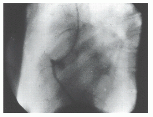 Figure 15.1 Cine frame from the first selective coronary arteriogram taken by F. Mason Sones, MD, on October 30, 1958. (Reprinted with permission from Ryan TJ. The coronary angiogram and its seminal contribution to cardiovascular medicine over five decades. Circulation 2002;106:752-756.) |
CURRENT INDICATIONS
The various current indications for coronary angiography are summarized comprehensively in the AHA/ACC guidelines for coronary angiography and in the recent Appropriate Use Criteria for Diagnostic Cardiac Catheterization.10,11 Although the details of these indications continue to evolve as new applications of catheter-based therapy are developed, they are still best summarized by the principle stated by F. Mason Sones—coronary arteriography is indicated when a problem is encountered whose resolution may be aided by the objective demonstration of the coronary anatomy, provided competent personnel and adequate facilities are available and the potential risks are acceptable to the patient and physician.
The most frequent indication is the further evaluation of patients in whom the diagnosis of coronary atherosclerosis is almost certain and in whom anatomic correction by means of coronary bypass surgery or PCI is contemplated. Angiographic evaluation of coronary anatomy in such patients provides the crucial information needed to select the most appropriate treatment strategy—catheter intervention (see Chapters 28, 29, 30 and 31), bypass surgery, or medical therapy. Included in this category are patients with stable angina pectoris refractory to medical therapy.
Even asymptomatic patients with noninvasive evidence of myocardial ischemia also benefit from revascularization and are thus candidates for coronary angiography.12 In patients with unstable angina (new onset, progressive, or rest pain), intensive drug therapy (beta-blocker, calcium channel blocker, nitrate, heparin, aspirin, clopidogrel or a platelet glycoprotein IIb/IIIa receptor blocker) may be temporizing, but more than two-thirds of such patients will come to angiography within 6 weeks of presentation anyway owing to ongoing clinical symptoms or a positive exercise test.13,14 In most cases, therefore, such patients are brought to early coronary angiography, with same-procedure PCI if their anatomy is suitable. Patients with acute myocardial infarction routinely undergo immediate coronary angiography followed by same-procedure primary angioplasty.15 However, the role of routine post-MI coronary angiography in the asymptomatic postinfarct patient who was managed medically or with thrombolysis has not been established.16 The most recent AHA/ACC guidelines for the role of coronary angiography in stable angina, unstable angina, and acute myocardial infarction are available on the Internet at http://www.cardiosource.org/.
A second group of potential candidates for coronary angiography consists of patients in whom the presence or absence of coronary artery disease is unclear.11 This includes patients with troublesome chest pain syndromes but ambiguous noninvasive test results, patients with unexplained heart failure or ventricular arrhythmias, survivors of out-of-hospital cardiac arrest,17 patients with suspected or proven variant angina,18 and patients with risk factors for coronary artery disease who are being evaluated for major abdominal, thoracic, or vascular surgery.19 This category also includes patients scheduled for correction of congenital or valvular pathology. Patients with congenital defects such as tetralogy of Fallot frequently have anomalies of coronary distribution that may lead to surgical complications if unrecognized,20 whereas patients older than age 45 years with valvular disease may have advanced coronary atherosclerosis without clinical symptoms. Although younger patients with valvular disease are commonly operated on without prior coronary angiograms, given the extraordinary low risk of diagnostic catheterization and the potential benefit of knowing the coronary anatomy, most surgical center personnel believe it is best to perform a preoperative diagnostic catheterization to identify (and then correct) significant coronary lesions, so as to provide the best and safest outcome during concurrent valve replacement.21
Finally, coronary angiography is frequently performed when a patient develops recurrent angina after coronary intervention (to detect and treat restenosis) or after bypass surgery (to detect vein graft failure, which might require catheter intervention or reoperation). Routine follow-up angiography 6 months after catheter intervention is not indicated clinically, but may play an important role in the research evaluation of new technologies or drug therapies targeted at reducing restenosis or atherosclerosis burden.22
GENERAL ISSUES
In the early years, coronary angiography used to be performed using the brachial artery cutdown approach. The development of preshaped catheters and advancements in vascular access techniques have led to a progressive adoption of the percutaneous approach from the femoral, brachial, or radial artery, and as of today brachial cutdown (Chapter 8) is rarely performed. Importantly, over the past 10 years the radial artery percutaneous approach (Chapter 7) has emerged as an alternative to the femoral artery approach. As discussed in detail in Chapter 7, the radial artery approach may offer a selective advantage in patients with severe peripheral vascular disease, morbid obesity, or known abdominal aortic aneurysm, and additional advantages regarding bleeding complications and early ambulation. Regardless of the approach, however, it is important for the catheterization team to meet the patient before the actual procedure to evaluate the best access site, to gain an appreciation of the clinical questions that need to be answered by coronary angiography, to uncover any history of adverse reaction to medications or organic iodine compounds, and to explain the procedure and its risks in detail.
Coronary angiography was traditionally performed with hospitalization for the night after the procedure and sometimes for the night prior to the scheduled procedure as well. In contrast, most patients now come in on the morning of their scheduled procedure, with no oral intake (except for medications and limited quantities of clear liquid) for 6 to 8 hours
before catheterization. A mild sedative premedication (such as diazepam, 5-10 mg orally) may be given prior to the procedure, or intravenous conscious sedation may be administered as needed during the procedure itself. Outpatient coronary angiography for low- to moderate-risk patients began in the 1990s23,24 and is now the dominant practice. However, patients with major comorbidities (e.g., heart failure, valve disease, renal insufficiency, peripheral vascular disease), or those who have sustained a procedural complication might be expected to stay overnight in the hospital following a diagnostic coronary angiogram. If the angiogram shows significant disease and PCI is appropriate, this may be done during the same procedure followed by an overnight hospital stay. Same day hospital discharge following PCI is currently undergoing further evaluation. Patients needing revascularization but not found to be suitable for PCI at the time of coronary angiography may go for a bypass surgical operation within 24 to 48 hours or may be discharged home to return for surgery, depending on clinical acuity and availability of surgical time. At least 2 hours of bed rest is required after a percutaneous femoral procedure unless a puncture sealing device is used (see Chapter 6) to allow earlier ambulation and discharge.
before catheterization. A mild sedative premedication (such as diazepam, 5-10 mg orally) may be given prior to the procedure, or intravenous conscious sedation may be administered as needed during the procedure itself. Outpatient coronary angiography for low- to moderate-risk patients began in the 1990s23,24 and is now the dominant practice. However, patients with major comorbidities (e.g., heart failure, valve disease, renal insufficiency, peripheral vascular disease), or those who have sustained a procedural complication might be expected to stay overnight in the hospital following a diagnostic coronary angiogram. If the angiogram shows significant disease and PCI is appropriate, this may be done during the same procedure followed by an overnight hospital stay. Same day hospital discharge following PCI is currently undergoing further evaluation. Patients needing revascularization but not found to be suitable for PCI at the time of coronary angiography may go for a bypass surgical operation within 24 to 48 hours or may be discharged home to return for surgery, depending on clinical acuity and availability of surgical time. At least 2 hours of bed rest is required after a percutaneous femoral procedure unless a puncture sealing device is used (see Chapter 6) to allow earlier ambulation and discharge.
THE FEMORAL APPROACH
As described in Chapter 6, the femoral approach to left heart catheterization involves insertion of the catheter either directly over a guidewire or through an introducing sheath. A series of preformed catheters are used, starting with a pigtail catheter for left ventriculography followed by separate catheters (either Judkins or Amplatz shapes) for cannulation of the left and right coronary arteries and any surgical bypass grafts. Coronary catheters are available in 4F, 5F, 6F, 7F, or 8F end-hole designs that may taper further near the tip. They may be constructed of polyethylene (Cook Inc, Bloomington, IN), polyurethane (Cordis, Miami, FL), or other high-strength polymer materials such as Trilon (TM, Boston Scientific Natick, MA), which resist softening in the body. They contain steel braid, nylon, or other reinforcing materials (Kevlar, carbon fiber) within the catheter wall to provide the excellent torque control needed for coronary cannulation. Current catheters have a soft distal tip to minimize the risk of arterial dissection. In the 1970s, 8F catheters predominated because they provided excellent torque control and permitted rapid contrast delivery. In the 1980s, improvements in the design of 7F catheters allowed for a lumen diameter comparable to that in standard 8F catheters, making them the standard in most laboratories. Smaller (6F and even 5F and 4F) coronary angiographic catheters are now available that use technology similar to that used in guiding catheters to provide thinner catheter walls and larger lumens (6F lumens up to 0.0.071 inches for guiding catheters), exceeding the lumen size once available in 8F diagnostic catheters. We now use such 6F catheters for all of our routine diagnostic procedures and most interventional procedures. Some of the catheters used for native coronary injection via the femoral or brachial approach are shown in Figure 15.2.
Insertion and Flushing of the Coronary Catheter
The selected catheter is inserted into the femoral sheath and advanced around the arch and into the ascending aorta before the guidewire is removed. Alternatively, the catheter can be advanced to the level of the left mainstem bronchus over the guidewire. This alternative approach, while having the potential to reduce the risk of complications secondary to improper flushing, can result in snagging the catheter tip on aortic wall plaques and irregularities. After removal of the guidewire, the catheter is attached to a specially designed manifold system that permits the maintenance of a closed system during pressure monitoring, catheter flushing, and contrast agent administration (Figure 15.3). The catheter is immediately double-flushed—blood is withdrawn and discarded, after which heparinized saline flush is injected through the catheter lumen. Difficulty in blood withdrawal suggests apposition of the catheter tip to the aortic wall, which can be rectified by slight withdrawal or rotation of the catheter until free blood aspiration is possible. If blood cannot be aspirated despite repositioning the catheter, the catheter should be removed from the body and flushed on a towel, as we have occasionally seen thrombus collected in the catheter during exchanges over a guidewire. The lumen of the introducing sheath should also be flushed immediately before and after each catheter insertion and every 5 minutes thereafter to prevent the encroachment of blood into the sheath. Such encroachment can result in the formation of thrombus, which is then “collected” by the catheter tip during insertion of the catheter in the sheath. Alternatively, the side arm of the sheath may be connected to a 30 mL/hour continuous flow regulator.
Once the catheter has been flushed with saline solution, tip pressure should be displayed on the physiologic monitor at all times (except during actual contrast injections). Recording this baseline pressure before contrast administration serves as an important baseline reference point. Next, the catheter lumen should be gently filled with contrast agent under fluoroscopic visualization, avoiding selective contrast administration into small branches such as the lumbar arteries if filling is performed in the descending aorta. Filling with contrast results in slight attenuation of high-frequency components in the aortic pressure waveform, the new shape of which should be carefully noted. Any subsequent alteration in that waveform during coronary angiography (see damping and ventricularization, below) may signify an ostial coronary stenosis or an unfavorable catheter position within the coronary artery. Once these measures are completed, the coronary angiographic catheter is advanced into the aortic root in preparation for selective engagement of the desired coronary ostium.
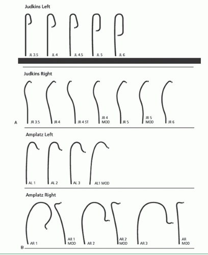 Figure 15.2 Types of catheters currently in wide use for selective native coronary angiography. A. Judkins catheters. B. Amplatz catheters. (Courtesy of Cordis Corporation, Bridgewater, NJ.) |
Damping and Ventricularization of the Pressure Waveform
A fall in overall catheter tip pressure (damping) or a fall in diastolic pressure only (ventricularization, Figure 15.4) during catheter engagement in a coronary ostium indicates obstruction of the catheter tip or interference with coronary inflow. The catheter tip may have been inserted across a proximal coronary stenosis or may have an adverse catheter lie that places it against the coronary wall. If either of these phenomena is observed, the catheter should be withdrawn into the aortic root immediately until the operator can analyze the situation further. The catheter may be reengaged and a cautious small-volume contrast injection made to further clarify the situation. This may disclose a proximal occlusion of the vessel, against which the tip of the coronary catheter is resting, in which case a cine run should be performed to document this finding. The test injection may also
indicate ostial stenosis with absent reflux into the aortic root or retention of the injected contrast in the proximal- and midportion of the vessel. Lack of reflux indicates that the catheter tip is severely restricting or occluding ostial inflow and mandates that only a gentle injection be performed followed by immediate removal of the catheter at the end of the cine run to restore antegrade flow. Actually, continuing with injection and filming as the catheter is removed from the ostium may capture the few frames that show the ostial lesion clearly.
indicate ostial stenosis with absent reflux into the aortic root or retention of the injected contrast in the proximal- and midportion of the vessel. Lack of reflux indicates that the catheter tip is severely restricting or occluding ostial inflow and mandates that only a gentle injection be performed followed by immediate removal of the catheter at the end of the cine run to restore antegrade flow. Actually, continuing with injection and filming as the catheter is removed from the ostium may capture the few frames that show the ostial lesion clearly.
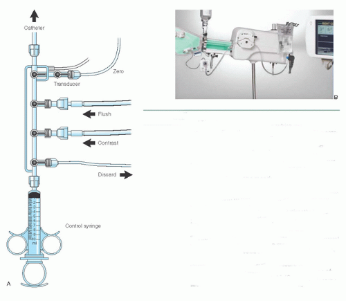 Figure 15.3 A. Four-port coronary manifold. This manifold provides a closed system with which blood can be withdrawn from the catheter and discarded. The catheter can be filled with either flush solution or contrast medium, and the catheter pressure can be observed, all under the control of a series of stopcocks. The fourth port is connected to an empty plastic bag and is used as a discard port (for blood from the double flush, air bubbles) so that the syringe need not be disconnected from the manifold at any time during the procedure. As an alternative, a discard/flush system can allow attaching the flush solution and the discard system to the same port, thus leaving one port available for infusion of drugs or for blood sampling. Attachment of the transducer directly to the manifold allows optimum pressure waveform fidelity (see Chapter 10), and the fluid-filled reference line allows zeroing of the transducer to midchest level. B. The Bracco Acist device consists of a contrast-filled power injector, controlled by a sterile pneumatic actuator to deliver contrast in amounts and rates up to the limits preprogrammed on the digital panel. A power flushing system and a pressure transducer are also included, duplicating many of the functions of the traditional four-port manifold. (Courtesy of ACIST Medical Systems, Inc. Eden Prairie, MN.) |
Another approach to evaluating such ostial lesions is to perform a nonselective injection into the sinus of Valsalva in an appropriate view (that displays the ostium of the vessel in question with no overlap by the sinus of Valsalva). Or the standard end-hole diagnostic catheter may be exchanged for an end- and side-hole angioplasty guiding catheter to overcome damping by preserving partial antegrade flow into the side holes, through the lumen of the catheter, and into the coronary artery, even though the catheter tip may be obstructing entry of blood into the ostium itself (see discussion of cannulation of the right coronary ostium, below). Vigorous injection despite a damped or ventricularized pressure waveform should be avoided, however, since it predisposes to ventricular fibrillation or dissection of the proximal coronary artery with major ischemic sequelae. Such a dissection is detected by tracking of contrast down the vessel over the course of the injection and failure of contrast to clear on fluoroscopy after the injection is terminated (Figure 15.5). Prompt repair by catheter-based intervention or bypass surgery should be considered if creation of such a dye stain is associated with impeded antegrade coronary flow and signs of myocardial ischemia.
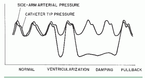 Figure 15.4 Pressure tracings as recorded during coronary angiography. Except for its earlier phase and slightly lower systolic pressure, catheter tip pressure should resemble the pressure waveform simultaneously monitored by way of the femoral side-arm sheath or other arterial monitor (e.g., radial artery). In the presence of an ostial stenosis or an unfavorable catheter position against the vessel wall, the waveform shows either ventricularization (in which systolic pressure is preserved but diastolic pressure is reduced) or frank damping (in which both systolic and diastolic pressures are reduced). In either case, the best approach is to withdraw the catheter immediately until the waveform returns to normal and to attempt to define the cause of the problem by nonselective injections in the sinus of Valsalva. Alternatively, a catheter equipped with side holes near the tip may be used to provide ongoing coronary perfusion. |
Cannulation of the Left Coronary Ostium
Engagement of the left coronary ostium is usually quite easy with the Judkins technique. As Judkins himself has stated, “No points are earned for coronary catheterization—the catheters know where to go if not thwarted by the operator.”25 If a left Judkins catheter with a 4-cm curve (commonly referred to as a JL4) is simply allowed to remain en face as it is advanced down into the aortic root, it will engage the left coronary ostium without further manipulation in 80% to 90% of patients (Figure 15.6). Engagement should take place with the arm of the catheter traversing the ascending aorta at an angle of approximately 45°, the tip of the catheter in a more or less horizontal orientation, and with no change in the pressure waveform recorded from the catheter tip.
In patients with a widened aortic root owing to aortic valve disease or long-standing hypertension, the 4-cm left Judkins curve may be too short to allow successful engagement: The catheter arm may lie nearly horizontally across the aortic root with the tip pointing vertically against the roof of the left main artery, or the catheter may even refold into its packaged shape during advancement into the aortic root (Figure 15.6D). In this case, a left Judkins catheter with a larger (JL4.5, JL5, or even JL6) curve should be selected. In the long run, changing to a larger catheter under these circumstances may end up saving time as compared with trying to make an unsuitable catheter work.
In the occasional patient with a short or narrow aortic root (usually a younger female, particularly if of short stature), even the 4-cm Judkins curve may be too long. When brought down into the aortic root, the catheter arm may lie nearly vertically with the tip pointing downward below the left coronary ostium. The left ostium may still be engaged despite this somewhat unfavorable situation by pushing the catheter down into the left sinus of Valsalva for approximately 10 seconds to tighten the tip angle and then withdrawing the catheter slowly. Having the patient take a deep breath during this maneuver also helps by pulling the heart into a more vertical position to assist in engagement of the left ostium. The most satisfactory approach, however, is to exchange for a JL3.5 catheter with a shorter curve.
On rare occasions, the left coronary ostium lies out of plane (typically high and posterior), as seen in the right anterior oblique (RAO) projection where the ostium is seen to be posterior to the catheter tip. In this case, limited counterclockwise rotation of the left Judkins catheter may help orient the catheter’s tip posteriorly and facilitate engagement. Too much rotation of this catheter, however, may result in a refolded catheter that requires guidewire reinsertion to straighten. In that case, it may be helpful to step up to the next larger Judkins curve. Alternately, some operators prefer to switch to a left Amplatz shape (Figure 15.2; available in progressively larger curves—1, 2, 3, 4). Amplatz catheters26 are more tolerant of rotational maneuvering and allow easy engagement of left coronary ostia that lie out of the conventional Judkins plane, as well as subselective engagement of the left anterior descending and circumflex coronary arteries in patients with short left main coronary segments or separate left coronary ostia. The left Amplatz is advanced around the arch oriented toward the left coronary ostium (Figure 15.7). The tip of the catheter usually comes to rest in the sinus of Valsalva below the coronary ostium. As the catheter is advanced farther, however, the Amplatz shape causes the tip of the catheter to ride up the wall of the sinus until it engages the ostium. At that point, slight withdrawal of the catheter causes deeper engagement of the coronary ostium, whereas further slight advancement causes paradoxic retraction of the catheter tip.
Cannulation of the Right Coronary Ostium
The Judkins technique for engaging the right coronary ostium requires slightly more catheter manipulation than required for cannulation of the left coronary ostium.1,25 After being flushed and filled with contrast in the descending aorta (with the catheter tip directed anteriorly to avoid injection into the intercostal arteries), the right Judkins catheter with a 4-cm curve (JR4) is brought around the aortic arch with the tip facing inward until it comes to lie against the right side of the aortic root with its tip aimed toward the left coronary ostium (Figure 15.6). In a left anterior oblique (LAO) projection, the operator slowly and carefully rotates the catheter clockwise by nearly 180° to engage the right coronary artery. The tip of the right Judkins catheter tends to drop more deeply into the aortic root when the catheter is rotated, as the tertiary curve of the right Judkins shape aligns with the top of the aortic arch. To compensate for this effect, the operator must either begin the rotational maneuver with the tip 2 to 3 cm above the coronary ostium or withdraw the catheter slowly during rotation. Care must be taken to avoid over-rotation of the catheter, which tends to cause the catheter tip to engage too deeply into the right coronary artery. To avoid this common technical error, the operator should be prepared to apply a small amount of counterclockwise torque immediately as the tip of the catheter enters the ostium. Catheters with smaller (3.5 cm) or larger (5 or 6 cm) Judkins curves or right Amplatz catheters (AR1 or AR2) may be of value if aortic root configuration and proximal right coronary anatomy make engagement difficult.
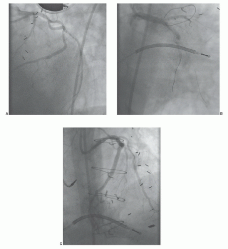 Figure 15.5 Guide catheter-induced coronary dissection and treatment with stent placement. Panel A displays a cranial left anterior oblique image showing the aggressive selective cannulation of the left circumflex coronary artery with an extra back-up catheter. Panel B shows an occlusive dissection and contrast staining in the left circumflex in right anterior oblique. Note that the wire position was preserved throughout the case. Panel C shows the final result with complete restoration of flow after stent placement. (Reproduced with permission from: Cohen MG, Rossi JS. Coronary dissection, side branch occlusion and abrupt closure. In Moscucci M, ed. Complications of Cardiovascular Procedures: Risk Factors, Management and Bailout Techniques. Lippincott Williams & Wilkins; 2011.) |
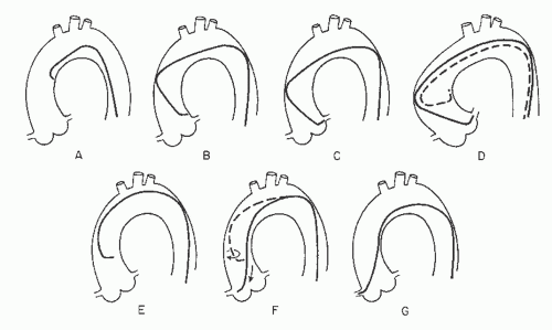 Figure 15.6 Judkins technique for catheterization of the left and right coronary arteries as viewed in the left anterior oblique (LAO) projection. In a patient with a normal-size aortic arch, simple advancement of the JL4 catheter leads to intubation of the left coronary ostium (A-C). In a patient with an enlarged aortic root (D), the arm of the JL4 may be too short, causing the catheter tip to point upward or even flip back into its packaged shape (dotted catheter). A catheter with an appropriately longer arm (a JL5 or JL6) is required. To catheterize the right coronary ostium, the right Judkins catheter is advanced around the aortic arch with its tip directed leftward, as viewed in the LAO projection, until it reaches a position 2 to 3 cm above the level of the left coronary ostium (E). Clockwise rotation causes the catheter tip to drop into the aortic root and point anteriorly (F). Slight further rotation causes the catheter tip to enter the right coronary ostium (G). |
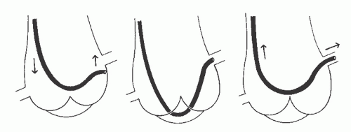 Figure 15.7 Catheterization of the left coronary ostium with an Amplatz catheter. The catheter should be advanced into the ascending aorta with its tip pointing downward so that the terminal catheter configuration resembles a diving duck. As the Amplatz catheter is advanced into the left sinus of Valsalva, its tip initially lies below the left coronary ostium (left). Further advancement causes the tip to ride up the aortic wall and enter the ostium (center). Slight withdrawal of the catheter causes the tip to seat more deeply in the ostium (right). |
Sometimes, the right coronary ostium lies high and anterior above the commissure of the left and right aortic valve leaflets rather than in the middle of the right sinus. If it had not been possible to engage the right coronary with the approach described above, a nonselective injection should be performed into the right sinus of Valsalva. This will show the high-anterior origin and trigger a change to a left Amplatz (either AL0.75 or AL1) as required to make contact with the aortic wall at that ostium location.
Damping and ventricularization are far more common in the right coronary artery than in the left. The cause may be (a) the generally smaller caliber of the vessel (particularly in nondominant vessels; see below), (b) ostial spasm around the catheter tip, (c) selective engagement of the conus branch, or (d) true ostial stenosis. These problems in right coronary engagement can usually be elucidated by nonselective injections into the right sinus of Valsalva or cautious injections in the damped position with immediate postinjection withdrawal of the catheter. As mentioned above, a 6F or 7F guiding catheter with side holes near the tip may be used to allow uninterrupted coronary perfusion between contrast injections, if necessitated by true ostial or proximal right coronary disease.
Cannulation of Saphenous Vein and Arterial Grafts
Despite the high initial rate of anginal relief following bypass surgery, 3% to 12% of saphenous vein grafts occlude within the first month. Additional veins occlude between 1 month and 1 year after surgery owing to exaggerated neointimal hyperplasia. By far the dominant failure mode of saphenous vein graft failure beyond 1 year, however, is diffuse graft atherosclerosis, which accounts for a 50% graft closure rate by 7 years.27 Free arterial grafts (free radial or free internal mammary) are sometimes used instead of saphenous vein grafts, and these have an intermediate long-term patency between that of saphenous vein grafts and pedicled internal mammary grafts (see below). An increasing number of patients thus develop recurrent angina after prior bypass surgery owing to vein graft or progressive native vessel disease, and these patients account for an increasing number of diagnostic procedures.
The proximal anastomosis of a vein graft or free arterial graft is usually placed on the right or left anterior aortic surface, several centimeters above the sinuses of Valsalva. Because many surgeons still resist the practice of placing radiopaque markers on the proximal graft,28 the operator must generally rely on the surgeon’s operative report or diagram, as well as on knowledge of usual surgical practice in his/her own institution. The operative report always should be obtained before elective angiography on any patient with prior bypass surgery, but is absolutely essential for patients who underwent their operation at another medical center (where local preference may include practices like proximal anastomosis to the right posterior surface of the aorta [see below] or even proximal anastomosis to the descending aorta in patients with aortic root disease). It may thus be quite frustrating to embark on coronary angiography in a patient with prior bypass surgery without a detailed graft map, operative note, or prior detailed catheterization report/films in hand. In addition, searching for proximal anastomosis while not knowing the number of anastomosis or their location increases the risk of stroke and increases the total amount of contrast media needed to perform the procedure, thus also increasing the risk of contrast-induced nephropathy.
If no markers have been provided, the catheter tip should be oriented against the appropriate aortic wall and slowly advanced and then withdrawn until its tip catches in a graft ostium. The graft is injected in multiple projections that show its origin, shaft, distal anastomosis, and the native vessels beyond the anastomosis. This process must then be repeated until all graft sites have been identified. Grafts should not be written off as occluded unless a clear stump is demonstrated. If the myocardial territory supplied by a graft assumed to be occluded is still contracting, and there is no evident native or collateral blood supply to that territory, there may be a missed graft—the myocardium cannot function without a visible means of support! In that case, it may be valuable to perform an aortogram in an appropriate view to try to demonstrate flow in and locate the origin of such a missed graft. The emergence of effective therapies for focal lesions in vein grafts has placed a premium on being able to find and fix such diseased grafts before they occlude (Figure 15.8; see Chapters 29, 31, and 33).
Left Coronary Artery Grafts
Most commonly, grafts to the left coronary arise from the left anterior surface of the aorta, with grafts to the circumflex system usually placed somewhat higher on the aorta than those to the left anterior descending or diagonal branches. Alternatively, some surgeons prefer to route grafts to the circumflex through the transverse sinus behind the heart, in which case the circumflex graft may originate from the posterior surface of the aorta. Our preferred view for engagement of
left coronary artery grafts is the right anterior oblique view, with the tip of the catheter pointing anteriorly (to the right of the angiographic view). Alternatively, the left anterior oblique view can also be used.
left coronary artery grafts is the right anterior oblique view, with the tip of the catheter pointing anteriorly (to the right of the angiographic view). Alternatively, the left anterior oblique view can also be used.
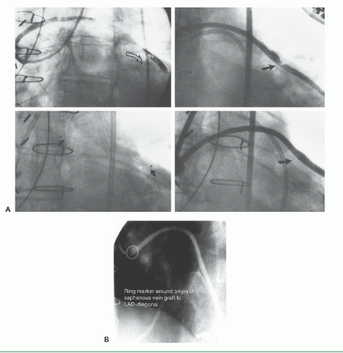 Figure 15.8 A. Sample of saphenous vein graft angiography, showing an occluded graft to the circumflex, filled with thrombus (top left, open arrow). A drug-infusion catheter (Tracker, Target Therapeutics) was placed (bottom left, curved arrow) and used to administer Urokinase (50,000 IU/hour) overnight. The following morning (top right), the thrombus had been dissolved, revealing the underlying ulcerated culprit lesion. This was treated with a single Palmaz-Schatz coronary stent (bottom right), reestablishing full patency. B. Saphenous vein graft with its origin localized by a ring marker implanted at the time of surgery. |
Right Coronary Artery Grafts
Grafts to the right coronary (or the distal portions of a dominant circumflex) usually originate from the right anterior surface of the aorta, above and somewhat behind the plane of the native right coronary ostium. We generally use a right Judkins (JR4) or an Amplatz (AL1) catheter to engage anterior (i.e., left) coronary grafts. Special left coronary bypass, internal mammary, or hockey stick catheters may be required for left grafts that originate with an upward trajectory (Figure 15.9). For downward-pointing right coronary grafts, we prefer a soft catheter with no primary curve (a multipurpose, Wexler, or JR3.5 short-tip catheter), which provides
better alignment with the proximal portion of the graft and thus better opacification. The Wexler catheter can also be used for grafts originating from the left or posterior surface of the aorta. Since its tip remains in contact with the aortic wall, the shaft of this catheter can be rotated or the tip can be flexed to bring it into alignment with the proximal graft once the ostium has been engaged. Our preferred view for engagement of right coronary artery grafts is the left anterior oblique view, with the tip of the catheter pointing downward and toward the right of the aortic wall (left in the angiographic view).
better alignment with the proximal portion of the graft and thus better opacification. The Wexler catheter can also be used for grafts originating from the left or posterior surface of the aorta. Since its tip remains in contact with the aortic wall, the shaft of this catheter can be rotated or the tip can be flexed to bring it into alignment with the proximal graft once the ostium has been engaged. Our preferred view for engagement of right coronary artery grafts is the left anterior oblique view, with the tip of the catheter pointing downward and toward the right of the aortic wall (left in the angiographic view).
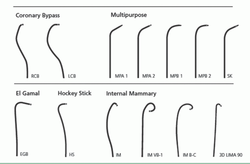 Figure 15.9 Catheters used for bypass graft angiography. Although the right Judkins or Amplatz catheters can be used for many anterior take-off vein grafts, the catheters shown here may be useful. Top, left to right. Right coronary bypass, left coronary bypass, multipurpose “A” 1 and 2, multipurpose “B” 1 and 2, and multiple SK. Bottom, left to right. El Gamal, hockey stick, and left internal mammary artery. |
Internal Mammary Artery Cannulation
Based on their superior demonstrated 10-year patency, the pedicled left and right internal mammary arteries (IMAs, also known as internal thoracic arteries [ITAs]) have become the conduits of choice. The proximal end of this graft remains attached to the subclavian artery (supplying the nutritional needs of the graft itself), as the vessel is freed up from its lower sternal attachments and anastomosed to the target coronary artery (usually the left anterior descending). More than 90% of current elective bypass procedures involve placement of at least one internal mammary graft.
Successful cannulation29 requires knowledge of the left subclavian and brachiocephalic trunk as well as the right subclavian arteries, as shown in Figure 15.10A. It is also important to understand some of the common anatomic variants in the internal mammary artery, including more proximal origin in the vertical portion of the subclavian, or origin as a common vessel with the thyrocervical trunk.
Although uncommon, these grafts can develop significant lesions, making it important to evaluate such grafts during any postbypass catheterization. In patients with early recurrence of angina (within the first 6 months after surgery), most commonly the lesion is located at the distal mammary-coronary anastomosis. It occurs usually owing to local intimal hyperplasia rather than atherosclerosis and responds well to balloon angioplasty. Flow-limiting kinks may also be present in the midgraft, and ostial lesions at the origin of the internal mammary from the subclavian may also occur. In patients years postbypass, significant lesions may develop in the native coronary artery beyond the internal mammary touchdown. In addition to establishing the patency of the internal mammary itself, it may also be important to look for large nonligated side branches that may divert flow from the coronary circulation and occlusion of which (in the occasional patient) may be required for angina relief.30 It is also important to look for stenoses in the subclavian artery before the take-off of the internal mammary, which may compromise the inflow to the graft and thereby cause myocardial ischemia (Figure 15.11). Such lesions may require construction of a carotid-to-subclavian graft, or more commonly stent placement,31
to restore normal flow to the internal mammary and vertebral branches of the subclavian artery (see Chapters 19 and 34).
to restore normal flow to the internal mammary and vertebral branches of the subclavian artery (see Chapters 19 and 34).
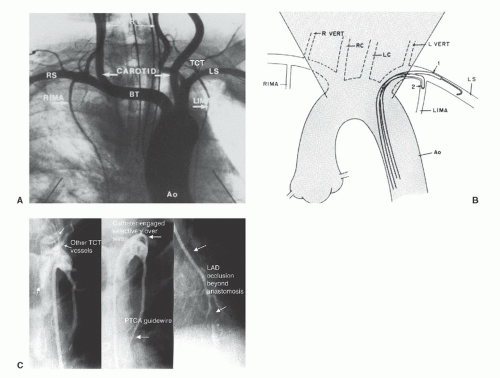 Figure 15.10 Internal mammary angiography. A. Aortic arch injection shows the left internal mammary artery (LIMA) originating from the left subclavian (LS), just opposite the thyrocervical trunk (TCT) and distal to the right vertebral artery (VERT). The right internal mammary artery (RIMA) originates from the right subclavian (RS) just distal to the bifurcation of the right carotid from the brachiocephalic trunk (BT). B. Schematic diagram shows the corresponding arch vessel origins. Note that the left subclavian originates just inside the patient’s leftmost edge of the wedge-shaped shadow cast by the upper-mediastinal structures in the left anterior oblique projection. Catheter manipulation in this projection facilitates advancement of a guidewire into the LS (step 1), facilitating selective cannulation of the LIMA during catheter withdrawal and slight counterclockwise rotation (step 2, see text). C. Variant in which internal mammary originates in common with thyrocervical trunk, resulting in poor opacification. An angioplasty guide wire was placed down the internal mammary through a 6F diagnostic catheter and used to advance the tip of the diagnostic catheter selectively down the IMA. From that position, sufficient opacification was obtained to demonstrate occlusion of the distal left anterior descending (LAD) beyond the anastomosis as the cause of the patient’s recurrent angina. |
Although mammary grafts can be studied easily from the ipsilateral brachial approach, we prefer the femoral approach using a soft-tip preformed internal mammary catheter, which resembles a right Judkins catheter except for a tighter primary curve. This used to be a time-consuming (up to 20 minutes for some operators) process, but the required time can be reduced to less than 3 minutes by adoption of a systematic strategy29 (see Figure 15.10B). In the LAO projection, cannulation of the left internal mammary artery begins by advancement of this catheter into the aortic arch until it
lies just inside the left edge of the wedgelike density formed by the shadow of the upper mediastinum against the lung fields. With 1 to 2 cm of J guidewire protruding from its tip, the mammary catheter is rotated counterclockwise and slowly pulled back until it falls into the subclavian artery origin. From there, the wire can be advanced well out into the axillary artery. The mammary catheter is then advanced over the wire, into the midsubclavian, where the guidewire is then removed and the catheter is flushed and filled with contrast. A low-osmolar contrast agent should be used to avoid causing CNS toxicity by reflux of hyperosmolar ionic contrast up the vertebral arteries. Switching to the straight AP projection, the catheter is rotated counterclockwise slightly (to make the tip point slightly anteriorly) as it is withdrawn slowly until the internal mammary is engaged. Intermittent gentle puffs of contrast will help localize the mammary origin during this withdrawal. Great care should be taken to avoid catheter tip trauma/dissection of the relatively delicate mammary vessel.
lies just inside the left edge of the wedgelike density formed by the shadow of the upper mediastinum against the lung fields. With 1 to 2 cm of J guidewire protruding from its tip, the mammary catheter is rotated counterclockwise and slowly pulled back until it falls into the subclavian artery origin. From there, the wire can be advanced well out into the axillary artery. The mammary catheter is then advanced over the wire, into the midsubclavian, where the guidewire is then removed and the catheter is flushed and filled with contrast. A low-osmolar contrast agent should be used to avoid causing CNS toxicity by reflux of hyperosmolar ionic contrast up the vertebral arteries. Switching to the straight AP projection, the catheter is rotated counterclockwise slightly (to make the tip point slightly anteriorly) as it is withdrawn slowly until the internal mammary is engaged. Intermittent gentle puffs of contrast will help localize the mammary origin during this withdrawal. Great care should be taken to avoid catheter tip trauma/dissection of the relatively delicate mammary vessel.
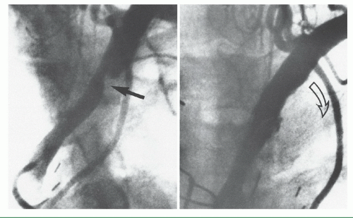 Figure 15.11 Left subclavian stenosis, in a patient with recurrent angina, in the distribution of the otherwise patent left internal mammary artery (left), treated by stenting (right). |
If selective cannulation is difficult because of tortuosity or anatomic variations, a variety of superselective or nonselective techniques can be used to permit angiographic evaluation. Nonselective injections into the subclavian will generally allow adequate opacification to see whether the internal mammary is open, but generally not to provide detailed information about the distal native vessel. Inflation of a blood pressure cuff on the ipsilateral arm may help reduce runoff through the axillary artery and improve opacification of the internal mammary in cases where selective cannulation is difficult. When selective cannulation proves difficult, a Y connector can be attached to the hub of the diagnostic internal mammary catheter and a 0.014-inch soft-tipped coronary angioplasty guidewire can be advanced into the mammary to serve as a support for catheter advancement.
Cannulation of the right internal mammary artery may be slightly more difficult because of the need to avoid the right carotid before entering the right subclavian itself. Again in the LAO projection, the upper mediastinal wedge is identified. The mammary catheter with protruding J wire is taken to the right edge of this shadow and rotated counterclockwise until it falls into the brachiocephalic trunk. The wire is then advanced toward the right subclavian artery. Predilection for the wire to advance into the right carotid artery may require removing the guidewire and performing a nonselective contrast injection in the brachiocephalic trunk to identify the origin of the subclavian branch. The RAO-caudal projection often gives the best spatial resolution of the right carotid and right subclavian origins, after which a steerable Wholey guidewire (Mallinckrodt) can be used to cannulate the subclavian. Once the wire is firmly out of the subclavian artery, the mammary catheter is advanced as described above. For cannulation of the right internal mammary artery, however, the catheter is rotated slightly clockwise during withdrawal to point its tip anteriorly.
Gastroepiploic Graft Cannulation
Taken together, the left and right internal mammary arteries can be used to revascularize most lesions in the left anterior descending, proximal circumflex, and proximal right coronary arteries. Even with sequential distal anastomoses,
however, the fact that there are only two internal mammary arteries means that most revascularization procedures still suffer the long-term limitations associated with the use of saphenous veins. Free segments of radial artery have also been used as bypass conduits, either from the ascending aorta (like a saphenous vein) or from the descending thoracic aorta32 in some patients undergoing repeat bypass surgery. Although the radial artery may have slight benefit over the saphenous vein, it is prone to spasm in the early postop period and does not match the long-term patency record of the internal mammary artery (because it does not retain its blood supply and innervation when used as a free graft). The effort to perform all-arterial bypass has brought back the right gastroepiploic artery (as an arterial pedicle graft) for anastomosis to the posterior descending or other vessels on the inferior surface of the heart.33 The right gastroepiploic normally supplies most of the greater curvature of the stomach, but can be dissected free from that organ and tunneled through the diaphragm to reach the inferior wall of the heart. Angiography of this vessel is possible using standard visceral angiographic catheters (e.g., Cobra) designed to enter visceral arteries such as the celiac axis.34 From there, the catheter can be advanced into the common hepatic (as opposed to the splenic) artery and then turned downward into the gastroduodenal artery (Figure 15.12). A 0.025-inch Glidewire (Terumo) can then be used to cannulate the right gastroepiploic (as opposed to the superior pancreatoduodenal artery) if more selective injection is desired.
however, the fact that there are only two internal mammary arteries means that most revascularization procedures still suffer the long-term limitations associated with the use of saphenous veins. Free segments of radial artery have also been used as bypass conduits, either from the ascending aorta (like a saphenous vein) or from the descending thoracic aorta32 in some patients undergoing repeat bypass surgery. Although the radial artery may have slight benefit over the saphenous vein, it is prone to spasm in the early postop period and does not match the long-term patency record of the internal mammary artery (because it does not retain its blood supply and innervation when used as a free graft). The effort to perform all-arterial bypass has brought back the right gastroepiploic artery (as an arterial pedicle graft) for anastomosis to the posterior descending or other vessels on the inferior surface of the heart.33 The right gastroepiploic normally supplies most of the greater curvature of the stomach, but can be dissected free from that organ and tunneled through the diaphragm to reach the inferior wall of the heart. Angiography of this vessel is possible using standard visceral angiographic catheters (e.g., Cobra) designed to enter visceral arteries such as the celiac axis.34 From there, the catheter can be advanced into the common hepatic (as opposed to the splenic) artery and then turned downward into the gastroduodenal artery (Figure 15.12). A 0.025-inch Glidewire (Terumo) can then be used to cannulate the right gastroepiploic (as opposed to the superior pancreatoduodenal artery) if more selective injection is desired.
THE BRACHIAL OR RADIAL APPROACH
The technique of brachial artery cutdown was the first approach used for selective coronary angiography, as described in Chapter 8. Dr. F. Mason Sones, Jr., designed the original catheter for this approach—a thin-walled radiopaque woven Dacron catheter with a 2.67-mm (8F) shaft diameter,1,35 tapering to 5F external diameter at a point 5 cm from its tip. In addition to the open tip, current models include side holes that are arranged in opposed pairs within 7 mm of the distal end. As Sones stated, this provides a “flexible finger” that may be curved upward into the coronary orifices by pressure of the more rigid shaft against the aortic valve cusps. This enables the Sones catheter to be used for cannulation of both the left and right coronary arteries, as well as for entry into the left ventricle for ventriculography. The standard Sones catheter is available in lengths of 80, 100, and 125 cm and 6F to 8F diameters. Most operators now use a different Sones-type coronary catheter constructed of polyurethane and made by Cordis Corporation. This catheter traverses a tortuous subclavian system with much greater facility and smoothness than does the woven Dacron catheter, and its enhanced torque control and reduced coefficient of friction ease engagement of the coronary ostia. See Figure 15.2 for a variety of preshaped coronary catheters, which are also effective from the brachial approach.36 In general, similar techniques as described above for the femoral approach apply for use of standard Judkins and Amplatz shapes from the left brachial or radial arteries. From the right brachial or radial arteries, smaller left Judkins curves or special catheter shapes are preferable (see Chapters 7 and 8).
When the Sones method is used from the right arm, catheter tip pressure should be monitored continuously once the catheter enters the brachial artery. Further passage of the catheter into the subclavian and brachiocephalic arteries should be accomplished under both pressure monitoring and fluoroscopic visualization. Occasionally, it may be difficult to pass the catheter from the subclavian artery to the aortic arch, but a simple maneuver by the patient—such as a deep inspiration, shrugging the shoulders, or turning the head to the left—often facilitates passage of the catheter into the ascending aorta. If passage of the catheter from the subclavian artery to the ascending aorta is not accomplished immediately and with complete ease, the operator should stop catheter manipulation and use a soft J-tipped 0.035-inch guidewire. Once the catheter is in the ascending aorta, the guidewire is removed and the catheter is aspirated, flushed, and reconnected to the rotating adapter of the manifold, either directly or by a short length of large-bore flexible connecting tubing.
With the Sones technique, selective engagement of the left coronary artery is accomplished as follows. In a left anterior oblique projection, the sinus of Valsalva containing the ostium of the left coronary artery lies to the left, and the sinus containing the ostium of the right coronary artery lies to the right. The noncoronary sinus lies posteriorly. The operator advances the catheter to the aortic valve and then continues to advance the catheter until its tip bends cephalad and points toward the left coronary ostium. When the catheter is properly positioned with its tip bent cephalad, slightly advancing or rotating the catheter usually results in selective engagement of the left coronary ostium, which is verified by a small injection of radiographic contrast agent. Occasionally, a deep breath taken by the patient will facilitate this selective engagement. Our usual approach, as described in Chapter 8 and illustrated in the upper left panel of Figure 15.13, involves forming a smooth shallow loop and gradually inching up to the ostium from below. If the distal 2 to 3 mm of the catheter tip bends downward during this inching-up process, the tip may enter the left coronary artery, giving a cobra head appearance (see Figure 15.13, top right) similar to that achieved with the left Amplatz catheter (see Figure 15.7). For the high take-off left coronary ostium, the catheter may have the appearance (as in Figure 15.13, bottom) in which the catheter tip is lying across the ostium at right angles to the course of the left main coronary artery. During contrast injection in this instance, coronary blood flow generally carries the contrast agent down the vessel, giving good opacification of the entire left coronary artery. Once the catheter tip has engaged the coronary ostium and no damping of pressure
from the catheter tip is observed, cineangiography may be performed with selective injection of radiopaque material in a variety of views, as described below.
from the catheter tip is observed, cineangiography may be performed with selective injection of radiopaque material in a variety of views, as described below.
Stay updated, free articles. Join our Telegram channel

Full access? Get Clinical Tree


