Fig. 3.1
Chest radiographs in two projections (left panel: left anterior oblique; right panel: right anterior oblique) demonstrating placement of four bipolar electrode pair electrodes; one each in the high right atrium (HRA), coronary sinus (CS), His bundle region (His), and right ventricular apex (RV apex); the last two sites are recorded through a single catheter. The mapping catheter (Abl/Map) is in the mid septal region in the triangle of Koch. The CS catheter in the right anterior oblique projection is superimposed on and obscured by the His catheter
Fig. 3.2
Baseline electrograms from EPS. From top to bottom: surface ECG Leads I, II, aVF; HRA, His electrograms proximal (9–10) to distal (3, 4), CS proximal (9, 10) to distal (1, 2), RV apex, surface V1 and V6. Measured intervals as displayed are sinus cycle length 740 ms, AH interval 75 ms, HV interval 50 ms, QRS duration 66 ms. HRA high right atrium, CS coronary sinus, RV right ventricle
Unipolar electrograms display the electrical activation relative to a single electrode using a distant “indifferent” electrode (Wilson’s central terminal or a remote electrode) as the opposite pole. The unipolar electrogram provides information on the local activation based on signal polarity, but is disadvantaged because they contain additional far-field signal. Bipolar electrograms are more commonly used. They are recorded between two adjacent electrodes (inter-electrode distance is 1–5 mm), thereby minimizing much of the far-field signal and providing more precise information on the timing of local activation. Thus, by virtue of this proximity effect, the electrical activity of localized areas of the atrial and ventricular myocardium, and the His bundle potential can be recorded with intracardiac electrode pairs.
Sedation/Anesthesia
Pediatric patients and most adult patients will require sedation or general anesthesia for a typical catheter ablation procedure due to case duration. The preference for general anesthesia or moderate to deep sedation tends to be center or substrate dependent. We utilize general anesthesia almost exclusively except for substrates which may be repressed by general anesthesia. Modifications in the procedural regulations over the past decade have dictated at many centers that a dedicated physician be in charge of patient sedation. For our own center, this has been the pediatric anesthesia service. General anesthesia allows for complete control of patient movements during ablation but requires intubation and may result in post-procedure nausea and longer recovery. General anesthesia may also act to suppress certain arrhythmia substrates—focal atrial tachycardia and atrioventricular reentrant tachycardia AVNRT due to effects of gas anesthesia on electrophysiology. For these reasons, moderate sedation may be preferable in some circumstances.
Access
The Electrophysiology Study (EPS) begins with access to the intravascular space. The chosen sites of access are operator dependent. Access is obtained using modified Seldinger technique to place valved sheaths into the vein allowing easy catheter exchange. In our laboratory, with rare exception, all access is via the femoral veins; typically, two sites on each side to accommodate three diagnostic and one ablation catheter. Many labs, however, routinely utilize jugular venous access typically for coronary sinus catheter placement. For those patients with limited femoral access, not uncommon in congenital heart disease patients, an alternative access point is a transhepatic sheath (Fig. 3.3). This typically will require interventional cardiologist involvement as coil closure of the transhepatic tract is recommended to decrease the risk of bleeding complications.
Fig. 3.3
Passage of transhepatic sheath and catheter through the liver and into the right atrium and superior vena cava in an 8-kg infant
Arterial cannulation for monitoring of systemic blood pressure can be used selectively. For most patients with supraventricular tachycardia, monitoring of the blood pressure by sphygmomanometer is sufficient, avoiding the need for an intra-arterial cannula. In patients with poor ventricular function, suspected ventricular arrhythmias, infants (≤15 kg), or patients with adult congenital heart disease, the use of direct intra-arterial blood pressure monitoring may be desirable.
Diagnostic Catheters and Placement
A variety of specially designed diagnostic catheters exist to record electrograms from varied or specific locations within the heart (Fig. 3.4). Positions are strategically chosen to allow for differentiation of the electrical activation in the heart in order to identify the origin and direction of electrical propagation. The routine sites for a typical EPS include the right atrium (RA), right ventricle (RV), coronary sinus (CS), and bundle of His (Fig. 3.2). A bipolar or quadripolar catheter suffices for the RA and RV sites. The CS catheter is usually an octapolar or decapolar catheter which allows for differentiation of the timing of left atrial activation from the CS os (proximal) to the distal CS along the lateral rim of the mitral valve annulus. The His bundle potential can be recorded by placing a catheter across the tricuspid valve annulus at the superior septum. Specially formed catheters (Josephson curve or St. Jude CRd2) may improve stability and quality of the recorded His potential. In our own lab, a combined His/RV catheter (Fig. 3.4) is preferred to decrease the number of access sites. This catheter has two distal electrodes placed in the RV and an array of proximal electrodes which sit at the His bundle. We primarily use deflectable His/RV catheters with a 30 mm His–RV separation or a 50 mm His–RV separation.
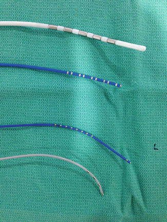
Fig. 3.4
Diagnostic catheters: Several types of diagnostic catheters used in an electrophysiology study. From top to bottom: Pentapolar esophageal catheter (top catheter). Decapolar deflectable catheter with 2–5–2 mm spacing (6Fr, second catheter). Deflectable decapolar His/RV combination catheter with distal bipolar pair of electrodes and a proximal array for His recording (third catheter). Josephson curve quadripolar catheter for multipurpose use (bottom catheter)
Additionally, a quadripolar or pentapolar esophageal catheter (Fig. 3.4) may be added to provide an atrial pacing and recording site while potentially decreased the need for additional venous access. The esophageal catheter also functions well as a reference site for activation mapping as its position tends to be stable and easily confirmable with fluoroscopy if needed; in the infant, it can serve to deliver atrial extrastimulation.
Catheter Navigation
Visualization of the diagnostic and ablation catheters has traditionally been with fluoroscopy. Evolution of computerized 3D electro-anatomic mapping systems over the past decade has led to its nearly exclusive method for catheter navigation in our own and many pediatric laboratories across the country (also see Chap. 23).
The most commonly used systems are Ensite (St. Jude Inc., St. Paul, MN) (Fig. 3.5) and CARTO (Biosense-Webster, Diamond-Bar, CA) (Fig. 3.6). We currently use both Ensite Velocity and CARTO3 with approximately equal use between the two systems. Choice of system is primarily by attending preference and secondarily by arrhythmia substrate or patient characteristics. The Ensite system allows for visualization and placement of all diagnostic catheters prior to choosing an ablation catheter. Any radiofrequency or cryocatheter is compatible with the Ensite system. The CARTO system requires a proprietary catheter to create an endocardial geometry prior to additional catheter placement. Proprietary radiofrequency catheters must be used for ablation, though cryocatheters can be used with minor connection adjustments.
Fig. 3.5
Monitor image of Ensite Velocity electroanatomic mapping system as used for catheter navigation in routine electrophysiology study. Left-side is an RAO view as demonstrated by torso in upper screen. Right side is LAO view. Yellow catheter is a decapolar catheter placed in the coronary sinus. Green catheter is the His array of a His/RV combo catheter. RV apex electrodes are in red in the LAO view only. White catheter is a quadripolar high right atrial catheter
Fig. 3.6
Monitor image from CARTO3 electroanatomic mapping system as used for catheter navigation during electrophysiology study. Left–hand panel is RAO view as indicated by “face” position at top of screen. Right-hand panel is LAO view. Aqua catheter is decapolar catheter placed in the coronary sinus. Green catheter in the RAO view is the His array of a His/RV combo catheter. The blue dot in the LAO view was the location of a His potential. The dark blue catheter with purple tip in the LAO view is a radiofrequency catheter positioned to ablate a left lateral accessory pathway
Specific Considerations for Pediatrics and Congenital Heart Disease
The EPS the infant or small child requires special considerations. First, the operator should be experienced in advancing and navigating an electrode catheter through the cardiac chambers of young patients. The operator should be fully informed regarding the clinical course and structural features of concomitant cardiac malformations. Structural congenital heart lesions affect the location of the SA and AV nodes and specialized conduction tissue. Operations for these congenital heart lesions can further alter the electrical properties of the atrial and ventricular myocardium, resulting in complex rhythm disturbances.
The risk of catheter ablation in pediatric patients was shown to carry increased, though not prohibitive, risk in children less than 5 years old or less than 15 kg. The enhanced risk includes difficulty of vascular and intracardiac access, alterations in hemodynamic state, potential perforation and pericardial effusion with tamponade, potential for excessive lesion size (and possible expansion), and injury to the AV node. Between 15 and 35 kg, the risks are diminished and beyond 35–50 kg, the risk of electrophysiologic study is essentially equivalent to that in adult patients.
When considering electrophysiologic study in the small infant or child, the number of catheters, the size of the catheters, and the stiffness of the catheters should be minimized. Because of the variable dimension of the cardiac chambers in different size children, steerable catheters with different shapes and different sized curves are necessary to appropriately accommodate each patient. Adolescents are usually of sufficient size to allow use of catheters and sheaths of the length and caliber of those used in adults. However, smaller children require smaller catheters and sheaths, especially in the diameter of the operator-controlled curve. Typically, for a child 20 kg or less, diagnostic catheters should not exceed 6 French; though 7Fr ablation catheters may occasionally be necessary. For an infant under 10 kg, 4 and 5 French catheters are used including the mapping/ablation catheter; although, again 7Fr RF and cryocatheters may be required for effective ablation. Additionally, the esophageal catheter can be a useful addition to the EPS in a small patient.
Due to the vigorous contractile state and the faster heart rates in small children compared to adults, both during sinus rhythm and tachycardia, catheter stability is at risk. There is always a trade-off between catheter size (and stiffness) and catheter stability. The combined His-RV catheter adds stability to the His catheter since it is, in part, secured by the placement of the catheter tip in the RV apex. Multiple catheters produce artifacts when the electrodes from different catheters strike one another, a confounder increased in the smaller volume of a child’s heart (≤20 kg).
Intracardiac Electrophysiology
The purpose of the electrophysiology study is to assess the basic electrophysiologic properties of the patient’s cardiac conduction system and to determine the mechanisms of the suspected or clinically demonstrated cardiac arrhythmia. The study begins with the measurement of baseline intervals (Table 3.1). The P-A interval denotes the intra-atrial conduction time. The A-H interval assesses the conduction time through the AV node. The H-V interval marks the conduction time through the His-Purkinje system. This interval is fairly constant but does increase slightly from approximately 25 ± 10 to 45 ± 10 ms from infancy to adulthood. An H-V interval greater then 60 ms in the young is abnormal and suggests an abnormality in the His-Purkinje system. It is unusual in the child, even following surgery for congenital heart disease, to have a prolonged H-V interval. Top normal H-V intervals are not uncommon, however, in patients with AV septal defects (AV canal defects) and older postoperative tetralogy of Fallot and ventricular septal defect patients.
Table 3.1
Conduction intervals
Interval | Measurement (normal values) |
|---|---|
P-A | Atrial conduction time—beginning from the earliest P-wave on the ECG to the earliest fast atrial deflection on the low septal right atrial electrogram |
A-H | AV nodal conduction time—from earliest fast atrial deflection on the annular septal right atrial electrogram to the beginning of the His bundle potential recorded on the His bundle electrogram. Varies with heart rate and autonomic tone |
H-V | His-Purkinje conduction time—from beginning of the His bundle potential recorded on the His bundle electrogram to the onset of the surface QRS or earlier ventricular electrogram |
In the past, evaluation of the SA node was a routine part of the EPS, though is now seldom performed. SA node function is tested by measuring the SA node recovery time (SNRT) and corrected SA node recovery time (CSNRT). A fixed train (usually 30 s) of external stimuli is delivered to the atrium. When atrial pacing is terminated, the recovery interval of the SA node is measured (i.e., time from the last pacing stimulus to the first spontaneous signal emerging from the SA node recorded as an atrial electrogram in the catheter that delivered the pacing stimuli). This procedure is performed at a pacing rate of 90, 120, 150, 180, and 286 bpm. The maximal SA node recovery time (SNRT) is that maximal escape interval that follows termination of pacing at any pacing rate. The SNRT can be corrected for the normal spontaneous discharge rate by subtracting the basic cycle length (Fig. 3.7). To truly isolate the intrinsic automaticity of the SA node the autonomic nervous system must be attenuated using atropine and beta-blocker. Its clinical purpose was to evaluate an individual with suspected sick sinus syndrome (Chap. 13); this condition is effectively evaluated by surface ECG recordings such as the Holter 24 h dynamic ECG tracing.
Fig. 3.7
Measurement of sinus node recovery time: Left panel: Atrial pacing at 400 ms (150 bpm). Upon termination of pacing, the normal recovery time of the SA node (P-wave) is 620 ms. Subtracting that interval from the basic sinus interval of this patient of 500 ms, yields a normal Maximal Corrected Sinus Node Recovery Time (MCSNRT) of 120 ms. Right panel: In contrast, cessation of pacing in a 15-year-old patient following the Mustard operation for transposition of the great arteries yields a junctional escape beat with an escape interval of 1,450 ms. Both the escape mechanism and the escape interval are abnormal
Refractory periods are measured using programmed extrastimulation. A drive of 8–10 pacing stimuli are delivered at a constant interval (S1S1) followed by a premature stimulus delivered at a shorter interval (S1S2). This process is reiterated, sequentially shortening the premature beat (S2) until it fails to capture or propagate to the target tissue. This process yields the relative, functional, and effective refractory periods of the tissue in question (Tables 3.2 and 3.3). Because the AV node displays decremental conduction, several specific refractory periods can be measured (Table 3.3, displayed graphically in Fig. 3.8 and with intracardiac tracings in Fig. 3.9).
Table 3.2
Electrophysiologic data in children
Group | <0.5 year | N | 0.05–1 year | N | 1–5 year | N | 5–10 year | N | >10 year | N | |
|---|---|---|---|---|---|---|---|---|---|---|---|
Age | 0.28 | 19 | 0.66 | 18 | 3.1 | 37 | 6.9 | 17 | 16.2 | 21 | |
Range | 0.01–0.18 | 0.52–0.98 | 1.0–4.9 | 5.1–9.9 | 10–25 | ||||||
SCL (x ± SD) | (ms) | 456 ± 50 | 19 | 471 ± 66 | 18 | 547 ± 37 | 37 | 610 ± 83 | 17 | 814 ± 132 | 21 |
Panel A: Conduction intervals (x ± SD) (ms) | |||||||||||
PA | 24 ± 7 | 10 | 22 ± 14 | 12 | 29 ± 15 | 30 | 29 ± 12 | 11 | 29 ± 14 | 13 | |
AH | 72 ± 14 | 11 | 75 ± 14 | 14 | 71 ± 20 | 30 | 75 ± 18 | 12 | 91 ± 21 | 14 | |
HV | 33 ± 9 | 11 < div class='tao-gold-member'>
Only gold members can continue reading. Log In or Register to continue
Stay updated, free articles. Join our Telegram channel
Full access? Get Clinical Tree
 Get Clinical Tree app for offline access

| |||||||||