9 Catheterization of the Cardiac Chambers
Left Heart Catheterization
 Specific Indications
Catheterization of the left ventricle with left ventriculography is an integral part of almost all cardiac catheterizations. Ventriculography can be done either before or after imaging of the coronary arteries. However, many operators start with coronary angiography for two reasons:
1. If catheterization has to be stopped prematurely, ventricular function can be assessed by noninvasive means (echocardiography, MRI).
2. After assessing the coronary status (e.g., with severe three-vessel disease or main stem stenosis) the volume of contrast needed for ventriculography can be better adjusted when the left ventriculogram is performed at the end of the study.
The following findings can be obtained from the left ventriculogram:
 Imaging and quantification of regional and global ventricular function including determination of ejection fraction
 Measurement of end-systolic and end-diastolic volumes with derivation of stroke volume
 Determination of left ventricular wall thickness
 Imaging of ventricular geometry in hypertrophic cardiomyopathy
 Imaging of masses within the left ventricle (thrombi, tumors)
 Demonstration and quantification of mitral regurgitation
 Quantification of regurgitant fraction in aortic regurgitation
 Demonstration and imaging of a ventricular septal defect
Given these potential findings there is a correspondingly wide indication for left ventriculography. Left heart catheterization is also performed to measure left ventricular pressures and for the invasive determination of pressure gradients and valve areas for the aortic valve and mitral valve in the setting of aortic and mitral stenosis, respectively. Furthermore, measuring left ventricular end-diastolic pressure (LVEDP) provides important information for the assessment of diastolic ventricular function.
Indication Restrictions and Contraindications
Not necessarily indicated is a repeat ventriculogram, for example, during a follow-up coronary angiography after PCI, which is performed in some centers (the practice varies across the globe). This is especially true if ventricular function can be well assessed by echocardiography. Also, if there are technical difficulties for ventricular catheterization, for example, severe aortic stenosis, the left ventriculogram may be omitted provided an adequate assessment of ventricular function and severity of the stenosis is possible by echocardiography or cardiac MRI. The same is true for thrombi in the left ventricle.
An absolute contraindication for left ventricular catheterization is in the case of suspected perforation or a contained rupture of the free wall after acute myocardial infarction. Another contraindication for retrograde catheterization of the left ventricle is the presence of mechanical valve prostheses in the aortic position (Björk Shiley, St. Jude). In contrast, bioprostheses may be crossed retrogradely. In the case of florid aortic valve endocarditis, retrograde left heart catheterization is also strictly contraindicated.
It should also be recognized that every ventriculogram is a contrast medium and volume load, and this needs to be considered prior to performing a left ventriculogram in the setting of impaired ventricular function or renal insufficiency.
Retrograde Left Heart Catheterization
 Catheter
The standard catheter for left ventriculography is the pigtail catheter, which is available in different sizes between 4F and 8F (Fig. 9.1). The catheter has one end hole at the tip of the coiled catheter end and 6 to 12 side holes. Depending on the size and manufacturer, flow rates between 13 mL/s (4F with 1,000 psi [6.9 MPa]) and 43 mL/s (8F with 1,000 psi) are possible.
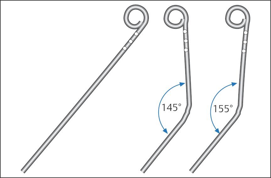
For standard ventriculography we use a pigtail catheter, size 4F or 5F, and access from the femoral artery or from the radial artery. For some specific examinations higher flow rates are required (e.g., mitral regurgitation, high cardiac output), and then a catheter size 7F is occasionally used. The Sones catheter, which many operators still regularly use with radial access, also allows high flow rates of ≥ 22 mL/s starting at 5F. However, with the Sones catheter relatively low injection rates have to be used, as flow rates that are too high can lead to abrupt catheter movements due to recoil and thus can cause ventricular tachyarrhythmias or, in a worst-case scenario, a direct contrast medium injection into the myocardium.
 Technique
For introducing the catheter into the left ventricle, the same general rules for handling the catheters apply as with coronary angiography. The catheter is advanced to the ascending aorta to the level of the sinuses of Valsalva. Different projection planes are suitable for retrograde left heart catheterization; many operators use the AP view, others a RAO or LAO projection.
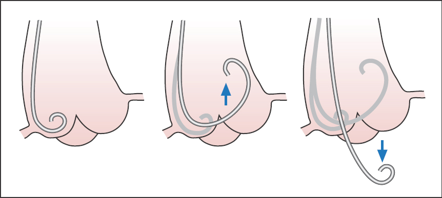
We leave the guidewire in the catheter shaft to provide sufficient stability while advancing the catheter. The catheter is pushed onto the aortic valve with light pressure, slightly pulled back during a slight rotation, and introduced into the left ventricle. There it is placed extrasystole-free ideally in the middle of the cavity (Fig. 9.2). Then, the left ventricular pressure curve is recorded and left ventricular end-diastolic pressure is determined.
Catheterization is relatively easy in most cases; occasionally, however, several attempts are required. The specific difficulties in crossing severely sclerotic or calcified aortic valves in older patients or in patients with aortic stenosis will be discussed separately in the chapter on aortic stenosis (Chapter 14).
The Left Ventricular Angiogram
 Injection Technique/Catheter Position
The optimal position is reached when the catheter tip lies freely in the middle of the left ventricular cavity without triggering extrasystoles. This is true for all catheters. The free and correct catheter position can be verified by forceful manual test injection of ~5 mL of contrast medium. If the catheter tip is located too close to the base, the contrast medium is predominantly injected into the left ventricular outflow tract and the apex is therefore not sufficiently opacified. Furthermore, in this position the catheter can cause artificial mitral regurgitation by disturbing mitral valve function. Extrasystoles are caused by contact with the septum of the apex at the inferior wall. If the catheter is in the middle, a slight correction is generally sufficient to achieve an undisturbed rhythm. In particular, an apically positioned catheter tip can lead to numerous extrasystoles when contrast medium is injected during left ventriculography. This can significantly impair proper assessment of contractile function.
 Injection Technique with Contrast Power Injector
After correct placement, the catheter is connected to a high-power injector with transparent plastic tubing. To prevent air from getting into the system, the syringe plunger advances slowly during the process of connecting. This leads to contrast medium slowly dripping from the plastic tubing, while at the same time blood flows back from the catheter.
 One must pay strict attention to ensuring that the system is free of air bubbles. After connecting the catheter, a little blood can be aspirated from the catheter into the injection tubing with the injection pump to make sure that no air bubbles are present.
The goal of left ventriculography is a complete opacification of the left ventricle without arrhythmia and without artificial mitral regurgitation. For this purpose 15 to 40 mL of contrast medium is injected within 2 to 3 seconds. This corresponds to an injection rate of 8 to 16 mL/s. When using a 4F or 5F pigtail catheter for routine catheterization, between 15 and 30 mL of contrast medium is injected at an injection rate of 10 to 12 mL/s.
During the injection phase, contrast medium filling of the ventricle is monitored on the screen.
The operator should keep the catheter in his or her hand during the entire injection phase to be able to immediately pull back the catheter in case of complications, such as endomyocardial contrast medium injection. If extrasystoles occur, pulling the catheter back by 2 to 3 cm usually produces a position associated with greater rhythm stability for the remainder of the injection phase.
Injecting large volumes of contrast medium causes a marked feeling of warmth that spreads diffusely throughout the body secondarily to vasodilatation and persists for ~30 seconds. The patient should be prepared for this before injection so as not to become unnecessarily alarmed by this essentially harmless phenomenon.
To prevent the diaphragm from overlapping with the ventricular silhouette, ventriculography can be done if required in deep inspiration; however, the patient should not do a Valsalva maneuver. To assess left ventricular volumes under physiological conditions, including determination by ventriculography of stroke volume and especially for assessment of the regurgitant fraction in cases of valvular regurgitation, the ventriculogram should be performed at the mean respiratory level. For similar reasons it is important to avoid an inadvertent Valsalva maneuver by the patient during a breath hold.
Ventriculogram with Impaired Ventricular Function
Every contrast medium administration is an acute volume load; therefore, contrast medium volume has to be kept to a minimum in patients with impaired ventricular function and an end-diastolic left ventricular pressure of more than 25 mm Hg. This needs to be balanced against the amount of contrast required for sufficient opacification of the usually also dilated left ventricle.
 If ventricular function cannot be sufficiently evaluated due to suboptimal opacification, then the reduced amount of contrast medium administered was useless.
If required, one can try to reduce the increased end-diastolic pressure before ventriculography with administration of nitrates. Also, with monoplane catheter systems one can in many cases do without an additional ventriculogram in a second plane (LAO), if the expected benefit is not in a reasonable relation to the risk of additional exposure to contrast medium.
 If the end-diastolic pressure is above 35 mm Hg, every additional contrast medium injection can lead to left heart decompensation and pulmonary edema!
Therefore, the fundamental question for the operator is whether the left ventriculogram is required in the patient or whether other imaging modalities, such as echocardiography or MRI, are preferable for assessing left ventricular function.
 Projections
The two standard projections for left ventriculography are 30° RAO and 60° LAO. Other projections are the lateral projection to assess mitral regurgitation and a 45 to 60° LAO projection with cranial angulation (15–20°) to image a ventricular septal defect.
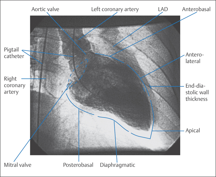
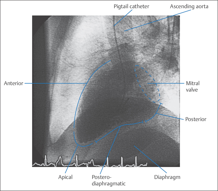
RAO projection (30°). In this view the septum and thus also the anatomical longitudinal axis of the left ventricle are in the projection plane. This allows assessment of the anterolateral wall and the entire apex and the inferior segments of the posterior wall (Fig. 9.3). Basal, medial, and apical wall segments can be differentiated in both the inferior and the anterolateral wall. The mitral valve is viewed tangentially. The left atrium and left ventricle are clearly separated and do not overlap in this projection, so that even mild mitral regurgitation can be easily recognized. The mobility of the posterior mitral valve leaflet can be well assessed, whereas the anterior leaflet overlaps with the aortic valve.
If the ventriculogram is only done in one plane, the RAO projection is the view that can provide the most information. As well as assessing mitral regurgitation and volume determination, this is the projection that primarily permits assessment of left ventricular contraction and analysis of the regional wall motion of many segments of the anterior and posterior wall.
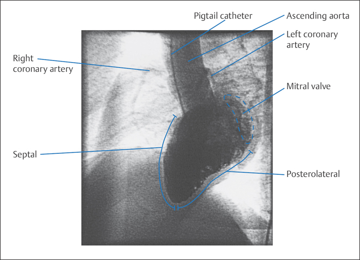
LAO projection (60°). This projection is best suited for assessing the interventricular septum, the left ventricular outflow tract, and the posterolateral wall, which runs from the aorta to the apex and is subdivided into a basal and an apical segment (Fig. 9.4). As the ventricular axis runs in this projection toward the viewer, the apex proper is usually not well delineated but rather overlaps with apical parts of the inferior wall.
At the base of the heart the mitral valve annulus is imaged in a half-oblique position. The mobility of the anterior mitral valve leaflet can be well assessed, also the mobility of the left coronary cusp and right coronary cusp of the aortic valve. This projection is not suitable for evaluating mitral regurgitation. The septum forms the left border and its contractility can be well assessed. This projection is therefore well suited to evaluating the ventricular outflow tract in hypertrophic obstructive cardiomyopathy. A better view of the entire septum can be obtained by additional cranial angulation by 15 to 20°, which will partially offset the foreshortening of the ventricular plane. This is also of significance in extended akinesias or dyskinesias of the anterior wall, which can completely overlap with the septum, so that in the nonangulated view it is visualized as a shadow within the contrast-filled ventricular silhouette.
Lateral projection. In addition to the RAO projection, the lateral projection plane is also suitable for assessing mitral regurgitation. The left atrium is visualized without overlap in front of the descending aorta, and the extent of regurgitation into the left atrium and/or into the pulmonary veins can be well recognized. Viewed from the mitral valve in the direction of the diaphragm, the ventricular silhouette is formed by the posterior and posteroinferior wall, whereas the anterior cardiac silhouette, viewed from the apex to the aorta, is formed by segments of the anterior wall and the septum (Fig. 9.5). Most segments of the anterior wall and lateral free wall are located in the projection plane and therefore cannot be evaluated.
 Complications of Ventriculography
Ventricular tachyarrhythmias. The most common complications of ventriculography are ventricular tachyarrhythmias. These are usually mechanically induced by the catheter and cease after correcting the catheter position or, if necessary, after removing the catheter from the ventricle. Ventricular arrhythmias are more commonly seen with catheters with open tips (e.g., Sones). Sustained ventricular tachyarrhythmias that require electrical cardioversion are rare.
Intramyocardial contrast medium injection. This is a rare complication, and usually without consequence if no perforation is present (monitor with serial echocardiograms)! More common with open-end catheters.
Ventricular perforation. While ventricular perforation is rare, it has potentially life-threatening consequences. This complication occurs predominantly during technically difficult left heart catheterizations with straight guidewires, for example, with aortic stenosis (Fig. 9.6). Even if perforation is only suspected, the catheter has to be pulled back immediately. Further treatment depends upon the clinical course.
With pericardial effusion and imminent tamponade, pericardiocentesis is performed, and, if required, surgical repair of the defect. In cases where the effusion is hemodynamically insignificant and the patient has stable circulatory function, serial echocardiograms may be used to monitor resorption of the effusion. To detect this complication early or to prevent it, an initial manual test injection of contrast medium is indicated after every difficult catheterization of the left ventricle. The catheter can be connected to the high-power injector only after a normal test injection.
 To detect a perforation it is not sufficient to monitor the LV pressure curve, because more proximal side holes of the pigtail catheter can still be inside the cavity.
Embolization of air or thrombi. This is also a very rare complication, which should not occur with careful preparation with complete removal of bubbles from the power injector and the tubing as well as thorough flushing of the catheter.
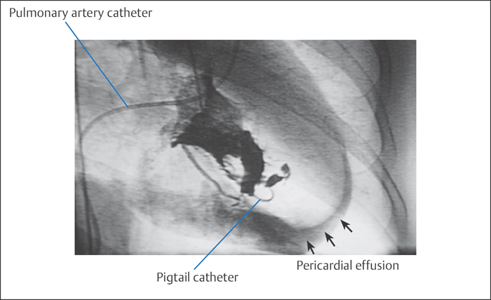
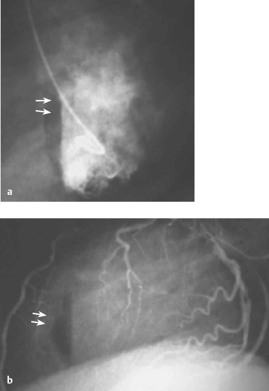
Fig. 9.7 a, b Air injection into the left ventricle.
a Visible as anterior air crescent in the left ventriculogram (60° LAO projection).
b With lateral fluoroscopy during left coronary angiography.
Embolization of air or thrombi can lead to severe cardiac and neurological complications. A rare example of an air embolization is shown in Fig. 9.7: after accidental air injection into the left ventricle, which can be seen crescent-shaped below the septum; air embolization into the right coronary artery occurred with subsequent occlusion of the vessel and acute posterior wall ischemia. With complete immobilization of the patient and with intracoronary administration of nitroglycerin, the air was completely resorbed both from the right coronary artery and from the left ventricle within ~55 minutes. There were no persistent adverse sequelae.
 It is important in this situation to immobilize the patient until the air has been completely resorbed to prevent systemic embolization.
 Interpretation of the Left Ventriculogram
Regional Wall Motion Abnormalities
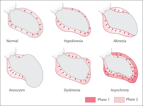
In most catheterization laboratories regional wall motion abnormalities of the left ventricle are assessed qualitatively using the terminology introduced by Herman et al (Fig. 9.8):
 Normokinesis: normal wall motion
 Hypokinesis: impaired but not absent wall motion.
 Akinesis: immobility of the respective area during systole and diastole
 Dyskinesis: systolic outward movement of the myocardium
 Aneurysm: clear distinction of the dyskinetic segment from the other segments during both systole and diastole
 Asynchrony: individual wall segments do not contract in a synchronized fashion but with temporal delay; systolic contraction may be unimpaired in the individual segments
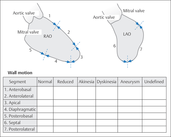
For standardized documentation of left ventricular wall motion abnormalities, the reporting system proposed by the American Heart Association can be used (Fig. 9.9).
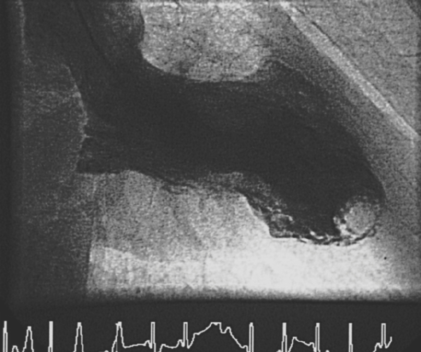
Particularly in the case of marked akinesis and dyskinesis, the operator must remain vigilant for possible intraventricular thrombi both during placement of the pigtail catheter and during coding of the left ventriculogram (Fig. 9.10).
In general clinical practice the quantitative assessment of regional wall motion abnormalities has a more subordinate role. More significant are global ejection fraction, LVEDP, qualitative evaluation of the regional wall motion abnormalities and functional integrity of the myocardium (e.g., hibernation, stunning). None of the methods described below has gained general acceptance as standard practice.
Nevertheless, especially in the case of coronary interventions regional wall motion analyses allow a more precise quantification of changes in the area supplied by an interventionally treated coronary artery, for example, after treatment of a severe stenosis or after recanalization of a coronary artery after acute myocardial infarction.
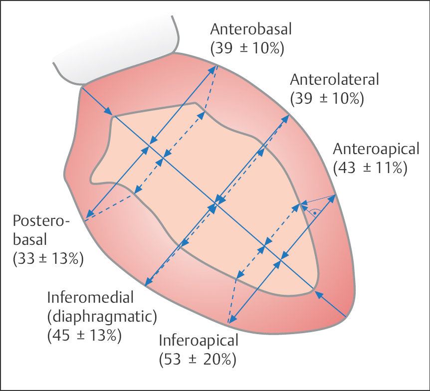
One of the simplest methods is the orthogonal system with subdivision of the left ventriculogram (RAO projection) into three equidistant lateral axes. The percentage axis or fiber shortening of the individual axes is calculated as follows:

Normal values for the shortening fraction (SF) are shown in Fig. 9.11. However, the variability of normal wall motion is substantial, so the method is rarely used now.
For the computer-assisted radial system of wall motion analysis, the regional shortening fraction is assessed in relation to the center of the ventricular area or to the center of the longitudinal ventricular axis. For the center-of-gravity method according to Wong et al, the radial shortening fraction is determined in five wall segments (Fig. 9.12a).
The center-line method evaluates the regional wall motion in relation to the results in a normal control group. A center line between the end-diastolic and end-systolic contours of the left ventricle is determined, and the wall motion is calculated at 100 equidistant lines perpendicular to this center line. (Fig. 9.12b).
With the Slager method the regional contribution of individual wall segments to global ejection fraction is calculated from the movement between end-systole and end-diastole of specified points of the left ventricular endocardium. Here, too, the findings are compared with the wall motion parameters of a normal control group (Fig. 9.12c).
Ventricular Volume/Ventricular Mass
Basic theory. Left ventricular volumes are measured by quantitative analysis of the recorded ventriculogram. The most precise method to calculate the volume is based on the geometric approximation of the ventricle as an ellipsoid. The volume of an ellipsoid is calculated with the following equation (Fig. 9.13):
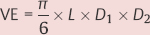
where
VE = ellipsoid volume
L = longitudinal diameter
D1 = first transverse diameter
D2 = second transverse diameter (orthogonal to D1)
Axis method. In the ventriculogram the longitudinal diameter (defined as the longest axis within the cardiac silhouette) is calculated as follows. In the RAO projection the distance from the apex to the center of the aortic valve or to the aortomitral transition point is determined. The transverse diameter is measured in the middle of the longitudinal axis (with biplane measurement both in RAO and LAO; with monoplane measurement D1 is equated with D2).
Stay updated, free articles. Join our Telegram channel

Full access? Get Clinical Tree


