CHAPTER 85 Catheter Ablation of Arrhythmias
INDICATIONS FOR AN ELECTROPHYSIOLOGY STUDY
The indications for an EP study have been delineated by the American College of Cardiology and the American Heart Association (ACC/AHA).1,2 Class I recommendations involve conditions for which there is a general agreement among experts and evidence that an EP study would provide useful and important information for patient treatment. Class II recommendations involve conditions for which EP studies are frequently performed, but there is less certainty about the usefulness of the information obtained. There is a dichotomy among experts as to the benefit of EP studies in these patients. Class III recommendations involve conditions for which there is general consensus that an EP study is not useful.
CATHETER ABLATION
Catheter-based ablation techniques have been so successful in treating a variety of arrhythmias that they have virtually replaced surgical approaches. In a catheter-based ablation, energy is delivered to a precise area of the heart. This is typically on the endocardial surface of the heart, although closed-chest catheter ablation to the epicardial surface of the heart via the subxiphoid approach is now performed in many centers.6,7
Pace mapping is a mapping technique that can be used when the patient is not in the arrhythmia.8 It is often used in conjunction with activation mapping as a second confirmatory test to determine the accuracy of the selected site for ablation, but it can also be used as a stand-alone mapping technique if the documented clinical arrhythmia cannot be induced during an EP study or is not hemodynamically tolerated. Pace mapping entails pacing the suspected target area for ablation at a rate similar to that of the clinical arrhythmia and comparing the 12-lead electrocardiogram with the ECG of the arrhythmia. A good pace map has an exact QRS match in 12 out of 12 leads. When minor differences in ECG configuration and amplitude are sought, the spatial resolution of pace mapping can be as good as 5 mm.9 Pace mapping also compares the intracardiac activation sequence seen on the EP catheters with the sequence observed during the arrhythmia.
There are also specialized three-dimensional (3D) nonfluoroscopic systems to assist with intracardiac mapping. Most commonly used are the CARTO system (Biosense Webster) and the ESI system (St. Jude Medical). The CARTO electroanatomic mapping system allows 3D electroanatomic mapping with a low-intensity magnetic field that allows localization of the mapping catheter with six degrees of freedom. The accuracy of this system has been described as 0.7 mm and five degrees.10 ESI is a noncontact mapping system that generates mathematically derived electrograms and places them on a map of a cardiac chamber defined by a second, roving contact catheter.11 It uses a 64-electrode noncontact balloon catheter and computes 3360 virtual endocardial electrograms simultaneously.12 These systems or other localizing systems can greatly reduce the amount of fluoroscopy time and may contribute to eliminating the need for biplane fluoroscopy systems.
RF current is typically delivered in a unipolar configuration from the distal tip of the ablation catheter to a cutaneous grounding patch. The energy is generated as an alternating current with a frequency of 300 to 750 kHz.13 These frequencies produce effective heating with negligible muscle stimulation. During RF ablation, the electrical energy is converted to thermal energy by resistive heating. Most of the heating is concentrated at the tip of the catheter because of the small surface area of the tip relative to the cutaneous patch. The heat that is generated is transferred to the adjacent cardiac tissue primarily by conduction and to a lesser extent by radiation, which decreases by the fourth power of the distance from the catheter tip. At steady state, the RF lesion size is proportional to the temperature measured at the tissue–catheter interface, as well as being proportional to the RF power amplitude.14
RF ablation results in thermal injury with coagulation necrosis when tissue heating exceeds approximately 50° C for at least 10 seconds.13–16 As heat is produced at the catheter–myocardium interface, the impedance drops. A drop of 5 to 10 Ω is a sign of conductive heating to the adjacent tissue. The time to electrophysiologic effect after onset of RF current delivery is often shorter than might be anticipated for a pure thermal mechanism based on the documented rate of tissue temperature rise contiguous to the electrode. This raises the possibility that there is a contribution of a direct electrical effect in addition to the thermal effect of RF.
RF lesion size and power delivery are limited by tissue heating at the catheter–tissue interface on the endocardium. Newer ablation systems use external or internal saline irrigation to cool the catheter tip, which allows greater power delivery and the creation of deeper and larger lesions.17 The formation of coagulum may also be decreased with these systems. The catheters typically infuse saline either in a closed system running to the catheter tip or in an open system in which saline flows out small holes at the catheter tip at 17 to 30 mL/min during ablation, similar to irrigated surgical RF ablation devices. Externally irrigated ablation catheters have been increasingly used for ablation procedures for the treatment of ventricular tachycardia and atrial fibrillation.18,19
Cryoablation has been used in the surgical treatment of arrhythmias since the 1980s. Near-transmural lesions can be produced intraoperatively at temperatures of −60° C in the presence of cold cardioplegia. The blood pool presents catheter-based cryoablation systems with a major impediment in achieving adequate temperature. However, a catheter-based closed coolant system has been developed and is in clinical use. The major advantage is the ability to induce a nonpermanent change in tissue conduction—“ice mapping”—followed by a permanent lesion if the ice mapping reveals a desirable location. This method has been used surgically, with temperatures of approximately 0° C producing transient loss of electrical function and −60° C producing irreversible damage.20 A closed-chest approach has to deal with the warming effect of the circulating blood pool, and mean temperatures of −27° C were needed to achieve transient altering of electrical function.21 However, the temperature required for irreversible damage was similar to that needed in surgery (−58° C). Cryoablation catheters are most commonly used in the pediatric population and in ablations performed near the intrinsic conduction system, where the risk of developing complete heart block is elevated.
SPECIFIC ARRHYTHMIAS
AV Nodal Reentrant Tachycardia
Atrioventricular nodal tachycardia (AVNRT) is the most common form of supraventricular tachycardia.22,23 Medically, this arrhythmia is often treated with AV nodal blocking agents, as well as occasionally with antiarrhythmic agents. The ability to cure this arrhythmia with a safe, well-tolerated, and highly efficacious catheter ablation has made this a viable option for first-line therapy of AVNRT.24
The AV node lies within the triangle of Koch, an area confined by the septal leaflet of the tricuspid valve inferiorly, the tendon of Todaro superiorly, and the coronary sinus os posteriorly.25 In 1956, Moe and colleagues described physiologic evidence for a dual AV nodal pathway system.26 These pathways were termed “slow” and “fast” based on their conduction time. However, there are no specific anatomic pathways that have been described that correlate with the fast and slow pathways. The functional dissociation of AV conduction into fast and slow pathways provides the substrate most often associated with AVNRT. The fast pathway normally lies at the apex of the triangle of Koch, and the slow pathway at the base, near the coronary sinus os. However, there is often heterogeneity of atrial activation, and these locations are not universal.
Typical or “common” AVNRT is usually initiated when a premature atrial impulse blocks in the fast pathway, conducts over the slow pathway, then reenters the fast pathway in the retrograde direction (Fig. 85-1). This “slow-fast” AVNRT is responsible for approximately 90% of cases. The atypical or “uncommon” form of AVNRT uses the slow pathway retrogradely and the fast pathway anterogradely. Uncommonly, two relatively slow pathways constitute the reentry circuit (“slow-slow”).
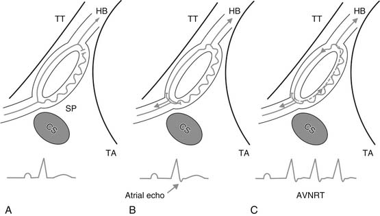
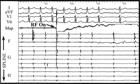
Initial catheter ablation of AVNRT targeted the fast pathway in the anterior interatrial septum.27 Ablation at the apex of the triangle of Koch in the region of the fast pathway was more than 90% successful, but it carried an unacceptably high risk of AV block (5% to 10%). Ablation of the slow pathway was proposed as an alternative to ablation of the fast pathway.28 It is accomplished via a posterior approach, with the ablation catheter initially positioned near the coronary sinus os, at the base of the triangle of Koch (see Fig. 85-1). RF current in the slow pathway region is often accompanied by transient accelerated junctional rhythm with rapid retrograde atrial conduction. This rhythm serves as a marker of a potentially successful ablation. A rapid junctional tachycardia can be a marker for complete heart block, and ablation should be halted if it is seen.29 Energy delivery should also be stopped if AV block or junctional rhythm with retrograde block is seen. Ablation is performed under continuous fluoroscopic monitoring to ensure catheter stability. In approximately 40% of cases, dual pathways are still present after ablation, but sustained ANVRT cannot be induced. Single AV nodal complexes (“echo beats”) are observed in three fourths of these patients with dual pathways after ablation, with block always occurring antegradely in the slow pathway. The success rate using a slow pathway approach is in excess of 95%.30 Slow pathway ablation is preferred to ablation of the fast pathway because although the success rates are equivalent, slow pathway ablation has a much lower risk of complete heart block (1% to 2%).
Atrial Tachycardia
Atrial tachycardias are usually focal arrhythmias originating in the left or right atria with rates of 100 to 220 beats per minute (bpm). The mechanism of atrial tachycardias may be automatic or triggered from focal sites, or they may be micro-reentrant, involving a small area of atrial myocardium. Atrial tachycardias that are incessant and caused by abnormal automaticity or triggered activity are most amenable to ablation. These arrhythmias tend to be resistant to drug therapy.31 Micro-reentrant atrial tachycardias are frequently easily managed pharmacologically, making ablation a second-line therapy. Atrial tachycardias from the left atrium are commonly seen after atrial fibrillation ablation procedures.
Incessant focal atrial tachycardias can occur from a variety of locations in the heart but seem to have a propensity for the crista terminalis, both atrial appendages, the coronary sinus, the regions of the mitral and tricuspid anuli, and the pulmonary veins. It is unclear why these structures are prone to develop these rhythms. It has been postulated that regions such as the crista terminalis are sources of automatic atrial tachycardias because of relatively poor cell-to-cell coupling.32 Fractionated electrograms at successful ablation sites may be markers of the nonuniform anisotropic substrate because poor coupling allows focal automaticity to occur. In adults, atrial tachycardia foci are somewhat more common in the right atrium, and multiple foci are present in 10% to 15% of patients.
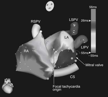
Because the majority of incessant atrial tachycardias are focal in origin, the goal of catheter mapping is to find the earliest site of activation (Fig. 85-2). If the tachycardia is not incessant, catecholamine infusion, such as isoproterenol (1 to 4 μg/min intravenously), or atropine (0.5 to 1.0 mg intravenously) may be necessary to induce sustained arrhythmia. The initial localization of the arrhythmia focus is made by analysis of the P-wave morphology and axis. Catheter mapping is performed by identifying the site of earliest atrial activation relative to the onset of the P wave. Three-dimensional nonfluoroscopic intracardiac mapping systems (e.g., CARTO or ESI, described previously) are often used to aid in mapping the atrial activation sequence during tachycardia (Fig. 85-3). Once the catheter is positioned at what appears to be the earliest site of atrial activation, further evidence that it is the correct site of origin can be obtained by pace mapping, which involves pacing at the early intracardiac site and comparing both the resultant paced P-wave morphology with the tachycardia P-wave morphology, as well as comparing the sequence of intracardiac atrial activation during pacing and during the tachycardia.33 Pacing with higher output at the proposed site of ablation also helps confirm that there will be a minimal risk of injury to the surrounding extracardiac structures. This is particularly important in the right atrium, because of the proximity of the phrenic nerve, but left phrenic nerve damage has also been reported.34 Pacing that results in diaphragmatic stimulation precludes ablation at that site.
The success rate of atrial tachycardia ablation is variable. For incessant tachyarrhythmias, the success rate approaches 90%, although the recurrence rate may be as high as 25%.33,35–37 Because the arrhythmia may not be reliably present or inducible at the EP study (factors such as conscious sedation may serve to make them less inducible), a true success rate on an intention-to-treat basis is less than 90%.
Sinoatrial node reentrant tachycardia represents a distinct entity in the category of atrial tachycardias. Criteria for the diagnosis are consistent atrial activation sequence and P-wave morphology in sinus rhythm and tachycardia, consistent initiation and termination with programmed electrical stimulation, and termination of tachycardia with vagal maneuvers or with adenosine.38–40 Catheter ablation can be accomplished with good results and a paucity of complications, typically by ablating in the high posterolateral region of the right atrium at the tail of the sinus node.41
Atrial Flutter
Atrial flutter is a rapid atrial arrhythmia with a rate typically faster than 220 bpm. Typical right atrial isthmus–dependent atrial flutter is a macro-reentrant circuit involving the right atrium. The posterior barrier of the circuit is formed by the crista terminalis and its continuation as the eustachian ridge.42 The anterior barrier in typical flutter is the tricuspid anulus.43 Typical atrial flutter is either clockwise or counterclockwise, depending on the direction of rotation in the frontal plane around the tricuspid anulus. Although counterclockwise flutter is the more common clinical entity, clockwise flutter can be initiated in most patients with typical atrial flutter.44
Catheter ablation of atrial flutter depends on the ability to interrupt the macro-reentrant circuit at a critical narrow portion between barriers to conduction, termed the isthmus. In both counterclockwise and clockwise flutter, the isthmus targeted for ablation lies anterior to the inferior vena cava (IVC) and the eustachian ridge and posterior to the tricuspid anulus. During flutter, this isthmus is a zone of slow conduction.45 Pacing from within this area slightly faster than the tachycardia helps demonstrate whether the flutter uses this critical isthmus (i.e., whether it is isthmus dependent). If pacing in the isthmus at a rate slightly faster than the tachycardia entrains the tachycardia without alteration of the surface ECG flutter wave morphology and the local post-pacing interval equals the tachycardia cycle length, the tachycardia can be termed isthmus dependent. This pacing maneuver proves that the isthmus is a part of the atrial flutter circuit and that ablation in this area will effectively terminate the tachycardia. Non–isthmus-dependent flutters include those with macro-reentry around the coronary sinus os, fossa ovalis, and postoperative incisional scar tissue, and they also include left atrial flutters such as those caused by reentry around pulmonary vein ostia, mitral valve, or ablation scar from prior surgical or catheter ablations.
Ablation of isthmus-dependent atrial flutter consists of creating a line of block across the right atrial cavotricuspid isthmus. Although this has been described for connecting the coronary sinus os to the tricuspid anulus, this approach can be prone to failure because of slow conduction through the eustachian ridge, which is not necessarily a fixed obstacle that produces block.46 This can lead to a lower loop of reentry around the IVC, which meets the flutter loop going around the tricuspid anulus in a figure-of-eight manner.47 Ablation between the tricuspid anulus and the IVC will eliminate lower-loop reentry as well as isthmus-dependent flutter, and it is the preferred ablation method.
Ablation is usually performed during atrial flutter. If flutter is not present at baseline, it can be induced with one or two atrial extrastimuli or rapid atrial pacing (or both) in 90% of patients with atrial flutter and in 95% of patients with isthmus-dependent flutter.48 Ablation can also be performed during pacing from the coronary sinus if the patient is not in atrial flutter at the time of the procedure. In patients in flutter, the arrhythmia is typically terminated during RF application in the isthmus; however, termination does not necessarily mean that the line of block is complete. Lack of complete isthmus block has been described in over 50% of cases when RF energy terminates flutter.32 To increase the success of the procedure, bidirectional block must be demonstrated,49–51 which is done by pacing the coronary sinus catheter, which is medial to the line of isthmus block. When the line of ablation is complete, there is no clockwise propagation through the isthmus, and activation is around the tricuspid anulus in a counterclockwise direction. This is seen on the tricuspid anulus catheter as craniocaudal activation during CS pacing. To verify the bidirectional nature of the block, pacing is performed from the lateral tricuspid anulus, lateral to the line of isthmus block. If the line of block is complete, there is no counterclockwise propagation through the isthmus, and activation is around the tricuspid anulus in a clockwise direction. In addition to bidirectional block, at the conclusion of the procedure split atrial potentials (>100 msec apart) or absence of atrial potentials (electrograms < 0.05 mV) may be seen along the ablation line. If bidirectional block is demonstrated, the incidence of atrial flutter recurrence is less than 10%.48
Stay updated, free articles. Join our Telegram channel

Full access? Get Clinical Tree


