Cardiac Ventriculography
Mauro Moscucci
Robert C. Hendel
Donald Baim was the author on this chapter in the previous edition, and the majority of his contributed text remains in the current chapter.
Cardiac ventriculography is used to define the anatomy and function of the ventricles and related structures in patients with congenital, valvular, coronary, or myopathic heart disease.1, 2, 3, 4, 5 Specifically, left ventriculography may provide valuable information about global and segmental left ventricular function, mitral valvular regurgitation, and the presence, location, and severity of a number of other abnormalities such as ventricular septal defect and hypertrophic cardiomyopathy. As a result, left ventriculography is often included as part of the routine diagnostic cardiac catheterization protocol in a patient being evaluated for coronary artery disease, aortic or mitral valvular disease, unexplained left ventricular failure, or congenital heart disease. Similarly, right ventriculography may provide information about global and segmental right ventricular function and can be especially helpful in patients with congenital heart disease.
INJECTION CATHETERS
To achieve adequate opacification of the left or right ventricle, it is necessary to deliver a relatively large amount of contrast material in a relatively short period of time. In adults, this is best done using a 6F, 7F, or 8F catheter with multiple side holes to allow rapid delivery of contrast material with the catheter remaining in a stable position in the midventricle so as to reduce the risk of arrhythmia. Catheters that have only an end hole (such as the Cournand or multipurpose catheters) are not well suited for left ventriculography, since the contrast jet out of the single end hole can cause the catheter to recoil during contrast delivery, potentially resulting in ventricular ectopic beats, inadequate ventricular opacification, and myocardial staining or even perforation.
Pigtail Catheter
The pigtail catheter (developed by Judkins) has several advantages over an end-hole-only design for left and right ventriculography (Figure 17.1). Its end hole permits its insertion over a J-tipped guidewire so that the pigtail catheter can be advanced safely to the left ventricle from any arterial access site (see Chapter 6), even in the patient with brachiocephalic or iliac arterial tortuosity. The loop shape keeps the end hole away from direct contact with the endocardium, while the multiple side holes on the catheter shaft located up to several centimeters proximal to the pigtail loop provide numerous simultaneous exit paths for the contrast material. These offset jet directions help stabilize the catheter within the left ventricle during contrast injection and reduce the magnitude of catheter recoil. This virtually eliminates the possibility of endocardial staining, since the end hole usually is not positioned adjacent to ventricular trabeculae, and substantially reduces the occurrence of ventricular ectopic beats.
The pigtail usually passes easily across a normal aortic valve, either directly or by prolapsing across the valve leaflets. Passage across a stenotic aortic valve usually requires use of a straight leading guidewire (see Chapter 6). In patients with porcine aortic valve prosthesis, the pigtail generally passes across the bioprosthesis even more easily than do straight catheters such as the multipurpose, since the pigtail configuration seems to prevent the catheter from sliding down into the lateral sinuses outside the support struts. Pigtail catheters can also be passed retrograde across a ball valve prosthesis (Starr-Edwards), but the resulting interference of the catheter shaft with seating of the ball during diastole may cause significant aortic regurgitation. For this purpose, only the smallest-diameter (e.g., 4F) catheter should be used; dwell time across the valve should be kept to a minimum; and the patient should be monitored carefully for hemodynamic deterioration until the catheter is withdrawn from the left ventricle. Of course, no catheter should ever be passed across a tilting-disc aortic valve prosthesis (Bjork-Shiley,
Medtronic-Hall, or St. Jude) because of the risk that the catheter will be entrapped were it to pass through the smaller (minor) orifice of the valve.
Medtronic-Hall, or St. Jude) because of the risk that the catheter will be entrapped were it to pass through the smaller (minor) orifice of the valve.
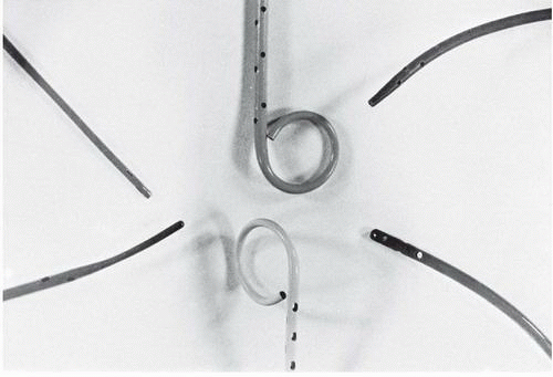 Figure 17.1 Examples of ventriculographic catheters (clockwise from the top): pigtail, 8F (Cook); Gensini, 7F; NIH, 8F; pigtail, 8F (Cordis); Lehman ventriculographic, 8F; Sones, 7.5F tapering to a 5.5F tip (see text for details). |
The original Judkins pigtail design had a straight shaft leading up to the pigtail end. It was thus designed to sit directly under the aortic valve, and just in front of mitral inflow, relying on that inflow to distribute contrast to the apex of the left ventricle. In routine practice, this has been replaced by angled pigtail catheters, which have a 145° to 155° shaft angle at its distal end (just proximal to the side holes). This angle mimics the angle between the aortic root and the long axis of the left ventricle and helps the catheter achieve a central position within the left ventricle. This alignment may be further improved if the heart is pulled into a somewhat more vertical orientation by having the patient take and hold a deep breath during the left ventriculographic injection. Some authors have suggested that catheter manipulation and overall image quality are better with the angled catheter than with the straight pigtail catheter,6 but adequate ventriculography can be achieved with either shape.
Straight Tip Left Ventriculographic Catheters
The Sones catheter was widely used for left ventriculography when catheterization was performed from the brachial approach. The Sones catheter (80-cm Cordis SON-II, Sones Technique, Cordis Corporation, Miami, FL) is particularly suitable for left ventriculography because it has four side holes in addition to its end hole. This catheter comes in 5F, 6F, 7F, and 8F sizes; it tapers to a smaller external diameter near its tip. The catheter will accept a 0.035-inch guidewire, which can be useful in crossing severely stenotic aortic valves. Techniques for traversing a tortuous subclavian artery system and entering the left ventricle with the Sones catheter are discussed in Chapter 8. For left ventriculography, the Sones catheter should be positioned in an axial orientation (parallel to the ventricular long axis), with its tip midway between the aortic valve and left ventricular apex. Low injection rates (see below) usually minimize the extent and forcefulness of catheter recoil. Catheter recoil may still occur, however, with induction of multiple ventricular extrasystoles and potential danger of endocardial staining. Accordingly, the operator should hold the catheter during injection and be prepared to withdraw it if significant recoil develops.
The NIH and Eppendorf catheters have multiple side holes and no end hole (Figure 17.1). They are easily inserted through an arteriotomy (by the brachial approach) or percutaneously through a femoral arterial sheath. The Cordis NIH (polyurethane) and Cook NIH Torcon blue (polyethylene) catheters are relatively soft and unlikely to cause dissection or perforation. The NIH and Eppendorf can be gently prolapsed across the aortic valve, but of course cannot be aided by a leading guidewire because of the lack of an end hole. The Lehman ventriculographic catheter has a tapered closed tip that extends beyond the multiple side holes (Figure 17.1). The tapered tip may assist the operator in manipulating the
catheter through tortuous arteries and across a stenotic aortic valve. Once in the left ventricle, the tip lessens the likelihood of endocardial staining, but may increase the chance of ventricular ectopy during the injection of contrast material.
catheter through tortuous arteries and across a stenotic aortic valve. Once in the left ventricle, the tip lessens the likelihood of endocardial staining, but may increase the chance of ventricular ectopy during the injection of contrast material.
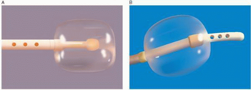 Figure 17.2 The Berman angiographic catheter. A. Normal configuration with side holes proximal to the balloon. B. Reverse configuration with side holes distal to the balloon. The reverse configuration is used for balloon occlusion pulmonary angiography and peripheral angiography. (Courtesy of Arrow International.) |
Balloon Tip Ventriculographic Catheters
The Berman angiographic catheter is a balloon tip catheter that is available in 4F, 5F, 6F, 7F, and 8F sizes (Arrow International). It is used for right ventriculography, pulmonary angiography, peripheral angiography, and in the reverse configuration for balloon occlusion angiography (Figure 17.2). The balloon tip provides the advantage of easier advancement in the right ventricle or in the pulmonary artery, and by keeping the catheter and side holes away from the endocardium, it can reduce the risk of myocardial staining and ventricular arrhythmias.
INJECTION SITE
Adequate opacification of either ventricle is accomplished only if a large amount of contrast material is delivered in a short period of time. Although satisfactory opacification of the left ventricle can sometimes be achieved by injection of contrast material into the left atrium, this requires trans-septal catheterization, does not allow evaluation of mitral valvular incompetence, and may obscure the basal portion of the left ventricle and the aortic valve. Similarly, the left ventricle may be opacified by aortography in patients with significant aortic regurgitation, and the right ventricle may be opacified by injecting contrast material into the venae cavae or right atrium. The best approach to ventriculography in the adult patient, however, is via injection of contrast material directly into the ventricular chamber in question.
In the left ventricle, the optimal catheter position is the midcavity, provided that ventricular ectopy is not a problem (Figure 17.3). The midcavitary position ensures (a) adequate delivery of contrast material to the chamber’s body and apex; (b) lack of interference with mitral valvular function, which would have otherwise produced factitious mitral regurgitation; and (c) positioning of the holes through which the contrast material is injected away from ventricular trabeculae (thereby avoiding a possible cause of endocardial staining). In some patients, however, the midcavitary position induces repetitive ventricular ectopy. In that case, the tip of the catheter is best repositioned in such a way that it lies in the left ventricular inflow tract immediately in front of the posterior leaflet of the mitral valve (Figure 17.4). This position is usually free of ventricular ectopy, but may produce mitral regurgitation if the catheter is too close to the mitral valve. In occasional patients with vigorous ventricular contraction, no stable midventricular position can be found for the catheter. The pigtail catheter can then be advanced to be in continuous contact with the left ventricular apex (assuming that there is no evidence of apical aneurysm of mural thrombus) to allow measurement of left ventricular pressure during stable rhythm and left ventriculography with the rate of contrast injection reduced to 10 mL/second (see below).
When the pigtail catheter is rotated in the left ventricle, it may pass under the chordae. This can be suspected if the catheter shaft passes close to the inferior wall or exhibits an abrupt kink, and can be confirmed if the loop of the pigtail opens up as the catheter is withdrawn back to the left ventricular outflow tract. Because the side holes on the catheter shaft are held in close proximity to the myocardial wall by the chordae, this position increases the risk of myocardial staining and should be corrected before ventriculography is
performed. If repositioning the catheter would be difficult (as in a patient whose stenotic aortic valve has just been crossed) and ventriculography is required, a reduced injection rate should be used as described above for the Sones catheter.
performed. If repositioning the catheter would be difficult (as in a patient whose stenotic aortic valve has just been crossed) and ventriculography is required, a reduced injection rate should be used as described above for the Sones catheter.
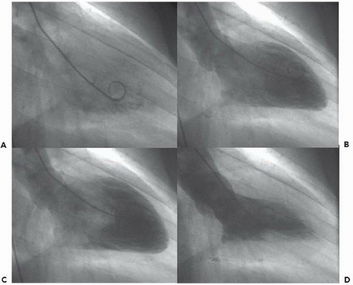 Figure 17.3 An example of midcavitary catheter position for 30° right anterior oblique left ventriculography using an angled pigtail catheter. A. Just before the injection of contrast material. B. At the end of rapid filling. C. At end-diastole (post A wave). D. At end-systole. |
INJECTION RATE AND VOLUME
Rapid delivery of an adequate amount of contrast material requires the use of a power injector. Flow injectors (most commonly, the device manufactured by Medrad) allow one to select both the volume and the rate of delivery of contrast material. Sufficient pressure to deliver the selected volume of injectate in the selected time period is automatically developed, although a maximal pressure limit of roughly 1,000 psi is set to minimize the risk of catheter burst. Of course, this high pressure is not actually delivered to the catheter tip, but is dissipated as frictional losses in the shaft of the catheter. Some injectors permit synchronization of the injection of contrast material with the R wave of the electrocardiogram, so that a set flow rate is delivered in each of several successive diastolic intervals.7 Although this has been said to be a technique that lessens the incidence of ventricular ectopic beats and minimizes the volume of contrast material required for adequate ventricular opacification, our impression is that it offers no clear advantage over the nonsynchronized methods.
Cine left ventriculography is accomplished using an injection rate and volume that depend on (a) the type and size of catheter, (b) the size of the ventricular chamber to be opacified, (c) the approximate ventricular stroke volume, and (d) the pre-ventriculography hemodynamics. Different operators use different catheters and different injection parameters for left ventricular injection. In most cases performed with pigtail catheters, the injection parameters are chosen as 30 to 36 mL injected at the rate of 10 to 12 mL/second (i.e., a 3-second-long injection). Somewhat higher volume and rate may be used in patients with a high cardiac output or large ventricular chamber, and somewhat smaller volumes and rates may be used in smaller or irritable ventricles. When an end-hole (e.g., Sones or multipurpose) catheter is used for left ventriculography, the rate of injection of contrast material should not exceed 7 to 10 mL/second to minimize the chance of recoil and staining. Hand injection through the manifold cannot provide adequate volume and flow rate to fill the ventricle and should be avoided.
Low-osmolar contrast media have substantially improved the safety of left ventriculography in patients with depressed myocardial function, severe coronary artery disease, and/ or aortic stenosis, as discussed in Chapter 2.8, 9, 10, 11 Even so, in patients with hemodynamic evidence of severe left ventricular dysfunction and/or if filling pressures are markedly elevated (>25 mmHg), left ventriculography should be performed only after the elevated filling pressure has been reduced by the administration of intravenous nitroglycerin or sodium nitroprusside. With the current radiographic equipment,12 low-osmolar contrast agents, and techniques using smaller amounts of contrast material, it is a rare case that a patient cannot undergo left ventriculography safely. But failure to take a severely elevated pre-ventriculography pulmonary capillary wedge pressure or left ventricular end-diastolic pressure seriously can lead to disastrous consequences, including intractable pulmonary edema and even death. In any patient with increased risk (LV dysfunction, mural thrombus, renal insufficiency) one should always ask whether noninvasive means of assessing left ventricular function (see below) might not be preferable to contrast ventriculography.
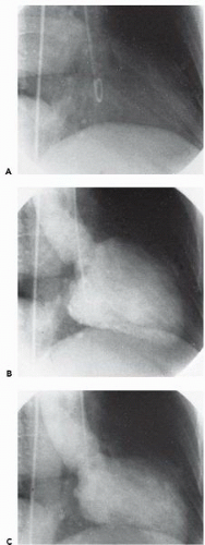 Figure 17.4 An example of a pigtail catheter positioned in the left ventricular inflow tract for 30° right anterior oblique left ventriculography. A. Before the introduction of contrast material. B. At end-diastole. C. At end-systole. Note that this patient has a large anteroapical aneurysm with dyskinesis during systole. |
Before performing a power injection of contrast material, one should take appropriate precautions in filling and firing the power injector to prevent air embolism. The injection syringe is made of siliconized plastic so that the contrast medium and any air may be easily visible. This syringe is usually loaded from a contrast bottle through a short U-shaped straw while the syringe barrel is pointed upward. With the injector still in the vertical position, 30-inch-long sterile roentgenography tubing is connected to the syringe, and all air is expelled from the syringe and tubing by holding the load switch in the forward position as the operator taps the syringe and its Luer-Lok connector to discharge all air bubbles. Alternatively, some laboratories fill the injector by connecting the sterile roentgenography tubing to the coronary manifold, drawing contrast from that supply (generally a slower process, more prone to bubble formation).
Only after all of the bubbles have been expelled in the nose-up position should the injector head be inverted. A fluid-to-fluid connection is accomplished by touching the meniscus of blood spurting from the hub of the catheter to the meniscus of contrast exiting the roentgenography tubing as the technician slowly advances the syringe plunger of the injector manually. When the connection is made, the injector operator stops advancing and begins retracting the plunger until the interface between contrast material and blood can be seen in the roentgenography tubing and verified to be free of air bubbles. Prior to the left ventriculographic run, a test injection of a small amount of contrast material is often performed under fluoroscopic visualization to enable the physician to assess catheter and patient position and confirm that ventricular ectopy does not occur. If the catheter is repositioned, another test injection is recommended before the definitive injection.
Prior to performing the angiogram, the physician should look closely at the injector syringe to confirm that it is filled
with contrast medium, free of air, and oriented in the desired nose-down direction. He/she should grasp the catheter at its hub so that the catheter can be pulled back instantaneously if ventricular extrasystoles, myocardial staining, or other untoward events develop during injection. The technician or other individual firing the injector should be prepared to abort the injection on command from the physician operator in the event of an untoward occurrence. If extrasystoles develop, we withdraw the ventriculographic catheter a distance of approximately 2 to 3 cm after the first extrasystole, which usually results in a quiet position for the remainder of the 3- to 4-second contrast injection.
with contrast medium, free of air, and oriented in the desired nose-down direction. He/she should grasp the catheter at its hub so that the catheter can be pulled back instantaneously if ventricular extrasystoles, myocardial staining, or other untoward events develop during injection. The technician or other individual firing the injector should be prepared to abort the injection on command from the physician operator in the event of an untoward occurrence. If extrasystoles develop, we withdraw the ventriculographic catheter a distance of approximately 2 to 3 cm after the first extrasystole, which usually results in a quiet position for the remainder of the 3- to 4-second contrast injection.
Instructions to the patient regarding respiration during contrast ventriculography vary from laboratory to laboratory. Earlier imaging systems were often inadequate to give good definition of the left ventricular silhouette unless ventriculography was performed during deep inspiration to move the diaphragm out of the radiographic field. With modern imaging systems, excellent definition of the ventricular silhouette can be achieved without the restriction that ventriculography be performed during held deep inspiration. Left ventriculography done during normal quiet breathing allows physiologic interpretation of left ventricular volumes, angiographic stroke volume, and calculated left ventricular regurgitant fraction in cases of valvular regurgitation.
FILMING PROJECTION AND TECHNIQUE
Projections should be used that provide maximal delineation of the structure of interest and minimal overlapping of other structures. The 30° right anterior oblique (RAO) projection eliminates overlap of the left ventricle and the vertebral column; allows one to assess anterior, apical, and inferior segmental wall motion; and places the mitral valve in profile to provide a reliable assessment of the presence and severity of mitral regurgitation. The 60° left anterior oblique (LAO) view allows one to assess ventricular septal integrity and motion, lateral and posterior segmental function, and aortic valvular anatomy. To prevent foreshortening of the left ventricle and visualize the entire length of the interventricular septum in profile, 15° to 30° cranial angulation should be added to the 60° LAO view, and the angiogram should be performed during a sustained deep inspiration to minimize obstruction by the diaphragm. This view allows visualization of ventricular septal defects and the associated left-to-right shunting, or the septal bulge and systolic anterior motion in hypertrophic obstructive cardiomyopathy, or isolated lateral wall motion abnormalities (Figures 17.5 and 17.6). For routine left or right ventriculography, 30 frames per second using the 9-inch field of view allows the best temporal and spatial imaging, but many laboratories now use 15 frames per second for both ventriculography and coronary angiography to reduce radiation exposure (see Chapter 2).
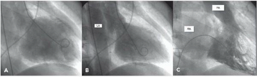 Figure 17.5 Mitral and tricuspid regurgitation. End-diastolic (A) and end-systolic (B) frames from a left ventriculogram performed in the 30° RAO projection in a patient with normal coronaries and presumptive AIDS cardiomyopathy, showing enlarged end-diastolic and end-systolic volumes, reduced ejection fraction of 38%, and 2+ mitral regurgitation. Note the dye movement to the enlarged left atrial volume; the contrast density method underestimates the severity of regurgitation, shown to be moderately severe by a regurgitant fraction of 36% and transesophageal echo. C. End-systolic frame from a right ventriculogram in the same patient performed in the 30° RAO projection showing 2+ tricuspid regurgitation. LA, left atrium; RA, right atrium; PA, pulmonary artery. |
If both RAO and LAO ventriculograms are indicated, it requires two separate injections in a single-plane room. If available, biplane ventriculography is thus preferable to single-plane ventriculography because it allows one to obtain more information at essentially no additional risk to the patient. In the patient with coronary artery disease, biplane left ventriculography provides more information on the location and severity of segmental wall motion abnormalities than does single-plane ventriculography; in the patient with congenital heart disease biplane right ventriculography allows one to assess accurately the anatomy of the right ventricular outflow tract, the pulmonic valve, and the proximal portions of the pulmonary artery. But biplane ventriculography has several disadvantages, including (a) higher cost of the biplane cineangiographic equipment; (b) reduced
quality of cineangiographic imaging in each plane owing to radiation scatter caused by the opposite plane; (c) additional time required to position the biplane equipment appropriately, especially when the brachial approach is used; and (d) additional radiation exposure to personnel in the room. In reality, most laboratories have only one biplane laboratory in their imaging suite, so that almost all left ventriculograms are done single plane. Table 17.1 provides a list of preferred left and right ventriculographic views for various conditions. Additional information on preferred angiographic projections for congenital lesions is provided in Chapter 9 and in Table 9.5.
quality of cineangiographic imaging in each plane owing to radiation scatter caused by the opposite plane; (c) additional time required to position the biplane equipment appropriately, especially when the brachial approach is used; and (d) additional radiation exposure to personnel in the room. In reality, most laboratories have only one biplane laboratory in their imaging suite, so that almost all left ventriculograms are done single plane. Table 17.1 provides a list of preferred left and right ventriculographic views for various conditions. Additional information on preferred angiographic projections for congenital lesions is provided in Chapter 9 and in Table 9.5.
Stay updated, free articles. Join our Telegram channel

Full access? Get Clinical Tree


