Fig. 29.1
Schematic of radiofrequency lesion formation
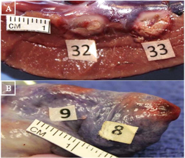
Fig. 29.2
Illustration of depth and width of lesion formation . (A) Left ventricle (8 mm catheter tip; 32: 9.2 mm wide, 10 mm long, 7 mm deep, 16w, 64c, 44 s; 33: 8 mm wide, 11.7 mm long, 7.7 mm deep, 30w, 65c, 42 s). (B) Right atrium (8 mm catheter tip; 8: 6.8 mm wide, 7.2 mm long, 2.2 mm deep 18 W, 63c, 60 s; 9: 5.5 mm wide, 8.2 mm long, 3.7 mm deep 10 W, 65c, 60 s). Pictures from Avitall Lab 2014
The majority of RF ablation catheters are unipolar, that is, where RF energy is delivered at the ablation electrode and then sent to a dispersive pad located on the thigh or back of the patient. A bipolar mechanism consists of energy passing between electrodes of the catheter itself, but the use of this kind of mechanism is not commonly practiced.
29.2.2 The RF Generator
Typically, clinically used RF generators produce frequencies from 100 to 3000 kHz (the range of electrosurgery), with an ablation range of 300–1000 kHz (550 kHz is the FDA-suggested optimal frequency). It is important to note that the high frequency of RF does not depolarize the cardiac tissues, and thus lacks the possibility of triggering deadly arrhythmia (ventricular fibrillation) [1, 11].
In general, an RF generator controls power, temperature, and duration of the applied ablation, while also measuring impedance and temperature during the procedure. Both power and temperature may be set as a maximal control with the latter being typically set as control in clinical procedures, allowing for power delivery to be modulated and thus maintaining a given temperature. Power settings range from 10 to 100 W with temperature ranges dependent on specific models. For instance, the EPT-1000X generator from Boston Scientific (Marlborough, MA, USA) has a temperature range of 30–120 °C (Fig. 29.3). The RF generator allows ablation duration to be set (maximal duration is preset at 120 s; 60 s is commonly used), but ablation can be manually terminated at any time during an application.
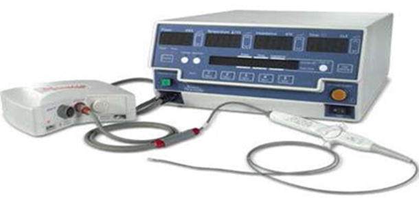
Fig. 29.3
Radiofrequency (RF) generator from Boston Scientific (EPT-1000X). Along with the basic functionality of RF generators, it also provides memory tabs to preset specific values for each variable. This particular system is specifically designed for use with catheters designed from Boston Scientific (Blazer series) and connects to catheter via the Maestro 3000 system. Source: Boston Scientific webpage
29.2.3 Additional RF Clinical Generator Information
It is important for users to understand and verify that maximal power applications via a generator are dependent on a per-catheter basis. For instance, the 4 mm ablation catheter tip electrode’s maximal power is limited to 50 W, while the 8 mm is limited at 65 W [12]. The power limitations were established to minimize the potential of tissue overheating leading to boiling, char, and gas formation within the tissues; in turn, this can cause pressure buildup leading to a burst known as a steam pop and tissue shredding. The RF power supply is also set to a maximal temperature limit which also depends on the catheter being used. For an 8 mm standard tip catheter, a typical maximal temperature of 65 °C is used [12]. It should also be noted that, in general, RF power cannot be applied (or terminates) if the impedance is too high prior to an ablation or rises during an ablation, as this may be an indication of coagulum formation at the tip [5, 6, 13]. The usual catheter-to-tissue impedance is 80–240 Ω [5]. A lower impedance may indicate a system short or failure, whereas a high impedance cutoff is to prevent char formation and ensure that the reference patch electrodes are properly attached to the patient’s skin. If the size, or the contact of the reference electrodes with the skin, is poor, it may lead to severe skin burns (Fig. 29.4a).
Fig. 29.4
(a) Second degree burn from improper patch use. (b) Typical dispersive patch. (c) Sketch of circuit that dispersive pad is used to complete
More specifically, since tissue and blood heating results in denaturation of proteins, blood products can adhere to the catheter thus increasing the impedance (Fig. 29.5a). Importantly, the early detection of impedance rises and automatic terminations of the RF powers can potentially prevent a stroke.
Fig. 29.5
(a) Char formation on a catheter tip. Source: http://drwes.blogspot.com/2007/08/remote-magnetic-catheter-ablation-of.html). (b) Char formation on a lesion on a pulmonary vein with a nonirrigated 8 mm tip. (Picture from Avitall Lab 2014). (c) Depiction of char formation during a catheter ablation. Note the high temperature (70 °C) at tissue–electrode interface. Source: http://wesleytodd.blogspot.com/2013/09/rf-ablation.html
Of interest to note, an atypical generator that is currently awaiting FDA approval—the GENius RF Generator (Medtronic, Inc., Minneapolis, MN, USA)—uses a unique duty-cycle energy delivery system to power a multielectrode catheter called a pulmonary vein ablation catheter (PVAC; Fig. 29.6). The GENius generator is capable of simultaneously delivering power up to 12 electrodes in a temperature-controlled and power-limited manner. The generator is capable of delivering energy in a bipolar, unipolar, or mixed fashion (bipolar:unipolar) 4:1, 2:1, and 1:1 [14, 15].
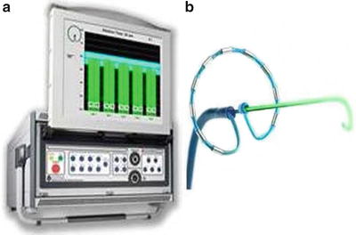
Fig. 29.6
(a) GENius Radiofrequency Generator from Medtronic, Inc. (Minneapolis, MN, USA). The system uses software to control a user-defined temperature, and delivers power to individual electrodes. To maintain the temperature, the power delivery is limited to 10 W at all settings except the 4:1, in which it is limited to 8 W. Power delivery limitation is necessary due to the small surface area of electrodes on the PVAC (3 mm long, 1.5 mm diameter). A display screen shows individual readouts of temperature, power delivery, and time within optimal temperature range for up to 12 individual electrodes [14, 15]. Source: http://www.whichmedicaldevice.com/by-manufacturer/49/151/genius-multi-channel-rf-generator. (b) Pulmonary vein ablation catheter. A multielectrode circumferential ablation catheter anatomically designed for pulmonary vein isolation, powered exclusively by the GENius RF Generator Source. Source: http://www.mprodserver.com/meddevices/pvac
29.2.4 RF Catheter: Standard Features
The baseline design for RF catheters features a simple metal electrode tip (usually platinum) which delivers the radiofrequency energy. A recent study showed that tip metal composition influences lesion formation, with gold-tipped catheters leading to lesions with greater depth which the researchers attributed to the increased conductance of gold compared to platinum [9]. Typically, such catheters are 7–8 F in diameter with the tip size typically ranging between 4 mm and 10 mm in length. Larger tips have greater surface area for circulating blood to cool the ablation electrode. These factors allow for higher power and create larger and deeper lesions [1, 3, 8]. On the other hand, ablation tips that are too large may ultimately create uneven heating which can result in the occurrence of char and/or crater (focal tissue deformations with hyper-contraction zones) formation [3].
In most currently available RF ablation catheters, metal rings are embedded proximally to the ablation tip for the purpose of obtaining focal electrophysiological recordings. Additional electrodes can be placed along the distal portion of the catheter. Importantly, electrophysiological information such as electrogram amplitudes and pacing data can be used to better elucidate type of contact, identify tissues for ablation (or to define tissues that have been ablated or scarred), and give insight related to lesion maturation (Fig. 29.7).
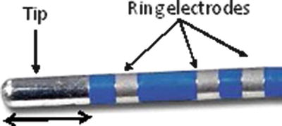
Fig. 29.7
Radiofrequency catheter: 8 mm Dual-8 Therapy Catheter (St. Jude Medical, St. Paul, MN, USA). Picture from Avitall Lab 2014
The handle of most catheters offers bidirectional deflections with specific models providing varying degrees of deflection (Fig. 29.8). Depending on the catheter model, there are various dilators and introducer sheaths available to aid in the insertion of the catheters into the vascular space and the ensuing procedure. The proximal end of the catheter has the electrical umbilical cord that attaches the catheter to the RF generator and to the monitoring/mapping systems simultaneously (Fig. 29.3).
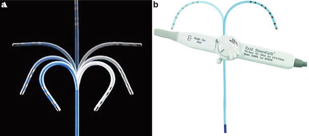
Fig. 29.8
(a) Range of bidirectional deflection seen in a typical radiofrequency catheters. Source: http://www.medicalexpo.com/prod/st-jude-medical/ablation-catheters-bidirectional-irrigated-70886-446600.html. (b) Simple deflection and the handle control for a electrophysiology recording catheter . Source: http://www.eplabdigest.com/articles/Use-a-Steerable-Bi-directional-Coronary-Sinus-Octapolar-Catheter-During-Atrial-Fibrillation
29.2.5 Multielectrode Catheter
One specific type of a multielectrode catheter—the PVAC —was anatomically designed for pulmonary vein isolation (PVI ; Fig. 29.6b). It features ten platinum electrodes that are 3 mm long with a diameter of 1.5 mm, and are spaced apart 3 mm. The diameter of the distal loop is 25 mm; the catheter is a 9 F ablation catheter and can also be used as a mapping catheter. It has bidirectional deflection and distal and proximal retraction that is controlled by two switches located at the handle. The catheter is operated in conjunction with GENius RF Generator. PVAC uses less power (10 W) than most RF catheters with standard metal tips, but due to the small electrode sizes, the current densities are quite comparable [14–16].
29.2.6 Irrigated Tip RF Catheters
The irrigated catheter tip uses a circulating fluid to cool the tip during RF ablation. Open irrigation passes heparinized saline through the tip and discreet irrigation ports, typically 6–12 ports; these fluids then enter into the patient’s blood stream. Porous open irrigation utilizes a similar method to open irrigation, but the fluid “sweats” through a multitude of small pores [8] (Fig. 29.9).
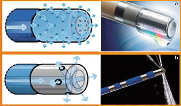
Fig. 29.9
(a) Porous irrigation which “weeps” out. Multiple channel ports evenly disperse fluid. (b) Traditional irrigation with six ports that spray fluid over an area. *Both catheters are from the Thermocool line from Biosense Webster (Diamond Bar, CA, USA). Source: http://www.biosensewebster.com/thermocoolsf.php
The concept of the irrigated tip catheter is that focal cooling at the tip–tissue interface helps to prevent char formation at the interface, i.e., by lowering surface temperature while allowing a large and deep lesion to mature as conductive heating continues unabated into deeper layers. It has been shown that deep tissue exhibits will be subjected to higher temperatures than the tip–tissue interface, with temperatures differences ≥10 °C when ablating with irrigated catheters [6].
With surface tissue temperatures being kept relatively low, greater power and durations can be applied before coagulum formation begins [2]. There is reported evidence that the risk of thrombus, char, and crater formation is reduced when using irrigation [2, 8]. However, irrigation at high power levels (>50 W) has a higher risk of creating a steam pop. As noted above, steam pops can be created by either entrapment of gas at the tip–tissue interface or gas forming just under tissue surface, which then ruptures as the pressure builds within the tissues. This occurs as a result of reaching temperatures that cause boiling [2]. Steam pops can result in shredding of cardiac tissue or perforation, and thus result in severe clinical complications.
In general, irrigated catheters use a specialized irrigation system to control fluid flow rates. While placed within the heart, passive flow rates (≤5 CC/min) are used to keep blood from entering the irrigation pores, thus minimizing clot formation which would stop the irrigation flow. Higher irrigation rates are typically used during the ablation procedure itself. These rates can range from 15 to 30 CC/min, with 30 CC/min being the traditionally recommended value. It is important to note that irrigation flow rates can impact lesion maturation, with high irrigation rates (≥20 CC/min) being shown to reduce lesion diameter but not effecting lesion depth [17]. Additionally the solution used for irrigation can have an effect on lesion formation. Research by Shake et al. has shown that lesion depth is inversely proportional to increasing electrolyte content of irrigation solution; they also showed that the use of nonelectrolyte solutions can result in tissue destruction [18]. Further, some applied irrigation solutions like dextrose are electrically insulating and negatively affect lesion formation [19]. To date, an irrigation solution of 0.9 % sodium chloride saline is recommended for RF irrigation.
29.2.7 Additional Sensors and Modifications of RF Catheters and Technologies: MicroFidelity Technologies
An ablation/mapping product currently available from Boston Scientific, called MicroFidelity (MiFi) Sensor Technology, uniquely utilizes especially sensitive mini electrodes spaced circumferentially around the catheter (Fig. 29.10). The mini electrodes are closely spaced to provide localized readings of tissue while minimizing far field recording. The circumferential placement of these mini electrodes ensures that at least one pair is in direct tissue contact. The MiFi technology is intended to: (1) improve recognition of gaps in linear lesion sequences; (2) help map previously ablated tissues; and (3) provide insights as to the relative maturation of a lesion. Recent research has suggested that electrogram amplitude reductions from mini electrodes can be used to determine the timing of lesion maturation [12]. The nonirrigated MiFi catheter is currently available in 8 mm, while a 4.5 mm irrigated version is currently awaiting FDA approval.
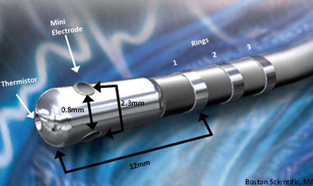
Fig. 29.10
8 mm IntellaTip Mifi XP Temperature: Pictured is a graphical sketch of the locations of various components and spacing between them. Space between mini electrodes is 0.8 mm, space from center of mini electrode to the next is 2.3 mm, and the distance from tip to ring is 12 mm. Source: http://www.bostonscientific.com/redefining-ep/IntellaTip.html
29.2.8 Contact Force
An important aspect of any ablation procedure is understanding the relative amount and type of contact between the electrode and tissue. For example, a poor or partial contact with tissue can result in incomplete lesions and extend procedure times. It was previously reported that good contact ablation has a clear decrease in impedance (10–15 Ω), and results in significantly higher temperatures at the tissue–electrode interface than incomplete or poor contact [5]. The study also showed that better contact with tissue correlated closely with both temperature increases and impedance decreases within the first 5 seconds of an ablation [5]. However, good tissue contact is difficult to assess. Operators have currently employed the use of fluoroscopy, ultrasound, mapping technologies, and electrophysiological readings such as pacing threshold to guide catheters to ablation sites and establish tissue contact. These measures add a level of accuracy, but cannot ascertain the direct degree of contact with target tissue. As a result, contact force sensors have been developed and are being assessed in clinical trials. Today, the two primary contact force sensors being studied are the Thermocool Smart touch (Webster Biosense, Diamond Bar, CA, USA) and the Tacticath Quartz Contact Force catheter (St. Jude Medical, St. Paul, MN, USA) (Fig. 29.11). More specifically, the Tacticath Quartz Contact Force catheter has three built-in optical fibers that will deliver light to tip; a central cavity within the catheter measures micro deformation via a deformable body as contact is made (Fig. 29.11a) [20]. The Thermocool Smart touch utilizes a precision spring and three magnetic sensors built into the tip of a standard RF catheter, to calculate contact force based on micro-deformations of the spring (Fig. 29.11b) [20].
Fig. 29.11
(a) Tacticath quartz contact force catheter (St. Jude Medical, St. Paul, MN, USA). Source: http://professional-intl.sjm.com/products/ep/therapy/advanced-ablation/tactisys-quartz#technology. (b) Thermocool Smart touch Catheter from Webster Biosense (Diamond Bar, CA, USA). Source: http://www.radcliffecardiology.com/articles/thermocool-smarttouch-catheter-evidence-so-far-contact-force-technology-and-role-visitag
Generally, sensed contact forces are measured as grams; in one study, these forces ranged from 2 to 60 g and correlated with decreases in impedance of 9.7–41.7 Ω (respectively) within the first 5 seconds of ablation [21]. In another report, it was shown that when titrating power to achieve an impedance drop of 15 Ω, less power was required with increasing contact force [21]. Also, the utilization of contact force sensors has been described to better predict the occurrence of deeper lesions as well as steam pop and/or thrombus formation [22]. In general, it is considered that information on contact force will allow operators to realize if catheter contact is too great, thus allowing them to ease off and reduce the chance of charring and thrombus. On the other hand, the use of such sensors will allow operators to identify if contact is poor and then move the catheter closer to tissue for proper ablation [21–23].
Related to catheter contact forces for proper lesion formation is catheter tip orientation. Catheter tip orientation has also been shown to impact lesion genesis, with one study showing that smaller catheter tips produce larger lesions in the perpendicular orientation, but larger tips generate larger lesions in parallel orientation [3, 7]. It should be noted that steam pops are more common in the perpendicular orientation [2].
29.3 Cryothermal Ablation
Cryothermal clinical techniques have been used in medicine for several decades, but the cryothermal ablation approach using percutaneous catheters is a more recent development. Cryothermal energy has gained traction as an alternative method for ablating cardiac tissue with RF, but one needs to understand that it relies on a significantly different mode of lesion formation, that is, extracting heat from tissues to induce freezing [24]. Currently, in most procedures where cryoablation has been used, individuals utilize either 9F 8 mm metallic tipped catheters or the 23 and 28 mm diameter cryoballoons; these have been employed to treat atrial fibrillation, atrial flutter, and atrial-ventricular nodal reentrant tachycardia, along with other forms of tachycardia [25–28].
29.3.1 Mechanism of Cryoablation
Cryoablative technologies commonly utilize the circulation of a refrigerant in a closed, pressurized system to rapidly cool the target tissues. These circuits capitalize on the Joules–Thomson effect to deliver full cooling of the refrigerant, such as liquid nitrous oxide (−88.6 °C), to the distal catheter tips. The Joules–Thomson effect is the phenomena where liquid enters an expansion chamber, where it then rapidly cools upon expansion and transitions from a liquid to a gas.
As cardiac tissue cools, it becomes less excitable, electrical conductance slows, and cellular metabolic processes shut down (i.e., when tissue temperature reaches <20 °C). It is important to note that from 0 to −5 °C, the loss of function in most excitable tissues can be restored by allowing the tissue to thaw, but from −5 to −15 °C there is a delay between thaw and restoration of function. This return to function after freezing is known as reversible suppression . Cardiac tissues held at −20 °C for ≥4 min sustain permanent damage and electrical silence [29]. Furthermore, prolonged freezing between temperatures of −10 and −25 °C will typically result in permanent damage, but extreme cold temperatures of ≤−50 °C will result in permanent damage regardless of the therapeutic durations [29, 30]. Cryothermal injury is characterized by three distinct stages: (1) a freeze/thaw cycle; (2) a hemorrhage and inflammation phase; and (3) a fibrosis replacement phase [31, 32]. More specifically, ice crystal formation that occurs within cells causes irreversible damage to subcellular organelles, the most important of which are mitochondria; the electron transport chain of mitochondria is particularly susceptible to ice formation. Once mitochondria are compromised, the cell loses its ability to generate energy and, along with damage to other key organelles, dies. Additionally, coagulative necrosis results shortly after ablation and dead tissue is gradually replaced with fibrosis. The ablation of myocardium by cryothermal energy is considered to help maintain the ultrastructure (due to resistivity of fibroblasts and collagen to freezing), and therapeutic borders are sharply demarcated [30, 33]. Furthermore, it has been reported that a significant decrease in thrombus formation has been associated with the clinical use of cryoablation (Fig. 29.12) [25, 28, 29, 34].
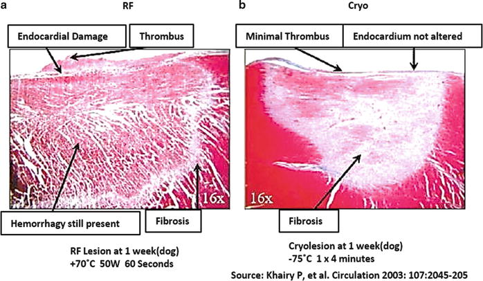
Fig. 29.12
(a) Radiofrequency lesion; note hemorrhaged tissue and nonhomogenous fibrosis. (b) Lesion derived from cryothermal treatment, showing well-demarcated lesion with homogenous fibrosis and no remaining hemorrhage [29]
From a therapeutic delivery standpoint, as refrigerant cools the tissue, ice forms at the tissue contact site. Unlike radiofrequency, the cryo-catheter or cryoballoon outer surfaces will adhere to the applied tissues stabilizing them in place, an important factor for tissue contact during ablation. It should be noted that, depending on the extent of the tissue contact and blood flow, cryotherapy may require 2–5 min to reach temperatures low enough to induce permanent tissue damage [33].
As described above, a unique phenomenon of cryotherapy is the ability to reversibly silence tissues through gentle freezing (0 to −15 °C). By electrically silencing certain tissues an operator performs what is called cryomapping, which aids one to determine which tissues are problematic and require ablation without causing widespread damage [31, 34]. This technique has been shown to be particularly effective with treatment aimed at AV nodal reentrant tachycardias [37].
29.3.2 Available Tools for the Application of Cryotherapies
The delivery of cryotherapy via catheters requires a cryoconsole for operation. Typically, the cryoconsole is connected to catheters via an electrical umbilical cord and liquid gas line. The console performs several critical functions, specifically it: (1) houses the refrigerant (nitrous oxide); (2) creates a vacuum for return of the gas from the catheter; (3) monitors internal temperatures and pressures; and (4) controls the flow of refrigerant to the catheter. If the circuit for the refrigerant is in anyway compromised, the console automatically shuts down the system, deflates the balloon (in the case of balloon catheters), and alerts operators to the issues detected. Currently, such consoles utilize a touchscreen to give readouts of pressure and internal temperature, and also control the functions of the catheter (Fig. 29.13). Refrigerant (nitrous oxide gas) is recycled through the console and then passed to the hospital’s disposal system.
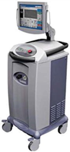
Fig. 29.13
Cryocath console from Medtronic, Inc. (Minneapolis, MN, USA). Source: http://www.medicalexpo.com/prod/medtronic/mobile-cryosurgery-units-70691-441874.html
Currently, clinically available cryo-catheters come in two distinct types—traditional tip ablation catheters and balloon. For example, the Freezor Max from Medtronic, Inc. (Fig. 29.14) has an 8 mm tip with electrodes at the tip and on three subsequent rings, allowing for electrophysiological recordings/mapping. This particular catheter utilizes unidirectional deflections; it fits into a 10 F introducer and comes equipped with a thermocouple that allows for monitoring temperature at the catheter tip. There are two models currently available, one 55 mm and the other 66 mm (handle to tip length). These cryo-catheters feature a central lumen for the passage of refrigerant, which then terminates at the tip of the catheter. A larger lumen is kept under vacuum which returns the refrigerant to the delivery system for disposal. Also, pending model variability, there are typically deflection wires, thermocouple wires, and electrical leads extending to the handle. Handles will feature an electrical umbilical cord, deflection controls, and a gas connector (these are terminated onto the cryoconsole). The tip-based catheters are commonly used to treat pediatric arrhythmia. Additionally, these catheters are also used to treat paroxysmal atrial fibrillation by ablating focal triggers, and are used in conjunction with cryoballoon catheters as spot treatment to complete left atrial PVI procedures.
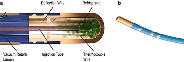
Fig. 29.14
(a) General schematic of the inner components of a tip-based cryo-catheter. (b) Freezor Max 3 from Medtronic, Inc. (Minneapolis, MN, USA). Source: http://www.medtronic.com/
The cryoballoon catheters were anatomically designed for use in PVI. They utilize the same functional mechanism as the tip-based cryo-catheters (i.e., with a central lumen supplying refrigerant and a larger lumen acting as a vacuum return). Uniquely, the cryoballoon catheters feature an inflatable balloon that is designed to generate a circumferential lesion around the balloon and thus treat pulmonary veins. There are currently two sizes of balloons available clinically, 23 and 28 mm. These balloons are made of a compliant material that can withstand the high pressures. Additionally, an outer balloon is employed as a safety feature, in the event of an internal balloon rupture or leak. Importantly, the space between the two balloons is under constant vacuum and any change in pressure immediately results in termination of the refrigerant delivery and suction of gas from the balloon. An internal thermocouple monitors balloon internal temperature. Current models do not feature any electrodes for electrophysiological readings, but they do feature a central lumen where an Achieve mapping catheter (3.3F lasso type catheter) can be maneuvered to the distal end to provide the ability to monitor pulmonary vein electrical activities (Fig. 29.15). To date, due to the size and stiffness of the cryoballoon, catheters have deflections that are very limited. Furthermore, the deployment of the balloon catheter in the left atrium at the os of the pulmonary veins require the use of a 12F sheath, which is introduced into the femoral vein and transseptally into the left atrium; currently, this sheath has unidirectional deflection which helps to facilitate the proper positioning of the balloon catheter.
 < div class='tao-gold-member'>


Only gold members can continue reading. Log In or Register to continue
Stay updated, free articles. Join our Telegram channel
Full access? Get Clinical Tree
