Atrial Flutter
Patrick Tchou
Introduction
The term atrial flutter has traditionally referred to an atrial tachycardia with monomorphic P waves, sometimes referred to as flutter waves, without an isoelectric baseline, having rates in the range of 240 to 300 beats per minute. The term atrial tachycardia has frequently been used for atrial rates less than 240 beats per minute because these tend to have an isoelectric baseline between individual P waves. However, with increasing understanding of the mechanisms of atrial reentrant rhythms, the modern use of the term atrial flutter refers to a regular reentrant tachycardia within the atria having a definable reentrant circuit by our current mapping techniques, also called a macro reentrant atrial tachycardia. The term atrial tachycardia or focal atrial tachycardia tends to be used to describe a tachycardia with an automatic mechanism arising from a narrow focus or, perhaps, a reentrant mechanism confined to a narrow region too limited for current mapping systems to resolve (1). Although atrial flutter as a phenomenon was described around a century ago (2), the mechanisms of this arrhythmia in the human heart have only relatively recently been elucidated with the development of activation mapping systems capable of displaying the reentrant activation wavefront.
Mechanism of Atrial Flutter: The Reentrant Circuit
For a reentrant tachycardia to exist, it must have a reentrant pathway within the myocardium that is formed by conducting tissue around a barrier. Two types of barriers are thought to be involved in demarcating the reentrant circuit of atrial flutter, anatomic barriers and functional barriers. Anatomic barriers can be structures such as the atrioventricular valves, the venous openings into the atria, or scars from surgical incisions or other degenerative/inflammatory conditions affecting the myocardium. The anatomy of the coronary sinus can be considered a barrier because this venous structure has its own myocardial lining with varying connections to the left atrium (3). Functional barriers, on the other hand, consist of conducting myocardium, which under the proper circumstances, such as rapid rates or premature beats, will develop conduction block that forms the barrier around which the reentrant wavefront circulates. The crista terminalis, for example, is a thickened part of the right atrium extending from the superior vena cava down along the anterolateral portion of the right atrium near the lateral border of the tricuspid valve and then extending into the cavotricuspid isthmus. This tissue has preferential conduction in the superior-inferior direction mostly due to fiber orientation. Transverse conduction across this structure occurs during normal heart rates, but with rapid rates, transverse conduction blocks, resulting in the crista forming a linear barrier to conduction (4).
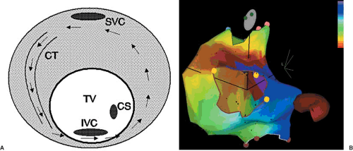
The most common form of atrial flutter is the so-called typical form of atrial flutter. The reentrant circuit involves cranial-caudal conduction over the crista terminalis, continuing across the cavotricuspid isthmus, breaking out onto the interatrial septum and posterior atrial wall, conducting up to the roof of the right atrium anterior to the superior vena cava opening, and then entering the superior end of the crista again. When viewed from the ventricular side of the tricuspid annulus, the reentrant waveform rotates around the tricuspid annulus in a counterclockwise direction. Thus, this common form of typical flutter is sometimes called counterclockwise flutter. Early mapping studies of this type of flutter demonstrated that the wavefront propagated craniocaudally along the lateral right atrium and caudocranially along the septal portion of the right atrium, with slow conduction occurring along the inferior portions of the right atrium (5). This reentrant pathway in the human heart was also described by Feld and colleagues in their report on the use of radiofrequency ablation to interrupt the tachycardia circuit (6). The slow area of conduction in the low right atrium was identified to be the isthmus of atrial myocardium located between the tricuspid valve and the inferior vena cava. Figure 64.1 shows a schematic representation of a typical atrial flutter circuit and an actual electroanatomic map of this type of atrial flutter. Figure 64.2 shows a representative electrocardiogram (ECG) of this type of atrial flutter. Several barriers help to shape this reentrant circuit. The tricuspid valve forms the end of the atrial tissue anteriorly. The crista terminalis laterally form both a barrier and a path of conduction. The inferior vena cava provides the posterior barrier of the cavotricuspid isthmus. Although only one reentrant path is necessary for a tachycardia to exist, often there are two paths forming a figure-of-eight reentry (7). In the case of the typical flutter circuit, the reentrant loop around the tricuspid valve can be accompanied by a lower loop circulating around the inferior vena cava. The common path of the two loops forming the “waist” of the figure-of-eight is the cavotricuspid isthmus. Although less often seen clinically, the same circuits can also rotate in the opposite direction, creating the so-called clockwise typical flutter (8). The two types of circuit rotation result in different atrial activation patterns, generating somewhat different ECG morphologies of the flutter
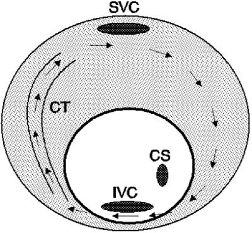
wave. With the typical pattern, atrial activation starts with septal breakout of the waveform emanating from the cavotricuspid isthmus. The remainder of the right and left atria tends to be activated more or less simultaneously. This results in the flutter wave having a superiorly directed vector on the surface ECG. In the less common clockwise version, wavefront breakout occurs at the lateral portion of the tricuspid annulus. It then spreads cranially and then across the right atrial roof before propagating across to the left atrium. A schematic view of the reentrant circuit in the right atrium is shown in Figure 64.3. This propagation pattern generates a more horizontal or inferiorly directed vector that points toward the patient’s left (9). The leftward ECG leads (lead I and lead aVL) generally show a positive flutter wave. Catheter ablation of these
two types of flutter is typically accomplished by interrupting the reentrant pathway within the cavotricuspid isthmus. Radiofrequency lesions are directed at the isthmus near the most inferior portion of the tricuspid annulus. If this is unsuccessful, a more septal line of lesions can also be used (10). More recently, cryoablation catheters using deep freezing as a means of ablating cardiac tissue have been successful in interrupting the flutter circuit (11,12). A possible advantage of the cryothermal approach is the lack of pain perception by the patient during the application of the cryolesion. With either approach, interruption of the flutter circuit acutely is successful more than 90% of the time. There is a recurrence rate of around 10% to 15%, however, due to which a repeat procedure may be needed.
 FIGURE 64.3. Schematic representation of a counterclockwise atrial flutter circuit. The reentrant pathway is essentially the reversal of the clockwise circuit seen in Figure 64.1A. CS, coronary sinus; CT, crista terminalis; IVC, inferior vena cava; SVC, superior vena cava. |
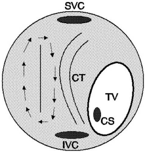
Although the typical form of atrial flutter is the most commonly seen variety, other reentrant circuits can be the basis of an atrial flutter. These are generally referred to as atypical atrial flutters and can have a variety of mechanisms (13). Isolated reports of flutters emanating from the ostial regions of the superior vena cava (14) and reentry around the upper portions of the crista terminalis using conduction gaps in the crista have been documented (15). Probably the next-most-common type of atrial flutter after the typical flutters are those associated with incisional scars due to cardiac surgery, whether for congenital heart disease (16,17) or, more commonly in adults, valvular heart surgery (18). The incisions made to the atria for mitral and tricuspid valve surgery can form a barrier around which the flutter wavefront can circulate. Three sites of incisional scars are commonly seen. The right atrial free wall is a common site for an incision to expose the tricuspid valve as well as the interatrial septum (Fig. 64.4). With the minimally invasive approaches currently used for mitral valve surgery, access to the left atrium is obtained transseptally from the right atrium. Thus, the septal incision can also form a substrate for atrial flutter. Last, incision in the posterior portions of the left atrium, septally or between the two sets of pulmonary veins, may provide the substrate for a reentrant circuit.
Catheter ablation of flutters associated with surgical incisions are more challenging and generally require the use of an electroanatomic mapping system to adequately define the reentrant circuit as well as the optimal sites for ablation. Multiple reentrant circuits may be present such as those related to the incision and those of the more typical type (19).
 FIGURE 64.4. Atrial flutter around an incision. A surgical incision can form the barrier around which the flutter wavefront can circulate. In this schematic diagram, the right atrium is viewed anteriorly, showing the tricuspid valve (TV) pointing to the patient’s left and inferiorly. The right free wall incisional scar forms the barrier around which the reentrant flutter wavefront circulates. Such a reentrant wavefront can readily exist in a dual-loop form with the typical flutter circuit illustrated in Figure 64.1A. CS, coronary sinus; CT, crista terminalis; IVC, inferior vena cava; SVC, superior vena cava. |
Stay updated, free articles. Join our Telegram channel

Full access? Get Clinical Tree


