Angiography of the Aorta and Peripheral Arteries
Michael R. Jaff
John Rundback
Kenneth Rosenfield
Atherosclerosis is a systemic disease that afflicts millions of patients annually in the United States. Historically, most of the clinical focus has been on its coronary artery manifestations, given their frequency and the potentially grave consequences. Although specialists in vascular medicine and vascular surgery have long recognized that peripheral (i.e., extracardiac) arterial occlusive disease may contribute significantly to morbidity and mortality, it is only recently that invasive and interventional cardiologists have become actively involved in its diagnosis and management. To support that involvement, this chapter includes atherosclerotic manifestations in all major arterial territories. It reviews the natural history, clinical presentation, noninvasive diagnostic modalities, and angiographic techniques used in patients with peripheral vascular disease, including aneurysmal disease of the thoracic and abdominal aorta, and atherosclerotic disease of the extracranial carotid arteries, renal arteries, and lower-extremity arteries.
PERIPHERAL IMAGING TECHNIQUES
Aortography and peripheral angiography have a history as long as that of cardiac catheterization. Shortly after W. Forssmann reported the passage of a catheter from his own arm vein into his right atrium in 1929,1 dos Santos and colleagues described their experience in performing abdominal aortography by direct needle puncture.2 Seven years later, Nuvoli performed aortography via direct needle puncture of the ascending aorta.3 Fortunately, these direct access techniques have now been virtually replaced by the percutaneous and direct (see Chapters 6 and 8) techniques for catheter introduction, which form the foundation of modern angiography. In the past decade, major improvements have also been made in noninvasive imaging techniques, so that modalities such as duplex ultrasound, computed tomography (CT), and magnetic resonance angiography (MRA) are now frequently the initial investigations for diagnosis and monitoring of peripheral vascular disease. These noninvasive imaging techniques augment the traditional techniques of catheter-based angiography, facilitating detection of subclinical disease, strategization for interventional procedures, and safe and reliable methods for continued surveillance.
CROSS-SECTIONAL ARTERIAL IMAGING
Contemporary cross-sectional techniques for computed tomographic angiography (CTA) and MRA produce highresolution and reproducibly validated angiographic displays of nearly all peripheral circulatory beds. The use of high magnetic flux imaging as well as regionally specialized algorithms optimizes imaging performance for specific anatomic and pathologic conditions. Unlike traditional catheter-based angiography, CTA and MRA produce multiplanar (orthogonal) images through embedded data acquisition; this allows angiographic evaluation using dedicated workstations to produce images in projections (e.g., axial, sagittal, and curved planar reconstructions) that cannot be obtained by catheter methods (curved planar reformation, or CPR pictures). An evaluation of cross-sectional data sets, often referred to as “raw data,” permits a unique and highly detailed perspective of both vascular and the adjacent structures, which contributes to pathologic diagnosis4 (Figure 19.1).
While noninvasive imaging modalities avoid many of the potential complications of catheter-based angiography, some limitations still exist. CTA is associated with relatively high levels of exposure to ionizing radiation, often exceeding the dose in conventional angiography.5 Consequently, repeated
use of CTA imaging in younger patients may be associated with a mildly increased hazard of subsequent malignancy.6 CTA also requires the administration of iodinated contrast, which allows potential harm in patients with contrast hypersensitivity or impaired renal function. MRA avoids radiation exposure, but is a longer examination, and is thus susceptible to image degradation related to motion artifact. Respiratory and cardiac gated techniques have been applied with some promise for thoracic vascular imaging.7 Patients with permanently implanted ferromagnetic medical devices (e.g., pacemakers or implantable defibrillators) or shrapnel have absolute contraindications for MRA. Notably, most metallic stents are nonferromagnetic or have sufficient implant stability to not preclude MRA8; however, the magnetic susceptibility artifact produced by stents obscures evaluation of the stented vascular segment (Figure 19.2). Finally, the gadolinium chelates administered intravenously in most MRA techniques have been associated with the potential for nephrogenic systemic fibrosis in renally impaired patients (glomerular filtration rate <30 mg/minute).9 Newer MRA protocols are being refined to allow accurate arterial imaging without the administration of gadolinium.10,11 These techniques utilize three-dimensional fast spin-echo acquisition with cardiac gating, with digital subtraction of systolic phase images from the diastolic ones to eliminate venous and background signals; k-space optimization facilitates rapid scanning and enhances contrast resolution.12
use of CTA imaging in younger patients may be associated with a mildly increased hazard of subsequent malignancy.6 CTA also requires the administration of iodinated contrast, which allows potential harm in patients with contrast hypersensitivity or impaired renal function. MRA avoids radiation exposure, but is a longer examination, and is thus susceptible to image degradation related to motion artifact. Respiratory and cardiac gated techniques have been applied with some promise for thoracic vascular imaging.7 Patients with permanently implanted ferromagnetic medical devices (e.g., pacemakers or implantable defibrillators) or shrapnel have absolute contraindications for MRA. Notably, most metallic stents are nonferromagnetic or have sufficient implant stability to not preclude MRA8; however, the magnetic susceptibility artifact produced by stents obscures evaluation of the stented vascular segment (Figure 19.2). Finally, the gadolinium chelates administered intravenously in most MRA techniques have been associated with the potential for nephrogenic systemic fibrosis in renally impaired patients (glomerular filtration rate <30 mg/minute).9 Newer MRA protocols are being refined to allow accurate arterial imaging without the administration of gadolinium.10,11 These techniques utilize three-dimensional fast spin-echo acquisition with cardiac gating, with digital subtraction of systolic phase images from the diastolic ones to eliminate venous and background signals; k-space optimization facilitates rapid scanning and enhances contrast resolution.12
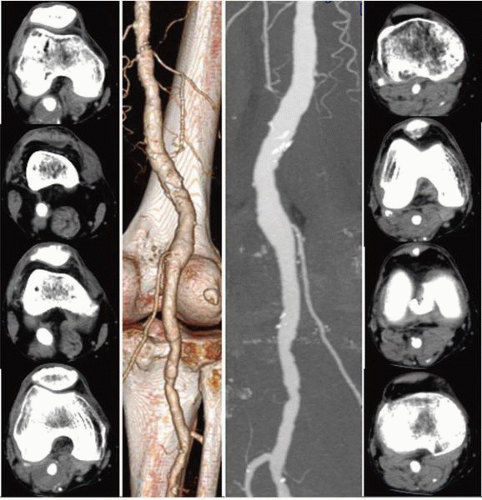 Figure 19.1 Value of cross-sectional images for diagnosis. Surface rendered and maximum intensity pixel images (center panels) in a patient with a popliteal aneurysm shows arterial ectasia but does not demonstrate the full extent of the aneurysm. Source data axial images (outer panels) clearly show the patent lumen surrounded by a large amount of thrombus. For small popliteal artery aneurysms, thrombus imaging is crucial for determining the need and timing for intervention. |
For patients in whom the principal goal is identification of a distal target vessel for bypass or endovascular treatment, two-dimensional time-of-flight (2D-TOF) MRA has an established value and does not require the administration of gadolinium chelates.13
There are numerous MRA sequences with many still evolving. Historically, time-of-flight MRA (TOF-MRA) was the initial approach.14 Two-dimensional TOF detects the inflow of unsaturated protons in the flowing vascular pool against the background tissue, which has been suppressed by the rapid sequences of radiofrequency signals.15 Although still
used on occasion, 2D-TOF has limited spatial resolution and a tendency to overestimate stenosis severity.16 Phase contrast MRA (PC-MRA) represents another bright blood imaging sequence. PC-MRA allows determination of flow direction, although images are substantially degraded by in-line, sluggish, or turbulent flow (and dephasing of spins), with resulting loss of vascular signal.17
used on occasion, 2D-TOF has limited spatial resolution and a tendency to overestimate stenosis severity.16 Phase contrast MRA (PC-MRA) represents another bright blood imaging sequence. PC-MRA allows determination of flow direction, although images are substantially degraded by in-line, sluggish, or turbulent flow (and dephasing of spins), with resulting loss of vascular signal.17
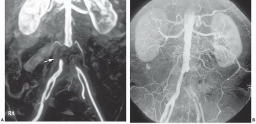 Figure 19.2 Stent artifact on MRI. Gadolinium-enhanced 3D TOF pelvic MRA shows apparent occlusion of both iliac arteries A. A focus of bright signal can be noted at the edge of the stent due to magnetic susceptibility effects related to a ferromagnetic iliac stent on the right side (arrow). Subsequent catheter angiography shows a widely patent right iliac stent B. |
Contrast-enhanced MRA (CE-MRA), utilizing timed intravenous bolus injections of gadolinium chelates, is the predominant MRA imaging sequence. CE-MRA improves the signal-to-noise ratio (SNR), is independent of flow, and has validated excellent correlation with catheter angiography. Since gadolinium is a blood-pool agent, CE-MRA is acquired as steady state images rather than as dynamic sequences. Consequently, contamination by overlying vascular structures and veins may degrade image quality18 (Figure 19.3). To allow dynamic CE-MRA imaging over large vascular fields, multistation MRA or moving-table MRA has been utilized. Multistation MRA requires multiple injections, masking of the venous and parenchymal signal from the initial injection, and the use of high volumes of contrast.19 Moving-table MRA with bolus chasing overcomes some of these limitations by maximizing the data obtained from a single bolus. The rapid transit time from the aorta to the lower limbs is such that venous filling cannot be completely negated,20 although the preliminary application of saturation pulses and the use of venous tourniquets are effective in suppressing venous signal in most instances. The physics of advanced imaging sequences and Fourier transformation techniques are beyond the scope of this chapter. Nevertheless, it can be stated that higher field strength magnets, fat saturation, and improved bolus timing maximize the SNR. Enhanced imaging techniques now allow high-resolution single-breathhold images of the chest and great vessels without the need for gating, and techniques such as time resolved imaging of contrast kinetics (TRICKS) reliably provide sequential flow images comparable to those from conventional angiography.21 Combined first pass (TRICKS) and steady state (3D-TOF) imaging improves diagnostic accuracy.22
Since it was first reported in 1992, CTA has seen several improvements, which have resulted in rapid image acquisition and improved image resolution.23 In particular, the development of multidetector CT (MDCT) has allowed shorter image acquisition time, thinner sections, and improved longitudinal coverage (Figure 19.4). Like in MRA, manually or automatically triggered bolus timing algorithms allow optimal image timing and contrast opacification of the target vascular bed. In comparison to MRA and duplex sonography, CTA for the initial imaging evaluation of peripheral artery disease (PAD) is associated with reduced costs owing to a lesser need for additional imaging.24 Dedicated software or third-party workstations allow detailed image rendering in multiple projections, although an evaluation of the source axial data remains a critical component of image interpretation. Images are generally reconstructed to render longitudinal vessel displays similar to those in conventional angiograms and can
be viewed in multiple projections from a single acquisition. The two major reconstruction protocols produce surface rendered (SR) and maximum intensity pixel (MIP) displays (Figure 19.5). SR images provide a three-dimensional shaded appearance of the arteries with or without background skeletal or soft tissue details. To produce this effect, thresholding is applied wherein only structures with a Hounsfield density above a certain value (i.e., iodinated contrast density) are included in the final image, in a gated fashion; soft tissues and other lower-density images are excluded from the final picture. MIP images display all contiguous uniform density pixels, as in an opacified blood vessel, in a two-dimensional representation. MIP images may also be viewed in any projection, and can in addition be paged through to provide a better evaluation of internal vessel structure. CTA has some notable limitations, predominantly due to its dependency on contrast resolution between opacified vessels and the surrounding tissue. To achieve this contrast differentiation, a high volume (80 to 150 cc) of iodinated contrast delivered through a larger-bore IV at a rate of 3 cc/sec is required. Consequently, CTA has an associated risk of contrast hypersensitivity and contrast-induced nephropathy (CIN), and is precluded in patients with stage 4 or worse chronic kidney disease. In patients with congestive heart failure, impaired venous or arterial transit times, poor peripheral intravenous access, or marked asymmetry in limb flow, inadequate opacification and image degradation may occur. While CTA is highly correlated with conventional angiography for aortoiliac disease, reliability is less in the case of femoropopliteal disease and even more impaired for infrapopliteal disease. In these distributions, the presence of medial calcification reduces accurate visualization of the arterial lumen, and the thresholding effect of SR-CTA prevents differentiation between calcium and contrast. As a result, a densely calcified and highly stenotic vessel may appear to have a normal caliber on SRCTA. Newer reconstruction techniques have been developed to overcome the problem associated with evaluating calcified vessels. Most notably, curved planar reconstructions (CPR) produce midline images from the composite arterial dataset, thus improving lumen imaging and stenosis evaluation (Figure 19.5). Even though this technique improves the outcomes, inaccurate assessment of calcified arteries still remains a major drawback of CTA. The strengths and weakness of each technique are listed in Table 19.1.
be viewed in multiple projections from a single acquisition. The two major reconstruction protocols produce surface rendered (SR) and maximum intensity pixel (MIP) displays (Figure 19.5). SR images provide a three-dimensional shaded appearance of the arteries with or without background skeletal or soft tissue details. To produce this effect, thresholding is applied wherein only structures with a Hounsfield density above a certain value (i.e., iodinated contrast density) are included in the final image, in a gated fashion; soft tissues and other lower-density images are excluded from the final picture. MIP images display all contiguous uniform density pixels, as in an opacified blood vessel, in a two-dimensional representation. MIP images may also be viewed in any projection, and can in addition be paged through to provide a better evaluation of internal vessel structure. CTA has some notable limitations, predominantly due to its dependency on contrast resolution between opacified vessels and the surrounding tissue. To achieve this contrast differentiation, a high volume (80 to 150 cc) of iodinated contrast delivered through a larger-bore IV at a rate of 3 cc/sec is required. Consequently, CTA has an associated risk of contrast hypersensitivity and contrast-induced nephropathy (CIN), and is precluded in patients with stage 4 or worse chronic kidney disease. In patients with congestive heart failure, impaired venous or arterial transit times, poor peripheral intravenous access, or marked asymmetry in limb flow, inadequate opacification and image degradation may occur. While CTA is highly correlated with conventional angiography for aortoiliac disease, reliability is less in the case of femoropopliteal disease and even more impaired for infrapopliteal disease. In these distributions, the presence of medial calcification reduces accurate visualization of the arterial lumen, and the thresholding effect of SR-CTA prevents differentiation between calcium and contrast. As a result, a densely calcified and highly stenotic vessel may appear to have a normal caliber on SRCTA. Newer reconstruction techniques have been developed to overcome the problem associated with evaluating calcified vessels. Most notably, curved planar reconstructions (CPR) produce midline images from the composite arterial dataset, thus improving lumen imaging and stenosis evaluation (Figure 19.5). Even though this technique improves the outcomes, inaccurate assessment of calcified arteries still remains a major drawback of CTA. The strengths and weakness of each technique are listed in Table 19.1.
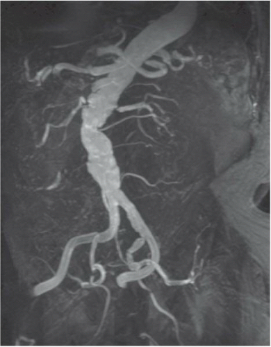 Figure 19.3 Contrast-enhanced MRA of the aorta demonstrating aortic tortuosity with evidence of mural thrombus. Both the right and left renal arteries demonstrate high-grade stenoses at their origin. |
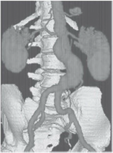 Figure 19.4 Three-dimensional computed tomographic angiography (CTA) of an infrarenal aortic aneurysm, demonstrating the application of novel imaging protocols in current vascular medicine practice. |
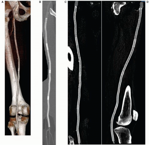 Figure 19.5 Surface rendered (SR, A), maximum intensity pixel (MIP, B), and curved planar reconstruction (CPR, C, D) of a left femoral stent. Note that the thresholding effect of the SR image limits evaluation of the underlying arterial lumen. Similarly, the MIP image clearly shows the stents and areas of stent overlap, but does not provide a clear assessment of stent patency. The CPR image, which displays center line vessel data, shows the stent to be free of any stenosis. |
RADIOGRAPHIC IMAGING
Catheter-based angiography has equally undergone a new level of complexity and sophistication and, at this writing, remains the gold standard for diagnosis of arterial disease. As with cardiac angiography (Chapter 2), the techniques of vascular angiography are predicated on maximizing benefit for the patient while minimizing the associated risk. These principles are summarized in the recently updated consensus conference guidelines regarding the clinical competency required for the diagnosis and management of peripheral vascular diseases.25
Principles of vascular angiography may be divided into general considerations common to all vascular territories and specific considerations relating to individual vascular beds. General considerations include techniques of arterial access, radiographic equipment, catheter design and use, anticoagulation, and contrast selection. Specific principles, discussed in their relevant sections, include the choice of arterial access,
catheter selection, optimal angulation, adjunctive methods of evaluation (intravascular ultrasound [IVUS], translesional pressure gradient measurement, and so on), and classification of angiographic findings.
catheter selection, optimal angulation, adjunctive methods of evaluation (intravascular ultrasound [IVUS], translesional pressure gradient measurement, and so on), and classification of angiographic findings.
Table 19.1 Relative Advantages and Disadvantages of CTA and MRA | |||||||||||||||||||||||||||||||||||||||
|---|---|---|---|---|---|---|---|---|---|---|---|---|---|---|---|---|---|---|---|---|---|---|---|---|---|---|---|---|---|---|---|---|---|---|---|---|---|---|---|
| |||||||||||||||||||||||||||||||||||||||
VASCULAR ACCESS
Although arterial access has been discussed previously (Chapters 6, 7, and 8), its importance in achieving a safe, complication-free procedure cannot be overstated, particularly in patients with known peripheral vascular disease. Deciding on the appropriate site of access for peripheral arteriography is a preprocedural decision of utmost importance, analogous to planning a surgical incision. Optimal access reduces the likelihood of complications and shortens the duration of the procedure. The most favorable site of access is determined based on the clinical history, physical examination, and noninvasive studies (e.g., duplex ultrasonography, MRA, or CTA). The most commonly used sites remain the common femoral and brachial arteries. If the femoral pulse is diminished or absent (e.g., owing to occlusion more proximally), one of several methods may be used to facilitate successful entry of the artery.26,27 We strongly recommend confirming the site of femoral access by fluoroscopy in all patients, particularly in those with ambiguous surface landmarks (see Chapter 6). For retrograde femoral access, a skin mark at the lower end of the femoral head is generally selected to allow entry into the femoral artery in the middle of the femoral head; this facilitates counter-pressure for successful manual hemostasis after catheter removal and assures that puncture remains below the inguinal ligament. In situations in which an initial high puncture is noted (above an imaginary line connecting the anterior inferior iliac spine and pubic symphysis, denoting the position of the inguinal ligament), removal of the needle and repuncture is recommended. Arterial calcification, which is frequently present in diseased arteries, can also aid as a fluoroscopic target. Ultrasound guidance, and road mapping of a contrast injection performed via a catheter positioned in the distal aorta from the contralateral groin, may also be helpful.
Although many operators use crossover techniques from the contralateral femoral artery, antegrade puncture of the ipsilateral common femoral artery (CFA) is widely used to approach femoral, popliteal, or infrapopliteal disease. Antegrade access is considered more challenging technically and limits angiography to the ipsilateral leg, but it offers a more stable platform for intervention. The patient’s orientation is reversed in such a way that the feet are placed at the head of the gantry, allowing maximal mobility of the image intensifier around the lower limbs. As in retrograde access, the desired site of entry is in the middle of the CFA below the inguinal ligament, but given the different angulation, the skin puncture is made at or above the top of the femoral head28 (Figure 19.6). A 9 cm needle is frequently required, as compared with the standard 7 cm needle used for retrograde access. A less acute needle angle, generally <45°, facilitates catheter and sheath insertion by avoiding the kinking associated with a steeper-angled entry. Arterial puncture should be performed under fluoroscopic guidance aiming for the mid or upper portion of the femoral head.
Aids to antegrade access include arterial calcification or prior studies (angio, CTA, or MRA) that define the bifurcation of the CFA in relation to the femoral head. In cases with a known high CFA bifurcation, the antegrade stick should be modified accordingly.
Aids to antegrade access include arterial calcification or prior studies (angio, CTA, or MRA) that define the bifurcation of the CFA in relation to the femoral head. In cases with a known high CFA bifurcation, the antegrade stick should be modified accordingly.
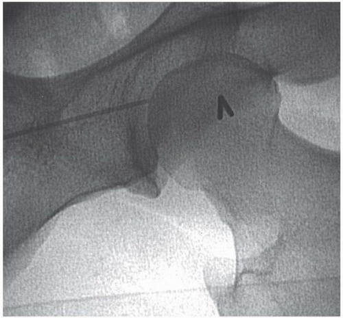 Figure 19.6 Antegrade femoral artery puncture. The skin nick at the top of the femoral head (needle), with ideal entry at the middle of the common femoral artery at an angle of <45°. |
Having achieved arterial puncture, a 0.035 inch wire is advanced under fluoroscopic guidance into the proximal SFA or PFA. The wires that we recommend include a Bentson wire (with a 15 cm floppy atraumatic tip), a Wholey wire (which provides a gentle steerable tip) or an angled Glidewire (which gives easy passage into the femoral circulation but must be used with care as it may track subintimally or be skeletonized by the sharp edge of the access needle). For scarred groins from prior surgery, the use of nitinol core wires can be useful to prevent kinking. We recommend use of a 5F sheath until the site of arteriotomy and procedural requirement have been confirmed. To confirm the site of antegrade access, angiography with 30° to 50° of ipsilateral oblique angulation will define the arteriotomy site in relation to the common femoral bifurcation. Anticoagulation agent should be administered once the correct position of the access point has been confirmed and if intervention is anticipated; anticoagulation is not routinely used in purely diagnostic angiography. Extra care should be taken to remove the antegrade sheath promptly following the procedure to minimize complications. It is our practice to consider reversing anticoagulation to facilitate immediate sheath removal in the catheterization laboratory, although the availability of closure devices has reduced the need to reverse anticoagulation.
Great care should be exercised while advancing and manipulating catheters and guidewires in the severely diseased peripheral circulation to reduce the chance of embolization related to the traumatic disruption of cholesterol-rich atherosclerotic plaque. This rare but devastating complication of arteriography may lead to livedo reticularis, hypertension, renal failure, stroke, or potential death (see Chapter 4). Although there are no proven therapies effective in the management of this dreadful complication, prostanoids (e.g., PGE1, PGI2) may serve a palliative role in those cases in which it occurs.29,30
RADIOLOGIC EQUIPMENT
As in cardiac catheterization, optimal imaging requires a radiographic gantry capable of axial and sagittal orientation with sufficient mobility to allow imaging of all vascular beds. To capture the larger regions of interest (e.g., the entire aortic arch, the pelvic vasculature, or both legs) a large-field (14 inch or 36 cm) image intensifier is recommended. Widespread application of digital imaging has facilitated contrast enhancement and noise reduction, providing superior angiographic results. Digital subtraction angiography (DSA) and road mapping are two techniques commonly used in peripheral angiography and intervention. In DSA, subtraction of a precontrast mask suppresses interfering structures from subsequent projections, thereby enhancing arterial filling and masking fixed structures (bone, calcifications, soft tissue, and air densities). This allows the use of lower doses of iodinated contrast or use of noniodinated contrast including carbon dioxide or gadolinium31,32 (Figure 19.7A, B).
Further postprocessing features include contrast inversion (changing white arterial structures to appear black), magnification, pixel shifting, picture integration (landmarking), contour enhancement, image stacking, and three-dimensional reconstruction of the subtracted image.33, 34, 35, 36, 37 Quantitative analysis may be used to assess vessel diameters and lengths, degree of luminal narrowing, and blood flow velocity.38 Another useful technique used in DSA is road mapping. This technique is used for selective catheterization and is a useful aid for visualization of a moving catheter. Prior to moving the catheter, a small amount of contrast medium is injected. The image with filled vessels is stored in memory as a mask (a road map along which the catheter is to be moved). This mask is then subtracted from the fluoroscopic images that follow, which will display both the vessels and the catheter with its tip. Some newer angiographic equipment allows the creation of a “smart mask” from prior angiograms which can be used to generate a roadmap image. Although it is not used in cardiac work (where cardiac motion precludes acquiring a suitable “mask” image), DSA is of great value in peripheral angiography as it reduces contrast volume, procedure time, and radiation exposure.
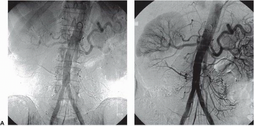 Figure 19.7 A. Normal abdominal aortogram using iodinated contrast material obtained by digital imaging technique. B. Same imaging data, but with enhancement of contrast-filled vessels obtained by the subtraction of all background densities (bones, soft tissue, gas) as recorded on a mask immediately prior to contrast injection. |
CATHETERS AND GUIDEWIRES
Just as there are a wide range of cardiac catheters and guidewires, vascular angiography and intervention have a wide range of tools available to meet different anatomic challenges. In addition to standard, thin-walled 18 gauge needles that will accommodate a 0.038 inch wire, micropuncture (e.g., 21 gauge) needle sets are available that allow conversion to a nonstandard (e.g., 0.035 inch) guidewire in situations where there is a high risk of bleeding or after unsuccessful needle puncture attempts.
Most peripheral guidewires are made of a stainless steel coil surrounding a tapered inner core that runs the length of the wire for additional strength. A central safety wire filament is incorporated to prevent separation if ever the wire coil were to fracture. Standard wires vary in diameter from 0.012 to 0.052 inch, with 0.035 and 0.038 inch being the most commonly used sizes. The length of most standard wires is between 100 and 180 cm; longer exchange-length guidewires (measuring 260 to 300 cm) permit keeping the tip of the wire at a selected position during catheter exchange. Tip configurations include straight tip, angled tip, and J-shaped tip. Special features may include the ability to move the wire’s inner core to vary the length of the floppy tip, deflect the wire tip, or transmit torque from the shaft to the tip so that it can be steered within the vascular tree. Varying degrees of shaft stiffness (e.g., extra-support wires) allow advancement of stiff devices through tortuous vessels. Low-friction wires with a hydrophilic coating (glide wires) have revolutionized peripheral work and made it possible to perform superselective catheterization and traverse complex stenoses and long occlusions.
Peripheral angiographic catheters are constructed of polyurethane, polyethylene, Teflon, or nylon with a wire braid in the wall of the catheter to impart torque ability. An ideal catheter has good memory, is nonthrombogenic, has sufficient torque control to facilitate rotational positions, can accommodate high-pressure injection, and tracks well (frequently aided by hydrophilic polymer coating). Catheters vary in French size, length, and hole pattern—a single end hole for selective injections, both end and side holes, or a blocked end with only side holes. For catheters designed to be positioned in the abdominal aorta, a length of 60 to 80 cm is sufficient; in the thoracic or carotid areas, a length of 100 to 120 cm (similar to those of left heart catheters) may be required. The most common diagnostic catheter sizes are 4F to 7F.
Several catheter shapes have been designed, and each ultimately determines a specific function (Figure 19.8). They fall into the following general types:
Straight catheters with multiple side ports that are used for rapid injection into large vessels and for exchange.
Pigtail or tennis-racket catheters that are used for nonselective angiography in large vessels (i.e., aorta, pulmonary artery, or cardiac chambers). Multiple side holes along the distal shaft allow rapid delivery of contrast instead of a single forceful jet that could cause catheter whipping or subintimal dissection as might be seen with contrast exiting the end-hole alone.
Simple curved catheters (e.g., Berenstein, Cobra, Headhunter) that are used for vessel selection.
Complex reverse-curve catheters (e.g., Simmons, side-winder, SOS-OMNI) that are used for selective catheterization of certain aortic branches.
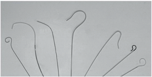 Figure 19.8 Peripheral angiographic catheters. Left to right. Pigtail, Cobra, multipurpose, Headhunter, Simmons, SOS-omni, tennis racket. |
CCONTRAST AGENTS
The principles of contrast agents are similar for peripheral angiography as for coronary angiography (Chapter 2). In general, high-osmolar contrast materials are avoided as they are associated with increased side effects (nausea, vomiting, light-headedness, local pain during peripheral injection), all of which reduce patient tolerance.39 Low-osmolar or iso-osmolar contrast delivers less osmotic load, resulting in reduced intravascular volume augmentation. Although their use has traditionally been confined to certain high-risk patient groups, they have more recently become standard in all catheterization laboratories.
CIN (see Chapter 4) has become one of the most common complications of angiography, accounting for a 14.5% incidence of acute renal failure post-angiography, and making it the third most common cause of new onset renal failure in hospitalized patients.40 CIN is particularly prevalent in peripheral angiography owing to the large volumes of contrast required and the high incidence of comorbidities such as baseline renal dysfunction, diabetes, hypertension, and renal artery atherosclerosis.41 Aggressive prehydration, particularly with isotonic (0.9%) rather than hypotonic (0.45%) saline, reduces CIN, especially in high-risk patients.42 Use of iso-osmolar contrast agents (e.g., iodixanol) might decrease the incidence of CIN,43 although controversies still exist regarding the added benefit of iso-osmolar contrast agents when compared with low-osmolar contrast agents (Chapters 2 and 4). Attempts to target the final pathway of free-radical injury have focused on the use of the antioxidant acetylcysteine.44, 45, 46, 47, 48 The results, however, have been conflicting, and as of today the use of acetylcysteine is no longer recommended by the current guidelines. Benefits with periprocedural infusion of sodium bicarbonate have recently been reported.49 Unfortunately, also in the case of bicarbonate, available data do not support unequivocally its use as a replacement for aggressive hydration with isotonic normal saline (Chapter 4).
Preventative methods for CIN have focused on the development of non-nephrotoxic contrast agents. Two such agents have now emerged as alternatives in patients with renal dysfunction or a history of contrast allergy. Carbon dioxide (CO2) as a contrast agent has been used extensively in many vascular beds.50, 51, 52, 53, 54 Its primary advantage is that it obviates any risk of allergic reaction or nephrotoxicity.55 Its application is limited to arteries below the diaphragm to minimize the risk of cerebral embolization, and digital subtraction equipment is required. Another agent gadolinium (gadopentetate dimeglumine) has traditionally been used with magnetic resonance imaging, but can also be applied to catheter-based imaging.56, 57, 58 Like CO2, it is relatively nontoxic, although the maximal dose is limited to 0.4 mmol/kg (approximately 60 mL). Gadolinium should not be used in patients with grade 4 chronic kidney disease owing to the risk of nephrogenic systemic fibrosis.
In patients with renal insufficiency, several strategies have been deployed with varying degree of success to reduce the risk of CIN.59 The primary preventive measures include limiting the contrast dose and vigorous preprocedural hydration. The addition of bicarbonate saline solutions to the hydrational regimen has been demonstrated to help prevent CIN in multiple observational studies,60 although this has been disputed in one, more recent, trial in which bicarbonate infusions increased risk.61 As mentioned above, owing to the inconsistency in results, the use of oral or intravenous N-acetylcysteine prior to angiography is no longer recommended.62 Finally, targeted renal therapy using direct intrarenal infusion of fenoldopan via a specialized two-prong catheter (Benephit, Angiodynamics) holds promise for lowering CIN but requires enlargement of the femoral access sheath or a second arterial puncture.63
Beyond these general peripheral imaging techniques, there are a number of important considerations relating to each portion of the arterial tree. In this and subsequent chapters relating to peripheral circulation, we will review the territories in a head-to-foot sequence.
THORACIC AORTA
Anatomy
The aortic valve is composed of three leaflets that form the three sinuses of Valsalva: right, left, and posterior.64 The ascending aorta itself begins just beyond the sinus segment, and courses in a mostly anterior-posterior direction. The diameter of the ascending aorta varies between 2.2 and 3.8 cm in middle-aged adults and increases slightly with advancing age.65 After it passes over the main pulmonary artery and left mainstem bronchus, the aorta gives rise to the brachiocephalic trunk and then courses posteriorly and leftward in front of the trachea. It then gives rise to the remaining arch vessels—the left common carotid, and left subclavian arteries—from its upper surface. (Figure 19.9A)
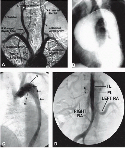 Figure 19.9 A. Normal ascending and arch aortogram with great vessels. B. Ascending aortic aneurysm owing to cystic medial degeneration. C. Stanford type A aortic dissection following aortic valve replacement. The intimal dissection flap (arrows) separates the contrast-filled true lumen (TL) from the false lumen (FL) that compromises the TL as it proceeds distally. D. The dissection extending into the abdominal aorta with origination of the left renal artery from the FL and TL supplying the right renal artery. |
Distal to the origin of the left subclavian artery, the aorta narrows slightly at the site of the isthmus where the ligamentum arteriosum (the remnant of the fetal ductus arteriosus) tethers the aorta to the left pulmonary artery. Just distally to this point, a fusiform dilatation, called the aortic spindle, may occur. The descending aorta then continues anterior to the spine, with a diameter of approximately 2.5 cm. Vessels deriving from the descending portion of the aorta are nine pairs of posterior intercostal arteries (levels T3 to T11). The first and second posterior intercostal arteries are supplied by the superior intercostal artery, which is a branch of the subclavian artery. At the level of the fourth to sixth thoracic vertebrae, anteriorly directed bronchial arteries come off to supply each lung.
Disorders of the Thoracic Aorta
Aortic Coarctation
Coarctation of the aorta (see also Chapter 35) occurs in 0.02% to 0.06% of the population and may be associated with bicuspid aortic valve (33% of cases), patent ductus arteriosus, ventricular septal defect, or the Turner syndrome.66 To bypass the resulting bandlike narrowing of the aorta, collateral flow occurs retrograde into the posterior intercostal branches of the descending aorta. The resultant enlargement and tortuosity of these intercostal arteries are responsible for the “rib notching” seen in chest radiographs.
The classical findings by aortography or MRA are of a high-grade, discrete narrowing of the aorta at the level of the isthmus, with associated dilatation of the ascending aorta and enlargement of the internal thoracic and intercostal arteries.67 Aortography assumes a significant role in differentiating the wide variety of abnormal patterns, including complete aortic interruption, hypoplastic aorta, and the most common type—a stenosis at the site of the isthmus, distal to the origin of the left subclavian artery. Both AP and lateral (right anterior oblique [RAO]/left anterior oblique [LAO]) aortography should be initially undertaken, with contrast injection performed proximal to the presumed site of coarctation using either large-film or cineangiographic technique. When attempting to traverse the site of narrowing in retrograde fashion, care must be taken to avoid inadvertent perforation of the thin-walled poststenotic segment. Entry to the prestenotic aorta from the brachial or axillary arteries may hence be preferred.
Patent Ductus Arteriosus
The prevalence of patent ductus arteriosus is 1/5,500 in children below 14 years of age.68 Selective aortic angiography is sensitive in demonstrating small shunts and surpasses the sensitivity of right heart catheterization with stepwise oximetry (see also Chapters 12, 35, and 45).
Aortic Aneurysms
Thoracic aortic aneurysms (TAAs) and pseudoaneurysms may have various causes, including those that are degenerative, atherosclerosis-related, or congenital (aneurysms of the Valsalva sinus); other causes include trauma, infection (syphilitic, bacterial), cystic medial degeneration, connective tissue disorders, and vasculitic and chronic dissection. Degenerative aneurysms involving the descending aorta account for approximately 75% of TAAs.69,70 Cystic medial degeneration (as seen in the Marfan syndrome) may also result in aneurysms of the ascending aorta71 (Figure 19.9B). Aneurysms caused by blunt or penetrating trauma often involve the proximal descending thoracic aorta where the mobile arch segment joins the descending segment fixed to the spine.72, 73, 74 These may present as pseudoaneurysms—contained ruptures that lack intimal and medial components and are contained only by adventitia and periaortic tissue.
The natural history of TAAs is poorly understood as compared with the extensive data available on untreated infrarenal abdominal aortic aneurysms (AAA).75 Many patients with TAAs are asymptomatic at the time of diagnosis, with the aneurysm incidentally detected during testing for an unrelated disorder. Thoracic aneurysms appear to enlarge at a more rapid rate than that observed in abdominal aneurysms (0.42 versus 0.28 cm/year), and aneurysms larger than 5 to 6 cm in diameter enlarge even faster and have a higher likelihood of rupture.76,77 The cumulative 5-year risk of rupture is increased fivefold in aneurysms ≥6 cm in diameter. Symptoms tend to develop late in the course of the enlargement of the aorta and are usually related to impingement on adjacent structures. In addition to presenting with catastrophic rupture, patients with TAA may report dyspnea, hoarseness, dysphagia, stridor, and plethora with edema from superior vena cava compression. Neck or jaw pain may also be present in patients with aneurysms of the aortic arch. Dilatation of the aortic valve annulus and aortic valve may produce aortic regurgitation and congestive heart failure. Aneurysms of the descending thoracic aorta may produce pleuritic leftsided or interscapular pain, whereas thoracoabdominal aortic aneurysms may induce complaints of abdominal pain and left shoulder discomfort from irritation of the left hemidiaphragm.
The primary treatment for TAAs is surgical repair when the diameter reaches more than 5 to 6 cm or symptoms develop.78 The standard procedure is to use a Dacron graft to replace the diseased segment. In most patients undergoing elective thoracic aorta surgical repair, aortography is required to provide information about the location of the aneurysm and its relationship to major aortic branches in the chest and abdomen. Optimal surgical approaches, as well as operative risks, are best defined by imaging the coronary, brachiocephalic, visceral, and renal arteries during injections. Stent graft devices have been successfully used as an alternative to surgical grafting for both thoracic and aortic degenerative TAAs and posttraumatic descending TAAs.79, 80, 81 Although early experience has been plagued by incomplete aneurysm thrombosis, graft leak, and failure, advances in the technology have rapidly expanded the role of endovascular stent grafts for TAAs82 (Chapter 37).
Aortic Dissection
Aortic dissection is a longitudinal cleavage of the aortic media by a dissecting column of blood.83 An intimal tear allows the passage of blood into the aortic wall, separating the inner and outer layers of the aortic wall and creating a “doublebarrel lumen”.84 Men are affected about twice as frequently as women.85 Most patients are between 50 and 70 years of age and have arterial hypertension.86 Other risk factors include cystic medial degeneration,87 Marfan syndrome,88 bicuspid aortic valve, aortic coarctation, blunt trauma, pregnancy,89,90 connective tissue disorders, and thoracic aorta operative procedures.91 The dissection may extend proximally from its origin to the aortic annulus, or distally to involve the entire
length of the aorta and any or all of its major branches, until terminated by an aortic branch or atherosclerotic plaque. Associated peripheral and visceral patterns of arterial obstructions may be owing to direct extension of the dissection plane into the affected arterial orifice (static dissection) or compromise of the visceral artery origin by the expanded false lumen (dynamic dissection).92
length of the aorta and any or all of its major branches, until terminated by an aortic branch or atherosclerotic plaque. Associated peripheral and visceral patterns of arterial obstructions may be owing to direct extension of the dissection plane into the affected arterial orifice (static dissection) or compromise of the visceral artery origin by the expanded false lumen (dynamic dissection).92
Dissection is usually heralded by the sudden onset of excruciating pain described as tearing, throbbing, lacerating, ripping, or burning in the anterior chest, neck, or intrascapular region.93 Similar pain may occur with rupture or sudden expansion of a chronic dissection. If the acute dissection results in compression of aortic branches, symptoms and signs of acute myocardial infarction,94,95 stroke or TIA, paraparesis,96 mesenteric ischemia, renal failure,97 paraplegia, and extremity ischemia98 may result. Most patients with ascending aortic extension who are treated medically die within 3 months, usually from dissection into the pericardium, mediastinum, or pleural cavity.
Once considered the gold standard for diagnosis of aortic dissection, aortography (which has a sensitivity of 80% and specificity of 95%) has largely been replaced by CT, MRA, and transesophageal echocardiography99 (TEE). Visualization of an intimal flap is the only direct aortographic sign that is pathognomonic of dissection. This occurs frequently in association with delayed or sluggish filling of a second lumen, although about 20% of patients with aortic dissection have only one visible aortic channel. The presence of a false lumen may still be suspected, however, if that single channel shows evidence of diminished caliber and absent branching owing either to extrinsic compression by a hematoma in the false lumen or to intrinsic luminal collapse consequent to loss of wall elastin.92 The false lumen of an aortic dissection is distinguished angiographically by its anterolateral ascending and posterolateral descending position, differential reduced flow, and a generally larger caliber than that of the true lumen. Beyond documenting the dissection, aortography provides information about aortic insufficiency and branch vessel or coronary artery involvement, particularly in cases where CT or MRI findings are equivocal and there is a strong clinical suspicion of aortic dissection.100
Stay updated, free articles. Join our Telegram channel

Full access? Get Clinical Tree


