Peripheral angiographic suites have evolved over the last two decades to contain a number of features that are important in performing high-quality peripheral vascular angiography and intervention. Since most operators are familiar with the basic workings of radiographic imaging systems, the purpose of this chapter will be to outline these unique features. In addition, we will provide an overview of the most commonly used equipment during peripheral diagnostic and interventional studies and describe some of the fundamental principles involved in these procedures.
RADIOGRAPHIC IMAGING
The interactive components of a radiographic imaging system are shown in Figure 6.1.
Image Intensifier
In most contemporary peripheral labs, the diameter of the image intensifier is at least 15″, providing a large field of view. This is particularly important when imaging the aorta or lower extremities. The smaller image intensifier in most cardiac catheterization laboratories (i.e., 9″) is adequate for diagnostic angiography and intervention of the carotid, vertebral, subclavian, renal, and iliac arteries.
Examination Console
During peripheral angiography, a variety of settings (i.e., kVp, mA, frames/sec) will automatically vary depending on the vascular territory of interest. These territories are usually divided as follows: cerebral, thorax, abdomen, upper extremity, and lower extremity. The tube kilovoltage will be set highest for cerebral and abdominal angiography and lowest for angiography of the extremities, with the thorax having an intermediate setting. Frame rates for peripheral angiography are generally 2 to 3 per second, but this can be adjusted for specific circumstances (e.g., increased for angiography with gadolinium contrast or decreased for venous studies in which the cineangiographic runs are long). These vascular package options can be found in the tableside or control room examination console that programs the x-ray generator.
Digital Subtraction Angiography versus Cineangiography
Cineangiography simply takes multiple x-ray pictures of the contrast-filled vessel as well as the surrounding tissue (Fig. 6.2A). For rapidly moving structures with a radiolucent background, such as the coronary arteries moving with the beating heart, this 15- to 30-frames/sec imaging modality is ideal (1).
For static vascular structures that are surrounded by radiodense structures (e.g., bone), digital subtraction angiography (DSA) is the ideal imaging modality (2). With this technique, the initial images obtained when stepping on the x-ray pedal are used to generate the baseline image from which all radio-opaque structures are subtracted. Subsequent images obtained following contrast injection will generate the subtracted images and demonstrate only the contrast-filled vascular structures (Fig. 6.2B).
This imaging modality requires that the patient does not move during image acquisition. In vascular territories where the vessels may move during respiration or swallowing (e.g., carotid, vertebral, abdomen, pelvis), the patient must also suspend these activities during image acquisition.
Trace-Subtract Fluoroscopy or “Road Mapping”
Trace-subtract fluoroscopy is the fluoroscopic equivalent of DSA. Like DSA, the initial few seconds of this mode are used to obtain a fluoroscopic image that is then subtracted (2). Once the subtracted image is seen on the screen, contrast is injected to completely fill the vessel. The pedal is then released and the subtracted image with the contrast-filled vessel remains on the screen (Fig. 6.3A). In contrast to DSA, the contrast-filled vessel will appear white as opposed to black. Subsequent activation of the fluoroscopy pedal allows visualization of catheters, wires, and interventional equipment superimposed on the saved image of the contrast-filled vessel (Fig. 6.3B). When used correctly, this technique can improve the safety of various maneuvers (e.g., advancement of wires and catheters) and help to minimize contrast usage. For optimal results, the patient must remain perfectly still between the time of contrast injection and completion of any intended maneuver.
“Road Mask” Function
A “road mask” may be generated from a DSA acquisition by selecting the single frame of the acquisition that provides optimal filling of the vascular structures of interest and activating this function, generating a vascular mask against which further interventional manipulations can be visualized (Fig. 6.4). This function provides a similar utility to the road mapping function described previously. The major difference between these two functions is that road mapping is best suited to situations where the vascular region of interest takes a prolonged time to fill with contrast, whereas the road mask function is optimal where the vascular region of interest is filled with contrast during a single frame. Both of these functions serve to minimize contrast dye loads during complicated procedures and can improve the safety of manipulations in the vascular tree.
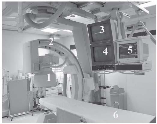
Figure 6.1 • Peripheral angiographic suite. (1) 15″ Image intensifier; (2) multiplane C-arm mounted on overhead track; (3) saved image monitor; (4) image monitor; (5) hemodynamic monitor; (6) long patient bed.
Leg Imaging Capability
The ability to perform lower extremity angiography requires that the image intensifier be able to travel on an overhead track to the patient’s feet. In addition, the table should be sufficiently long to provide working space caudal to the feet since the image intensifier is placed over the legs, thereby eliminating the usual workspace. Long wires (260 to 300 cm) are frequently used so it is important to have plenty of workspace.
There are two fundamental approaches to imaging the lower extremities: interactive mode versus stepped mode with multiple injections. When performing a “runoff” of the leg’s arterial system, traditional practice has been to obtain sequential stepped static angiographic images (i.e., aortoiliac, femoral–popliteal, anterior tibial/posterior tibial/peroneal, and foot) using bolus contrast injections. This can be time-consuming and requires selective cannulation of the ipsilateral external iliac or common femoral arteries. The advantage of this method is that image quality is usually superior, and the ability to alter the angulation of the image acquisition at different locations along the level of the lower extremity can help with vessel visualization, particularly at bifurcation points or where the vessels overly bone.
The interactive mode permits complete imaging of one or both lower extremities with a single bolus given in the ipsilateral external iliac artery or distal abdominal aorta, respectively. The first step is to engage the interactive mode in the control room and establish the beginning and end positions of the table. The bolus is then given, cineangiography is simultaneously commenced, and the bolus is chased by moving the table proximally relative to the image intensifier. The table is then automatically brought back to the starting position and a “dry” cineangiographic run is performed at the same table movement rate. The latter images are used to subtract from the initial contrast-containing images. Digital subtraction images are then obtained from the interactive run and stored. Currently, it is not possible to obtain new DSA images from the interactive run once the case has been transferred from the local storage. Problems arise if a patient has trouble holding still for the 1 to 2 minutes that it takes to complete an interactive run. Additionally, severe stenosis or occlusion in one extremity often results in sufficiently unequal rates of contrast runoff in both extremities that the operator needs to prioritize the leg of interest and compromise on the image quality from the contralateral leg.
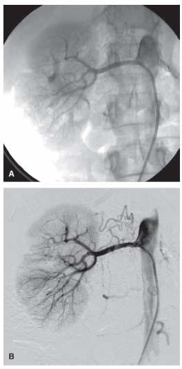
Figure 6.2 • A: Cineangiogram of right renal artery showing vascular and surrounding structures. B: Digital subtraction angiogram of right renal artery showing vascular structures with background subtracted.
Minimizing Radiation Exposure
Peripheral vascular interventions can be very long and involve significant radiation exposure for the operator, the laboratory staff, and the patient. For the operator, maximizing the distance from the source of radiation is a fundamental principle. Wearing an appropriate “lead apron” that is checked annually for its integrity, maximizing shielding (e.g., screens, acrylic leaded shields, thyroid collars, lead glasses), collimating the image field when possible, and using low-dose pulse fluoroscopy are additional important elements in minimizing radiation exposure. Finally, consistently wearing radiation badges that monitor radiation exposure is required so that appropriate investigation of high readings can occur in an expeditious manner, and corrective actions can be instituted if required.
ARTERIAL ACCESS
One of the first steps of any endovascular procedure is determining the most appropriate site for arterial access (3,4).
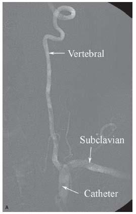
Figure 6.3 • A: Trace-subtract fluoroscopic image of left vertebral artery. Note that vascular structures appear white with this fluoroscopic technique. B: Trace- subtract fluoroscopic image of intracerebral portion of the left vertebral and basilar arteries demonstrating the usefulness of this technique for wiring vessels and positioning equipment.
Common Femoral Artery
This is the most common access site used for peripheral diagnostic angiography and intervention. The common femoral artery (CFA) is centrally located and all vascular arterial systems can be reached barring occlusive and tortuous peripheral vascular disease. The advantage of this access site is the size of the CFA, which can accommodate sheath sizes of 12 to 14 Fr. with minimal risk for ischemia. Most equipment has been developed for the femoral approach and the femoral artery approach also provides greater distance from the x-ray source and a more spacious workplace compared with the arm. On the other hand, CFA access is associated with an increased bleeding risk and delayed ambulation (5,6).
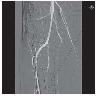
Figure 6.4 • Road mask image generated from digital subtraction angiogram of popliteal artery and proximal portion of tibial vessels.
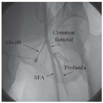
Figure 6.5 • Common femoral artery (CFA) angiogram demonstrating correct position of CFA sheath proximal to the CFA bifurcation at the level of the middle of the femoral head. SFA, superfical femoral artery.
In peripheral angiography, the CFA may be accessed in a retrograde (i.e., toward the iliac artery) or antegrade (i.e., toward the foot) fashion, which impacts the access technique. In the retrograde approach, puncture of the CFA should be performed using the front-wall technique and using radiographic landmarks to maximize the chance of puncture proximal to its bifurcation (Fig. 6.5) (7,8). It is estimated the CFA bifurcation is proximal to the middle of the femoral head in 99% of patients: hence in our lab, this is the target for puncture, assuming that prior angiography or noninvasive testing has not demonstrated otherwise. In our practice, we have moved to using micropuncture access for all peripheral cases. This involves the use of 21-G needles (7 cm long) to access the artery followed by wiring of the artery with 0.018″ guidewires that have a stiff body and soft tip. The needle is exchanged for a coaxial catheter that has an inner dilator and outer sheath, with a seamless transition between these two components. The 0.018″ wire and dilator are then removed, allowing introduction of a 0.035″ wire, which allows subsequent delivery of the routine access sheath. The 0.035″ wires that we typically use for this purpose include Wholey, Versacore, Magic Torque, and SupraCore. The SupraCore wire is helpful if extra support for sheath delivery is anticipated. We would specifically warn against using J-tipped or straight wires for this purpose, since there is a high incidence of previously unrecognized iliac artery disease in patients undergoing peripheral vascular procedures and dissections can easily be created by the unsuspecting operator.
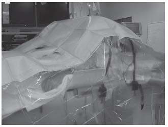
Figure 6.6 • Positioning of patient during antegrade common femoral artery access with head toward foot of table and feet toward the head of the table.
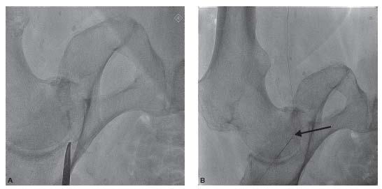
Figure 6.7 • Antegrade common femoral artery access. A: Fluoroscopic image demonstrating location of head of femur. B: Fluoroscopic image demonstrating the location of the arterial puncture at the level of the middle of the head of the femur (arrow). C: Picture from the same patient demonstrating the location of the skin puncture by the micropuncture needle to achieve the arterial puncture shown in B.
Antegrade CFA access requires careful attention to detail, particularly in obese patients, where the bleeding risk is significantly increased (9). In our laboratory, the patient is draped as shown in Figure 6.6. With this arrangement, the patient’s head is placed toward the foot of the table, and the patient’s feet are at the head of the table. Criss-crossing flexible bars are arranged as shown to provide a “tent” effect over the patient’s face and upper trunk with the goal of improving patient comfort. This arrangement has many advantages for the operator, including optimization of the length available toward the foot of the table for interventional equipment.
In order to puncture the CFA above the bifurcation, the skin puncture site of the needle is often much higher than would be anticipated by the inexperienced operator. Our practice is to use a micropuncture access set (with a 7-cm-long 21-G needle) and to perform the puncture under direct fluoroscopic guidance (Fig. 6.7). The 0.018″ wire is then advanced into the superficial femoral artery (SFA) through the micropuncture needle. One must ensure that the 0.018″ wire is in the SFA before advancing the sheath. If there is prominent calcification in the SFA, this is straightforward. In patients with no calcium in the SFA, a useful rule of thumb is to visualize the wire coursing along the usual course of the SFA (i.e., initially medially and then laterally as it crosses the border of the femur in the typical location of Hunter’s canal). The coaxial sheath is then introduced and the 0.018″ wire is exchanged for a 0.035″ wire, which is used to allow delivery of the arterial access sheath. We would strongly recommend using a stiff-bodied 0.035″ wire for the latter maneuver (e.g., SupraCore, SuperStiff Amplatz wire), as failure to deliver the sheath over the 0.035″ will require a repeat attempt at vascular access.
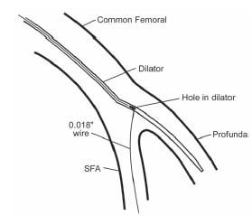
Figure 6.8 • Use of Cope–Saddekni superficial femoral artery access dilator to wire the SFA during an antegrade access of the common femoral artery.
Body habitus strongly influences the difficulty of antegrade access. In thin individuals, access is usually straightforward. However, in obese individuals, the skin puncture site will be significantly higher than normal, and the angle at which the needle enters the CFA is significantly steeper. In some very obese patients, the 7-cm needle may not be long enough, and a 12-cm needle may be required. The steep angle of entry of the needle with the CFA in the anterior–posterior (AP) plane often makes subsequent delivery of the coaxial catheter and/or vascular access sheath (see above) very difficult. In this regard, it is very important during attempts at antegrade access that the needle be aligned with the vessel in the medial–lateral (ML) plane, as excessive angulation in both the AP and ML planes will sometimes make delivery of the sheath impossible. In patients with severe calcification of the CFA, a stiffened micropuncture coaxial sheath is often required to achieve entry to the artery and should always be available during antegrade access cases. Occasionally, the micropuncture coaxial sheath cannot be delivered over the 0.018″ wire, usually due to severe calcification that is compounded by angulation issues. In such cases, direct antegrade puncture using a conventional 18-G Cook needle, followed by introduction of a SuperStiff Amplatz wire (with 1 cm soft tip) will typically allow successful antegrade access.
The other major challenge that is sometimes encountered during antegrade access is persistent tracking of the 0.018″ guidewire into the profunda femoral branch with failure to wire the SFA. In this circumstance, special dilators (e.g., Cope-Saddekni dilator; Fig. 6.8) may help access to the SFA. Another option is to proceed with placement of the micropuncture coaxial sheath and vascular access sheath into the profunda femoral artery. After advancing a stiff-bodied 0.014″ wire (e.g., GrandSlam) into the profunda, the access sheath is withdrawn to the level of the CFA bifurcation (using small injection of contrast). A steerable 0.035″ wire (e.g., angled glidewire) supported by an angulated catheter (angled glide catheter, Bernstein) can then be used to facilitate wiring of the SFA, and subsequent delivery of the sheath.
Upper Extremity Access—Brachial and Radial
Access from the upper extremity arteries offers the advantage of early ambulation and a reduced risk of bleeding complications. The downside of these access sites is the limited sheath sizes that can be used (5 to 6 Fr. at radial, 6 to 7 Fr. at brachial), particularly in smaller female patients, and the increased risk of ischemic complications (10). Even more serious is the risk of embolization to the cerebral circulation that may occur because of instrumentation of the aortic arch or passage of equipment across the origin of the vertebral or right common carotid arteries.
Brachial artery puncture is performed with the arm and forearm extended and slightly abducted. The site of puncture should be in the area of maximal arterial pulsation but care should be taken not to stick the brachial artery significantly above the antecubital crease as it increases the risk of bleeding (Fig. 6.9). A 4-cm-long 21-G micropuncture needle is optimal for most patients. Particular attention should be paid to hemostasis following removal of brachial artery sheaths, since the location of the arteriotomy away from an easily compressible bony structure can make hemostasis difficult. significant hematomas that cause severe patient discomfort and pseudoaneurysm formation occur following brachial access and can be minimized by applying pressure for at least 20 to 30 minutes following sheath removal.
Radial artery puncture is performed with the wrist extended (i.e., dorsiflexed) and the forearm and hand supinated. The site of puncture is generally ~1 to 2 cm proximal to the wrist crease. We use a 2.5-cm or 4-cm-long micropuncture 21-G needle for all radial artery punctures. Other operators use a peripheral IV access system (e.g., Angiocath™) to puncture the radial artery (evidenced by the back flash of blood) and advance through the posterior wall of the radial artery. The needle is then withdrawn, and the sheath is slowly withdrawn until pulsatile flow is visualized. The guidewire is then advanced into the radial artery and the radial artery sheath is placed.
Both the radial and the brachial arteries are prone to significant spasm and thrombosis in response to instrumentation. Aggressive administration of vasodilators (e.g., nitroglycerin, verapamil) and heparin (at least 3000 units) directly into the sheath is mandatory following sheath insertion to minimize these risks. During brachial artery access, operators must be aware of the potential for anomalous origin of the radial or the ulnar arteries from the axillary or high brachial artery (Fig. 6.10). In addition, the potential for wires and catheters to track along the course of the recurrent radial branch when using radial artery access should be appreciated as this can result in trauma to this branch and hematoma formation (Fig. 6.11).

Stay updated, free articles. Join our Telegram channel

Full access? Get Clinical Tree


