5 Advanced Cardiopulmonary Monitoring
Note 1: This book is written to cover every item listed as testable on the Entry Level Examination (ELE), Written Registry Examination (WRE), and Clinical Simulation Examination (CSE).
The listed code for each item is taken from the National Board for Respiratory Care’s (NBRC) Summary Content Outline for CRT (Certified Respiratory Therapist) and Written RRT (Registered Respiratory Therapist) Examinations (see http://evolve.elsevier.com/Sills/resptherapist/). For example, if an item is testable on both the ELE and the WRE, it will simply be shown as: (Code: …). If an item is only testable on the ELE, it will be shown as: (ELE code: …). If an item is only testable on the WRE, it will be shown as: (WRE code: …).
MODULE A
1. Capnography (exhaled CO2 monitoring)
b. Recommend capnography to obtain additional data (Code: IC10) [Difficulty: ELE: R, Ap; WRE: An]
There are three main reasons to recommend capnography. The first reason is to assess a patient’s ventilation. General anesthesia and even conscious sedation can result in a blunting of the patient’s normal drive to breathe. Several clinical or pathologic situations (discussed later in this chapter) can result in an abnormal increase or decrease in the carbon dioxide level. Second, capnography helps evaluate the effectiveness of cardiopulmonary resuscitation efforts. See the discussion in Chapter 11. Third, capnography can be used to help identify the proper placement of an endotracheal tube. If the tube is within the patient’s trachea or a main stem bronchus, the exhaled tidal volume will contain carbon dioxide. See the discussion in Chapter 12.
c. Perform the bedside procedure (Code: IB9c and IIIE3d) [Difficulty: ELE: R; WRE: Ap, An]
The capnometer is calibrated by comparing a gas sample without carbon dioxide (possibly room air) with a second gas sample containing a known amount of carbon dioxide. The first gas sample without CO2 should give a “zero” reading. Adjust the calibration control to zero if needed. The second sample usually contains 5% to 10% carbon dioxide. The capnometer should display a CO2 level that matches the amount in the known gas sample. Adjust the calibration control as necessary. The carbon dioxide level can be documented as a percent or fraction (FACO2) or as a partial pressure (PACO2).
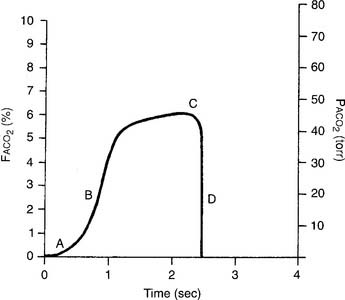
The capnograph is a strip chart recorder that provides a copy of the patient’s exhaled carbon dioxide curve. There are at least two paper speeds that are useful for different purposes. The fast speed is most useful for evaluating sudden changes in the patient’s condition. Each individual breath is easily seen (Figure 5-1). The slow speed is most useful for trend monitoring (Figure 5-2).
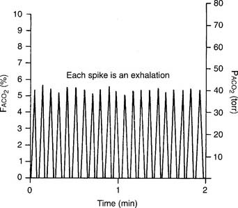
Figure 5-2 Normal capnograph tracing taken at a slow speed. The percentage of exhaled alveolar CO2 is shown on the left vertical scale as FACO2. The partial pressure of exhaled alveolar CO2 is shown on the right vertical scale as PACO2. The slow speed results in a blending of parts A, B, and C of the fast-speed tracing (Figure 5-1). Each spike is part C of the curve and marks an exhalation. A slow-speed tracing is more useful in trend monitoring of a patient than a fast-speed tracing.
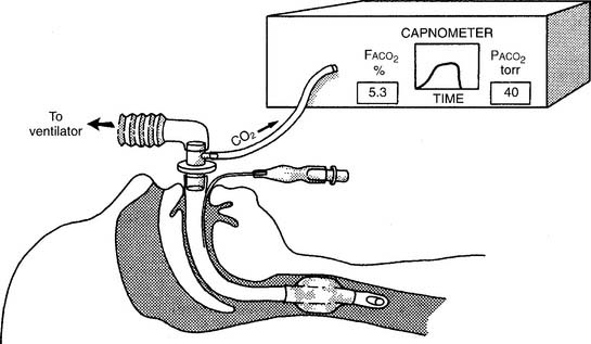
Two different gas sampling methods exist: mainstream and sidestream. The mainstream method involves having the infrared sensing unit at the airway; usually it is attached directly to the endotracheal/tracheostomy tube. If the patient is on a ventilator, the sampling adapter must be placed between the endotracheal tube and the ventilator circuit (with or without mechanical dead space). All inspired and expired gas passes through the sensor (Figure 5-3).
The sidestream method employs a capillary tube placed so that a small sampling of the patient’s exhaled gas can be drawn into the capnometer for analysis. It is not necessary for the patient’s entire breath to pass through the sampling adapter; therefore it can be used in an unintubated patient by taping the sampling catheter a short distance into a nostril. If the patient is on a ventilator, the sampling adapter must be placed between the endotracheal tube and the ventilator circuit (with or without mechanical dead space). Remember that the patient’s exhaled tidal volume (VT) and minute volume ( E) are reduced by the amount that is drawn into the capnometer (Figure 5-4).
d. Interpret the results from the procedure (Code: IB10c, IIIE4e) [Difficulty: ELE: R, Ap; WRE: An]
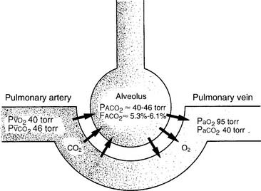
It is known that carbon dioxide diffuses from the higher concentration in the tissues to the venous blood and to the lungs to be exhaled. Figure 5-5 shows the normal physiology behind capnography. This diffusion or “flow” of CO2 results in a measurable gradient or difference. In a healthy, upright sitting person, a close relationship exists between carbon dioxide levels in both venous blood and arterial blood and the amount of exhaled carbon dioxide gas. The carbon dioxide level at the end of exhalation is most frequently monitored during patient care. This is called the end-tidal carbon dioxide pressure (PetCO2). When ventilation and perfusion match well, as in a healthy upright person, the gradient between the arterial carbon dioxide level (PaCO2) and the PetCO2 is between 2 and 3 torr, with a range of 1 to 5 torr. The gradient will show the PetCO2 level to be less than the PaCO2 level. This is because the PetCO2 value is an average of exhaled carbon dioxide levels from all lung areas.
Box 5-1 lists normal values of capnography. Three factors influence capnography’s use and the interpretation of the results. (1) The first factor is the patient’s metabolism. The average resting adult produces about 200 mL of CO2 per minute, and fever and exercise increase this value. Hypothermia, sleep, and sedation decrease CO2 production. Exhaled CO2 is monitored during a cardiopulmonary resuscitation (CPR) attempt to determine the effectiveness of circulation and ventilation attempts and to decide if the efforts should be continued or stopped. If no carbon dioxide is being exhaled despite proper CPR procedures, the physician may conclude that the patient’s metabolism has stopped altogether and death has occurred. There would then be nothing to gain by continuing cardiopulmonary resuscitation (CPR) efforts.
BOX 5-1 Normal Blood Gas and Capnography Values (Based on a Sea Level Barometric Pressure of 760 torr)*
PaCO2† is 40 torr (range of 35 to 45 torr).
The pressure of exhaled alveolar CO2 (PACO2) ranges from 35 to 43 torr with the breathing cycle.
The percentage of end-tidal CO2 (FACO2) is about 4%-6% and trends with the PaCO2 level.
(2) Although not a major factor, the patient’s cardiac output is another factor that influences the use of capnography. Sepsis, which might double a patient’s cardiac output, reduces the PCO2 level only a few torr (millimeters of mercury [mm Hg]). Cardiogenic shock, which reduces the cardiac output, raises the partial pressure of CO2 (PCO2) only a few torr.
(3) The third and most important factor is alveolar ventilation. A doubling of alveolar ventilation, under steady-state conditions for carbon dioxide production, results in a halving of the PCO2 levels in arterial blood and alveolar gas. However, a reduction of alveolar ventilation to half of its previous level will result in the PaCO2 and PACO2 levels being doubled (Figure 5-6).
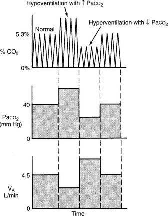
Figure 5-6 Relationship between alveolar ventilation, PaCO2, and exhaled percent CO2.
(From Pilbeam SP: Mechanical ventilation: physiological and clinical applications, ed 4, St Louis, 2006, Mosby.)
2. Arterial–end-tidal carbon dioxide gradient
a. Perform the bedside procedure (Code: IB9c and IIIE3d) [Difficulty: ELE: R; WRE: Ap, An]
b. Interpret the results from the procedure (Code: IB10c, IIIE4e) [Difficulty: ELE: R, Ap; WRE: An]
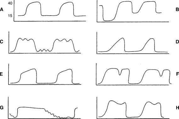
Review the components of a fast-speed capnography tracing in Figure 5-1 to understand a normal person’s expiratory pattern. Figure 5-7 shows eight different abnormal fast-speed capnography tracings. See the figure legend for an explanation of each problem. As the patient returns to normal, the tracing should approach that shown in Figure 5-1.
3. Arterial–residual volume alveolar carbon dioxide gradient
a. Perform the bedside procedure (Code: IB9c and IIIE3d) [Difficulty: ELE: R; WRE: Ap, An]
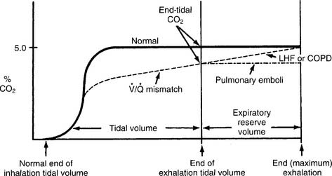
Have a cooperative patient exhale maximally to residual volume (RV) through the capnography unit. The graphic results will be similar to that shown in Figure 5-8. The usual P(a-RV)CO2 gradient in a healthy person is about 3 to 5 torr, and should be less than 7 torr. The wider the gradient, the greater is the ventilation to perfusion ( /
/ ) mismatching. A gradient of more than 13 torr is considered to be markedly abnormal. This may be the case in patients with chronic obstructive pulmonary disease (COPD), pulmonary emboli, left heart failure (LHF), or hypotension.
b. Interpret the results from the procedure (Code: IB10c, IIIE4e) [Difficulty: ELE: R, Ap; WRE: An]
When comparing the normal (solid line) tracing in Figure 5-8 with the  /
/ mismatching (dashed line) tracing, note the increased gradient at end-tidal CO2. With continued exhalation to residual volume, the left heart failure and COPD patients have a narrowing of the gradient. This can be used clinically to follow these patients’ progress and response to treatment. The patient with a large pulmonary embolism will not have such a narrowing of the gradient as he or she exhales to residual volume. This patient’s gradient will narrow to normal as the embolism is resolved and the physiologic dead space returns to normal.
Past exams have often had one question that requires the interpretation of capnography results, especially the end-tidal CO2 value (PetCO2). Examples include a change in alveolar ventilation, shallow breathing, and CPR attempt.
MODULE B
1. Review dead space to tidal volume data in the patient’s chart (Code: IA7e) [Difficulty: ELE: R; WRE: Ap]
2. Perform the bedside procedure (ELE Code: IB9l) [Difficulty: ELE: R, An]
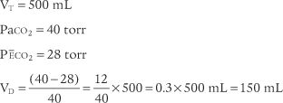
The procedure is the mathematical comparison of a person’s dead space volume with tidal volume. Steps in the traditional procedure follow (Figure 5-9):
a. Determine the decimal fraction or percentage of dead space
Place both carbon dioxide values into this formula, which is derived from the original Bohr formula:
VD/VT or VD the patient’s physiologic dead space
PaCO2 = the patient’s arterial carbon dioxide pressure
PĒCO2 = the patient’s average exhaled carbon dioxide pressure
The following example is based on an abnormal adult:
b. Determine the dead space volume
Place both carbon dioxide values into this formula, which is derived from the original Bohr formula:
VD VT or VD the patient’s physiologic dead space
VT = the average exhaled tidal volume
PaCO2 = the patient’s arterial carbon dioxide pressure
PĒCO2 = the patient’s average exhaled carbon dioxide pressure
The following example is based on a normal adult:
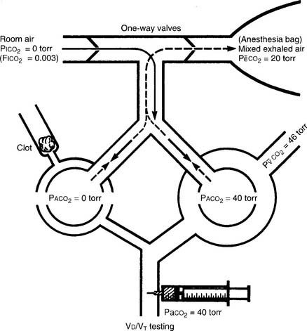
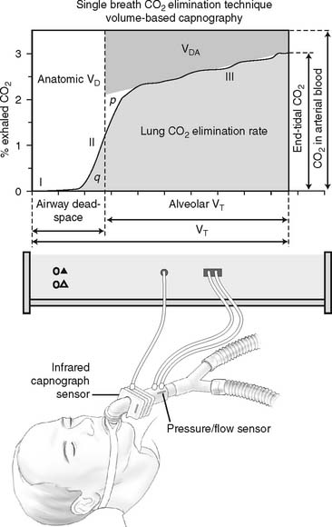
The recent advent of volumetric capnography technology allows the patient’s dead space to be rapidly determined. These units can simultaneously measure the patient’s exhaled tidal volume and the variable percentage of carbon dioxide found during the exhalation (Figure 5-10). The computer that is integrated with the volumetric capnography unit then calculates the volume of dead space as a fraction of the exhaled tidal volume. Figure 5-11 shows how volumetric capnography can be set up to measure the dead space of a patient requiring mechanical ventilation. This technology permits the rapid assessment of a patient as treatment is being performed. For example, if a patient had a large pulmonary embolism resulting in significant dead space, a clot-dissolving medication such as streptokinase (Kabikinase or Streptase) or alteplase (Activase) would be given. These “clot buster” medications will rapidly dissolve the patient’s pulmonary embolism. With volumetric capnography, the dead space volume can be monitored as it normalizes when blood flow through the lungs is restored.
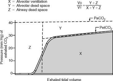
Figure 5-10 A graphic representation of the factors involved in the calculation of a patient’s dead space volume, or dead space to tidal volume (VD/VT) ratio, through volumetric capnography. These units can measure exhaled carbon dioxide (by pressure or percentage) at time intervals as the patient’s tidal volume is exhaled. Review Figure 5-1, as needed, for a normal capnograph tracing.
3. Interpret the results of the VD/VT calculation (Code: IB10l) [Difficulty: ELE: R, Ap; WRE: An]
Physiologic dead space is composed of the following:
The following conditions or pulmonary disorders can cause the ratio to vary from the normal range:
a. Decreased VD/VT ratio
c. Increased dead space effect with ventilation greater than perfusion ( >
>  )
)
MODULE C
1. Blood pressure
b. Recommend blood pressure measurement to obtain additional data (Code: IC11) [Difficulty: ELE: R, Ap; WRE: An]
c. Perform blood pressure measurement (Code: IB9m, IIIE3e) [Difficulty: ELE: R, Ap; WRE: An]
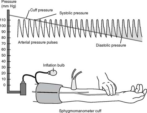
The general steps in measuring blood pressure were described in Chapter 1. The BP is usually measured on either of the patient’s arms. Necessary equipment includes the proper size of blood pressure cuff, a sphygmomanometer to measure the pressure, and a stethoscope to hear the sounds of bloodflow returning through the brachial artery. Figure 5-12 shows the basic elements of the procedure. The cuff is inflated to a pressure that is greater than the patient’s systolic pressure. As the pressure in the cuff is gradually decreased, the first sound heard (Korotkoff sounds) is the systolic pressure. The pressure reading at which this sound ceases is the diastolic pressure. Blood pressure measurement can usually be performed manually by a respiratory therapist or other trained health care professional. If BP measurement is needed on a frequent basis, an automated blood pressure measurement system can be set up on the patient’s arm. This unit can be programmed to measure the BP on a schedule and can also have high and low blood pressure alarm limits established as a safety feature.
e. Interpret the results of the blood pressure measurement (Code: IB10m, IIIE4c) [Difficulty: ELE: R, Ap; WRE: An]
Review the general discussion on blood pressure in Chapter 1. The following are normal blood pressure values:
Patients who have values that are higher or lower than these should be further evaluated. Know the following values since they represent a serious patient problem:
2. Central venous pressure (CVP) monitoring
a. Review central venous pressure measurement data in the patient’s chart (Code: IA8b) [Difficulty: ELE: R; WRE: Ap]
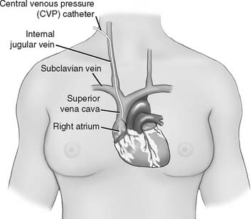
The central venous pressure (CVP) is the pressure measured in a patient’s superior vena cava, just above the right atrium. See Figure 5-13. Review previous patient data to understand whether there is an abnormality. Compare the current data with the earlier information to determine if there has been a change in the patient’s condition. See Box 5-2 for normal values.
b. Recommend the insertion of a central venous pressure catheter to obtain additional data (WRE code: IC12) [WRE Difficulty: R, Ap, An]
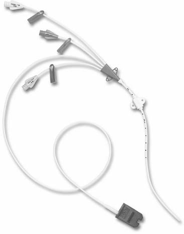
A single-lumen central venous pressure catheter (also called a CVP line) is inserted into many patients for one or more reasons: (1) to monitor the patient’s right-sided (right atrium) heart pressure, (2) to rapidly administer a large volume of intravenous fluids, and (3) to administer cardiac medications during a CPR attempt (preferred route). Recently, the development of a triple-lumen CVP catheter with integrated fiberoptic channel (Edwards Lifesciences, LLC) has enabled the continuous monitoring of central venous oxygen saturation (ScvO2), in addition to the previously mentioned uses. See Figure 5-14.
c. Recommend central venous pressure measurement to obtain additional data (Code: IC11) [Difficulty: ELE: R, Ap; WRE: An]
d. Perform central venous pressure measurement (Code: IB9e) [Difficulty: R, Ap, An]
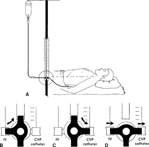
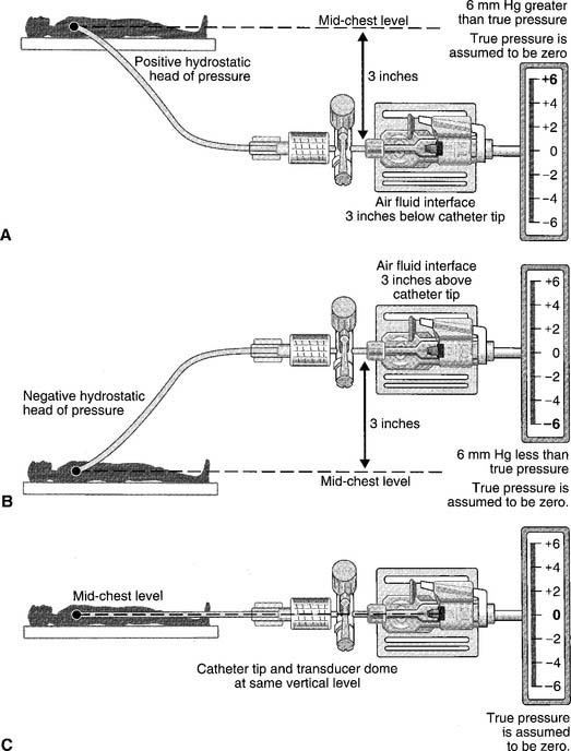
The catheter is usually inserted into the right jugular vein or right subclavian vein and advanced to just above the superior vena cava. When set up for monitoring pressure, it measures the right atrial pressure (see Figure 5-15 for how to perform the procedure). Note that the stopcock must be kept at the midchest (midheart) level. Usually a mark is placed at this location (on the patient’s chest) for consistency. Raising the stopcock above the mark results in an incorrectly low reading. Lowering the stopcock below the mark results in an incorrectly high reading. See Figure 5-16. Clinical practice is very important in learning how to perform this procedure. It is important that the patient breathes spontaneously if at all possible. Peak pressures during inspiration on a mechanical ventilator may artificially raise the CVP reading. Positive end-expiratory pressure (PEEP) may also raise the CVP reading. If the patient cannot be removed from the ventilator, take the reading during exhalation. Make a note of the settings and that the reading was taken with the patient on the ventilator. Record the data in the patient’s chart or flow sheet.
Past exams have asked about the proper placement of the CVP stopcock or arterial pressure transducer at the midchest (midheart) location to ensure accurate pressure measurements. Usually a mark is placed on the patient’s chest for a consistent measurement point. Review Figure 5-16 for the effects of misplacement.
Past exams have asked about the proper placement of the CVP stopcock or arterial pressure transducer at the midchest (midheart) location to ensure accurate pressure measurements. Usually a mark is placed on the patient’s chest for a consistent measurement point. Review Figure 5-16 for the effects of misplacement.
e. Interpret the results of the central venous pressure measurement (Code: IB10m, IIIE4c) [Difficulty: ELE: R, Ap; WRE: An]
As noted earlier, the CVP is a measure of the pressure in the right atrium. The two main factors that influence the right atrial pressure are the blood volume returning to it and the functioning of the right ventricle (see Box 5-2 for normal CVP readings).
Memorize the values listed in Box 5-2. Expect to see several questions in which these values are used as patient data or as options to answer a question. The normal values must be understood to identify abnormal values and know why they are abnormal.
Memorize the values listed in Box 5-2. Expect to see several questions in which these values are used as patient data or as options to answer a question. The normal values must be understood to identify abnormal values and know why they are abnormal.
3. Pulmonary artery pressure monitoring
a. Review pulmonary artery pressure data in the patient’s chart (Code: IA8b) [Difficulty: ELE: R; WRE: Ap]
The pulmonary artery pressure (PAP) is the systolic and diastolic pressure found in either pulmonary artery. It can be measured only through a pulmonary artery catheter. (The NBRC often refers to this as a flow-directed pulmonary artery catheter.) Review the patient’s previous values before taking another pressure reading to make a comparison. Box 5-2 shows normal cardiopulmonary values.
b. Recommend the insertion of a pulmonary artery catheter for additional data (WRE code: IC12) [WRE Difficulty: R, Ap, An]
To read the PAP, a pulmonary artery catheter (PAC) must be inserted through a vein and passed through the right atrium and right ventricle into the pulmonary artery. The common insertion sites, in descending order of preference, are the basilic vein in either the right or the left arm, the right internal jugular or subclavian vein, or the right or left femoral vein. The pulmonary artery catheter is also commonly called a Swan-Ganz catheter after the inventors who gave their names to a particular brand. The catheters are available in different lengths and diameters for pediatric and adult patients. See Figure 5-17 for a typical adult catheter.
c. Recommend pulmonary artery pressure measurement to obtain additional data (Code: IC11) [Difficulty: ELE: R, Ap; WRE: An]
d. Perform pulmonary artery pressure measurement (Code: IB9m, IIIE3e) [Difficulty: ELE: R, Ap; WRE: An]
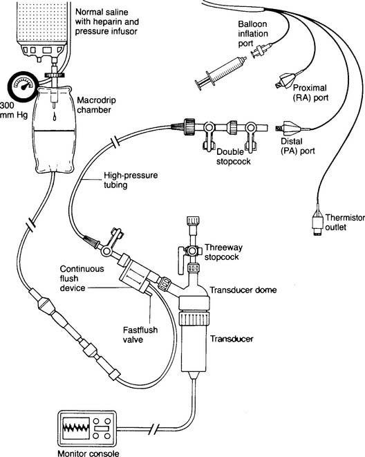
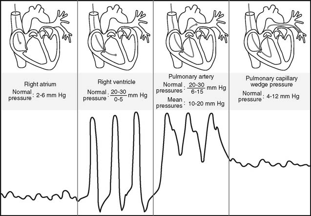
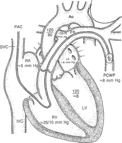
Figure 5-17 is an illustration of a 7-French quadruple-lumen thermodilution pulmonary artery catheter. Besides measurement of PAP, it is capable of being used to measure cardiac output. Figure 5-18 illustrates how a pulmonary artery catheter could be arranged with a pressure transducer and pressure monitor. Figure 5-19 shows a representation of the series of pressure waveforms seen as the catheter is advanced through the heart and into the wedged position in a branch of the pulmonary artery. Figure 5-20 shows a larger cutaway view of the heart with a PAC and normal heart chambers and related pressures.
e. Interpret the results of pulmonary artery pressure measurement (Code: IB10m, IIIE4c) [Difficulty: ELE: R, Ap; WRE: An]
Again, the PAP is the systolic and diastolic pressure found in the pulmonary artery (see Box 5-2 for normal values). Elevated PAP values are usually seen with the following conditions:
Stay updated, free articles. Join our Telegram channel

Full access? Get Clinical Tree



 O2). However, in questions referring to capnography, the NBRC has used both mm Hg and torr in its questions that relate to exhaled CO2 (such as PACO2 and PETCO2).
 O2). However, in questions regarding capnography, the NBRC has used both mm Hg and torr in its questions that relate to exhaled CO2 (such as PACO2 and PetCO2).




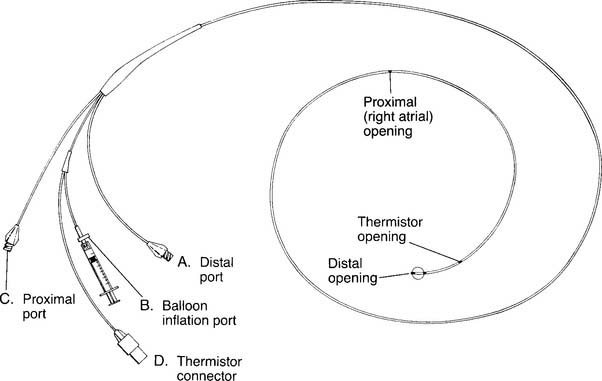
 O2 determination. B, Balloon inflation port is used to inflate the balloon for inserting the catheter and for obtaining a PCWP reading. C, Proximal port is used for measuring central venous pressure and for injecting iced saline for a thermodilution cardiac output study. The iced saline exits from the right atrial opening. D, Thermistor connector attaches to the cardiac output computer. A bimetallic wire runs through the catheter to the thermistor opening, where it is exposed to temperature changes of the blood and cold injectate. (NOTE: Not all catheters are capable of measuring cardiac output. Some catheters have other special features such as continuously measuring venous saturation or cardiac pacemaker leads.)