Fig. 7.1
Interventional MRI and angiographic fusion. Interventional applications of MRI allow real-time fusion of angiographic and MRI images in hybrid MRI/angiosuites for direct procedural guidance (Image courtesy of Dr. Lederman; adapted with permission from Ratnayaka K et al. (2009) JACC Cardiovasc Interv 2:224–230)
7.2.1 Imaging and Transcatheter Aortic Valve Implantation
7.2.1.1 Anatomy
Aortic root anatomy, including the aortic valve and coronary artery ostia, is complex [77–79]. The geometry and relationship of the aortic root structures change throughout the cardiac cycle [80–83]. Implantation of a stent/valve has incompletely understood the consequences of these structures and their relationships.
The aortic annulus describes the interface between the left ventricular outflow tract and the aortic root at the commissures of the aortic valve leaflets (Fig. 7.2). The three commissures extend upward into the aortic root similar to the shape of a crown or the struts of a bioprosthetic valve. The “annular” level at the lowest point of the valve hinge point (“inferior virtual basal ring”) defines the level where valve prostheses are sutured or secured. During valve surgery the annulus is fitted to the valve. On the other hand, when the transcatheter valve is deployed, the stent/valve must adjust to the “aortic root.” Therefore, in addition to size and shape, the composition and material properties of the surrounding structures have important implications for the interaction between device and root. Approximately 2/3 are in contact with ventricular myocardium, and the remaining 1/3 are composed of the aortic leaflet of the mitral valve [31].
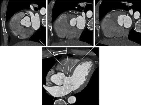

Fig. 7.2
Relationship between aortic valve, left ventricular outflow tract (LVOT), and anterior mitral leaflet. The upper panels show (left to right) cross sections through aortic valve, LVOT, and anterior mitral leaflet. The close relationship between these structures is demonstrated
The three individual cusps of the aortic valve are attached to the aortic wall along the commissures in a crescentic fashion (Fig. 7.3). Behind the cusps are the outward bulging sinuses of Valsalva, with the origins of the coronary arteries at the superior aspect of the left and right aortic sinuses. There is a wide variation in distance between the leaflet tips and the coronary ostia, and in about 50% of patients, the length of the left coronary leaflet exceeds the distance between the annulus and the ostium of the left coronary artery.
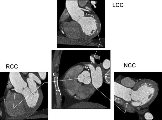

Fig. 7.3
Relationship between aortic valve cusps and coronary ostia. The central panels show a cross section through the aortic root with the three aortic valve cusps. The three surrounding panels show oblique sagittal images of each cusp. LCC left coronary cusp; RCC right coronary cusp; NCC noncoronary cusp
The sinotubular junction describes the margin between the aortic root and tubular ascending aorta and has an important role in maintaining valve competence (Fig. 7.4) [84]. During the TAVI procedures, the sinotubular junction provides support for the deployment balloon; depending on valve design (short vs. long), the sinotubular junction and proximal ascending aorta are important for proper implantation (distal anchor zone). Please see Chap. 2 for more information on the anatomy of the semilunar valves.
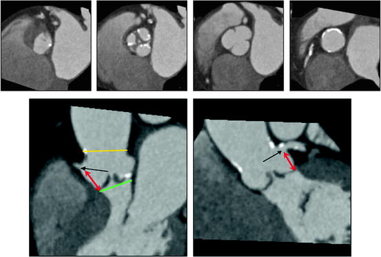

Fig. 7.4
Aortic root, aortic valve, and coronary ostia. The upper panels show (left to right) cross sections at the “aortic annulus,” aortic valve, sinuses of Valsalva, and sinotubular junction. There is moderate thickening and calcification of the aortic valve leaflets
7.2.1.2 Imaging
The position of the aortic root relative to the body axis and corresponding alignment of the X-ray plane are critically important for precise placement of the stent/valve. With angiography, overlap-free visualization of the three coronary cusps, which are oriented along the aortic valve plane, typically requires caudal angulation in the RAO projection and cranial angulation in the LAO projection. The current standard approach is based on the identification of X-ray root angiograms in one or preferably two orthogonal planes prior to the procedure after repeated root injections. Recent CT data demonstrates that a pre-procedural multi-detector CT angiography of the aortic root allows prediction of the optimal angulation of the root angiogram, which could facilitate the angiographic procedure and reduce the number of root injections (Fig. 7.5) [85, 86].
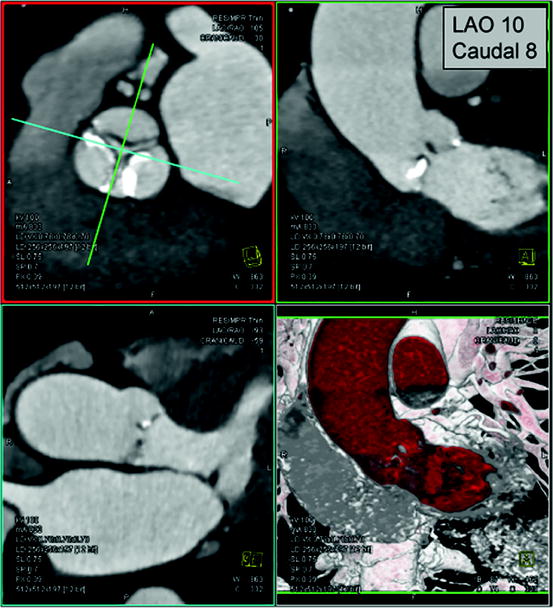

Fig. 7.5
Prediction of angiographic planes for transcatheter aortic valve implantation. In a double-oblique reconstructed image, the crosshair of the cut-planes is centered on the aortic valve (left upper panel) and rotated to obtain images of the aortic root, described in angiographic coordinates/planes (right upper panel)
As described above, using imaging modalities, the annulus plane is defined as the plane created by the lowest hinge point of the three leaflets of the aortic valve (“inferior virtual basal ring”) (Figs. 7.2 and 7.4). Detailed 3D analysis demonstrates that this clinically defined annulus is typically elliptical [87–97], and therefore, maximal and minimal annular diameters are reported with CT. Mean annular diameter by CT correlates best but is typically slightly larger than that obtained with TEE. Measurement of the distance between the coronary arteries, artery ostia, and distal tip of the aortic valve leaflets is important and can be derived from angiography, CT, and TEE (Fig. 7.4). In the case of a low ostium or a long leaflet, there is increased risk of coronary (particular left main) occlusion [87, 89, 90, 94].
Imaging allows detailed description of the presence and distribution of valve and root calcification (Fig. 7.6) [98–104]. For example, calcification frequently extends from the aortic valve commissures to the base of the anterior mitral leaflets and sinotubular junction. The amount and distribution of calcification in the proximal device landing zone at the annulus affect sealing of the prosthesis. Aortic calcification of the sinotubular junction can influence precise placement of the valve during TAVI by restricting balloon expansion and potentially leading to the ventricular displacement of device at the time of deployment.
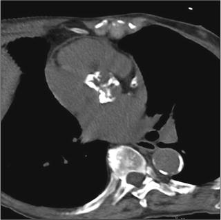

Fig. 7.6
Dense calcification of aortic valve. In this image of a noncontrast-enhanced scan, dense calcification is seen along all three aortic valve cusps. This pattern suggests a tricuspid valve. Using calcium scoring software, the extent of calcification can be quantified
Direct observation of the aortic valve opening area allows for correlation of the pattern of valve opening with leaflet anatomy and leaflet calcification. Direct planimetry of the aortic valve opening area with CT has been shown to provide reproducible results in comparison to TEE and MRI (Fig. 7.7) [105–112].
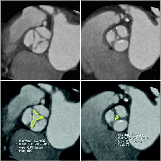

Fig. 7.7
Image reconstruction in systolic and diastolic phase of the cardiac cycle. Image reconstruction in systolic (left) and diastolic (right) phase of the cardiac cycle demonstrates restricted systolic opening and incomplete diastolic coaptation, consistent with moderate aortic stenosis and mild insufficiency, respectively
During periprocedural 3D TEE, the biplane imaging mode is valuable in simultaneously imaging the aortic valve in both the short- and long-axis views, both in 2D and in color Doppler (Fig. 7.8). This allows the accurate positioning of the prosthetic device in the center of the stenotic valve in both orientations, as well as rapidly localizing postimplantation paravalvular regurgitation.
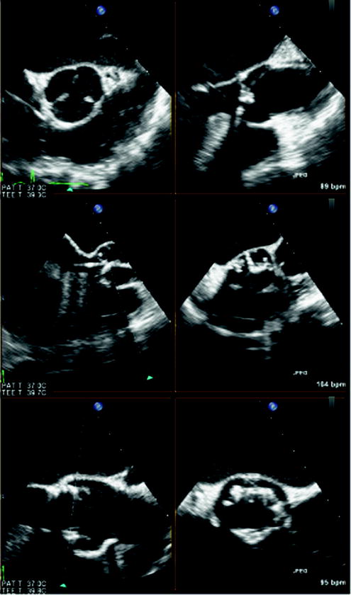

Fig. 7.8
Biplane real-time three-dimensional (3D) echocardiography. Biplane real-time imaging of a patient with severe aortic stenosis undergoing transcatheter aortic valve implantation (TAVI), in both short and long axis, before (top panel), during (middle panel), and after (bottom panel) device deployment. Simultaneous imaging of the aortic valve in two planes in high spatial and temporal resolution is crucial for the precise positioning of the prosthetic device in TAVI
7.2.2 Transcatheter Mitral Valve Procedures
7.2.2.1 Anatomy
The annulus of the mitral valve is an oval, saddle-shaped structure which is formed by continuity of the left atrial tissue with the left ventricular tissue, as well as the base of the mitral valve leaflets (Figs. 7.9 and 7.10) [113, 114]. The mitral valve apparatus consists of the annulus, leaflet, chordae, and the papillary muscles. The annulus is divided into anterior and posterior parts by the commissures. The anterior leaflet is larger in length but covers only about 1/3 of the circumference of the annulus. The posterior leaflet is shorter in length but covers approximately 2/3 of the annulus. The chordae arise from the papillary muscle tips and then span to the leaflets in a fan-shaped manner (Fig. 7.11). There are two main chordae arising from each head of the papillary muscle, reaching each of the leaflets. However, there is a considerable variation in the origin and distribution of the chordae.
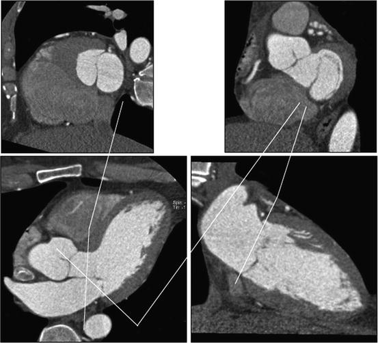
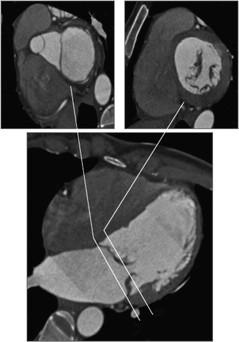
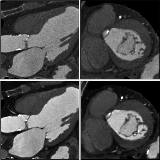

Fig. 7.9
Relationship between LVOT, anterior mitral leaflet, and mitral annulus. The upper panels show (left to right) cross sections of the LVOT/anterior mitral leaflet and mitral annulus. The close relationship of the structures is demonstrated

Fig. 7.10
Mitral annulus and mitral valve leaflets. The upper panels show a cross section through the mitral annulus (left) and mitral leaflets close to the tips

Fig. 7.11
Mitral leaflets, mild mitral annular calcification, and papillary muscles. In this image, mild mitral annular calcification is seen in the infero-lateral aspect of the annulus. The images also show the posterior papillary muscles and chordae tendineae. The images are reconstructed with standard “filtered back projection” (upper panels) and “iterative reconstruction” (lower panels). Iterative reconstruction is associated with significantly decreased image noise
The coronary sinus (CS) extends along the left atrioventricular groove close to the mitral annulus and drains into the right atrium. In the context of sinus annuloplasty procedures, a major concern is the close proximity of the CS to the left circumflex artery (LCX) andthe potential risk of CS-based devices potentially impinging on the LCX [115]. See Chap. 1 for more information on the anatomy of the atrioventricular valves.
7.2.2.2 Imaging
Three-dimensional imaging allows a detailed understanding of the mitral valve apparatus including the mitral annulus and leaflets and has been extensively described with echocardiography [116–121]. Description of mitral valvular anatomy is critical for procedures involving the mitral leaflets, including mitral valve clip procedures and percutaneous closure of paravalvular regurgitation. Real-time 3D and full-volume acquisition with TEE allows imaging of the entire mitral valve and annulus over full cardiac cycles [47, 122–125]. Therefore, 3D echocardiography is a critical part of the pre-procedural assessment of patients with mitral regurgitation and allows clarification of etiology and assessment of amenability of the mitral valve to percutaneous procedures (Fig. 7.12). For periprocedural guidance, full-volume 3D echocardiography data acquisition is less useful because of the need for offline analysis. However, real-time 3D echocardiography with its enface mitral valve view from the left atrium similar to the surgeon’s view, as well as simultaneous biplane imaging with its high temporal and spatial resolutions both in 2D and color Doppler modes, is invaluable for procedures such as mitral valve clip (Fig. 7.13) and percutaneous closure of paravalvular regurgitation (Fig. 7.14).
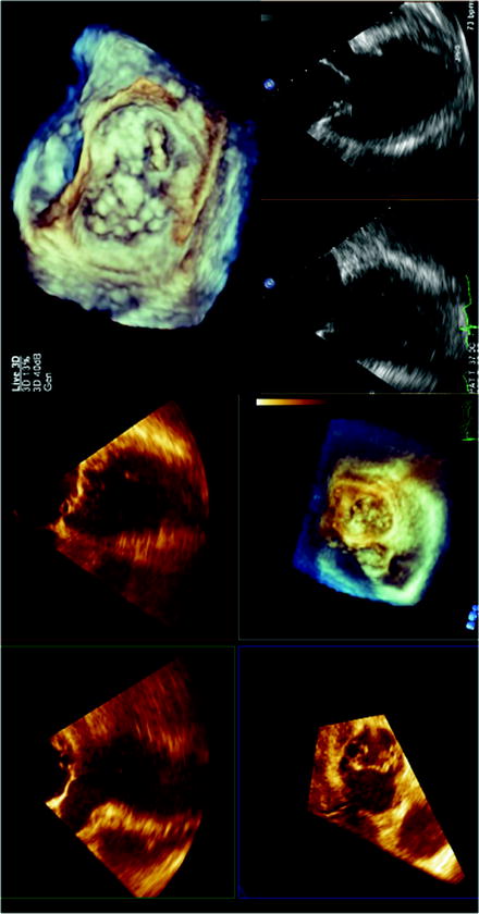
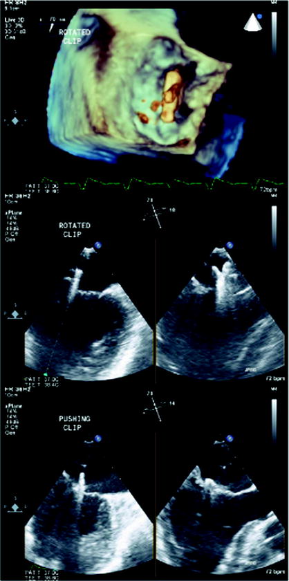
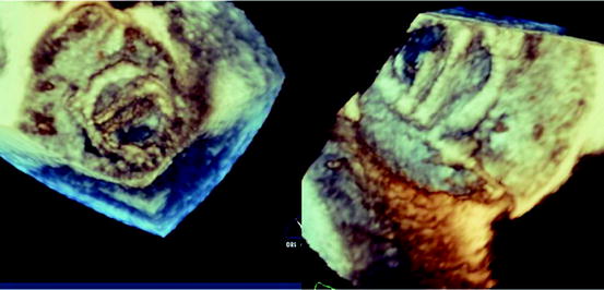

Fig. 7.12
Three-dimensional echocardiography assessment of a patient with severe mitral regurgitation. With the full-volume 3D acquisition, offline analysis of the data set accurately identifies the posterior mitral leaflet medial flail segment (left panel). Real-time 3D acquisitions also visualize the posterior medial flail segment with an enface view of the mitral valve from the left atrium, similar to the surgeon’s view of the mitral valve (top right panel). Simultaneous biplane imaging of the mitral valve allows the assessment of the flail segment in high temporal and spatial resolution, both in two-dimensional (2D) and color Doppler modes (bottom right panel). The medial location of the flail segment near the commissure makes it challenging for percutaneous treatment

Fig. 7.13
Three-dimensional echocardiography and mitral valve clip. In the mitral valve clip procedure, real-time 3D echocardiography identifies the position of the clip with respective to the mitral valve, in the enface perspective (top panel). The accurate positioning of the mitral clip often relies on simultaneous biplane imaging that more precisely defines the relationship between the arms of the clip with the valve leaflets (bottom panel)

Fig. 7.14
Three-dimensional echocardiography and percutaneous closure of paravalvular leaks. The enface view of the mitral valve obtained by real-time 3D echocardiography is especially important in the percutaneous closure of prosthetic paravalvular mitral regurgitation, as it provides the interventionist an anatomical orientation of the paravalvular regurgitation and the valve leaflets and surrounding structure. In this example, the defect is identified in the posterior aspect of the mitral prosthesis (left panel). In combination with other 2D and color Doppler views, a guidewire is successfully passed through the defect with subsequent successful deployment of the closure device (right panel)
For CS-related procedures, fluoroscopy, CT, and TEE are helpful for proper positioning of the device and evaluating the effectiveness of the intervention. Several studies have used angiography and CT to describe the in vivo anatomical relationships between mitral annulus and CS as well as CS and LCX [126–129]. These studies observed significant variance of CS to mitral annulus separation. The LCX crossed between the CS and mitral annulus in 74–97% of patients at a variable distance from the ostium of CS, depending on coronary dominance. In addition, obtuse marginal branches and posterolateral branches were also in a position to potentially be compressed by a device placed within the CS. Therefore, evaluation of the relationship between the CS/great cardiac vein and the LCX is an important factor in determining the safety of CS-based devices.
For all transcatheter valvular procedures, assessment of vascular access is important and relies on different imaging modality (Fig. 7.15). Absolute size, amount and extent of calcification, as well as tortuosity of iliac and femoral determine suitability for the procedure [130, 131]. Vascular complications are the major cause of mortality and morbidity in patients undergoing TAVI, and this should therefore be considered as transcatheter valve procedures increase in number.
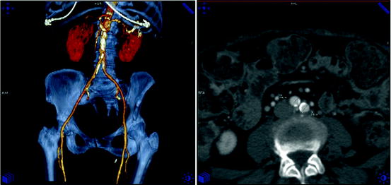

Fig. 7.15
Assessment of vascular access. Computed tomography allows assessment of the iliac anatomy including vessel diameter, calcification, and tortuosity
7.3 From Bench to Bedside: Imaging and Device Design/Development
Beyond its value for clinical decision making in the individual patient, 3D data are increasingly used for device design [132, 133]. Advances in medical imaging and computational modeling allow simulation of physiological conditions in patient-specific 3D vascular models. Such models can account for the unique features of the human circulation with appropriate 3D anatomical and physiological input data. This approach will allow prospective design of devices. Computed tomography is particularly attractive, because it acquires high-resolution volumetric data sets with sufficient temporal resolution for multiphasic analysis [134]. Along with high spatial resolution, newer state-of-the-art multi-detector CT systems have improved temporal resolutions and allow for quantification of the anatomy at multiple points in the cardiac cycle and subsequent mathematical modeling [135].
Finite element analysis is widely used in clinical research and device development. Finite element models quantitate the effects of changes in one or more of the parameters characterizing the system, including geometrical dimensions, mechanical properties, and fluid dynamics. The reliability of the results obtained through finite element modeling depends on the degree of realism achieved in modeling the physical characteristics that affect valvular biomechanics, including geometry, tissues mechanical properties, and boundary conditions due to the interaction with the surrounding tissues.
Models derived from in vivo 3D imaging provide realistic data. For example, finite element analysis using real-time 3D echocardiography examined regional mitral annular geometry and demonstrated that the nonplanar shape of the mitral annulus diminishes mitral leaflet stress [136]. Three-dimensional finite element models were also developed based on MRI of normal human aortic valve and root [137].
Computational methodology simulating valve systems is an integral part of valve design. The Food and Drug Administration in the United States and similar regulatory bodies in the European Community have established detailed guidelines for in vitro and in vivo preclinical testing of heart valve prostheses, with standardized methods and equipment in assessing fatigue, flow dynamics, and hydrodynamics of valve implants [138–140].
7.4 Conclusion
Transcatheter procedures for valvular and structural heart disease require multimodality imaging both for preoperative planning and direct guidance. Imaging modalities include 2D modalities, such as fluoroscopy and 2D echocardiography, as well as 3D imaging modalities, including CT, MRI, C-arm CT, and 3D echocardiography, which acquire volumetric data sets and allow subsequent 3D display and visualization in unlimited planes.
The data described above suggest an emerging role of 3D imaging for novel surgical and transcatheter approaches including device design. However, there is a lack of prospective data comparing the utility of different imaging modalities and demonstrating the clinical impact of image guidance in the context of these procedures [145]. Eventually, evidence-based data demonstrating favorable risk/benefit impact on clinical outcomes in controlled clinical trials are necessary.
References
1.
Iung B, Baron G, Butchart EG et al (2003) A prospective survey of patients with valvular heart disease in Europe: the Euro heart survey on valvular heart disease. Eur Heart J 24:1231–1243PubMed
2.
Mihaljevic T, Nowicki ER, Rajeswaran J et al (2008) Survival after valve replacement for aortic stenosis: implications for decision making. J Thorac Cardiovasc Surg 135:1270–1278PubMed
3.
Varadarajan P, Kapoor N, Bansal RC et al (2006) Clinical profile and natural history of 453 nonsurgically managed patients with severe aortic stenosis. Ann Thorac Surg 82:2111–2115PubMed
4.
Pai RG, Kapoor N, Bansal RC et al (2006) Malignant natural history of asymptomatic severe aortic stenosis: benefit of aortic valve replacement. Ann Thorac Surg 82:2116–2122PubMed
5.
Kapadia SR, Goel SS, Svensson L et al (2009) Characterization and outcome of patients with severe symptomatic aortic stenosis referred for percutaneous aortic valve replacement. J Thorac Cardiovasc Surg 137:1430–1435PubMed
6.
Cribier A, Eltchaninoff H, Tron C et al (2004) Early experience with percutaneous transcatheter implantation of heart valve prosthesis for the treatment of end-stage inoperable patients with calcific aortic stenosis. J Am Coll Cardiol 43:698–703PubMed
7.
Grube E, Schuler G, Buellesfeld L et al (2007) Percutaneous aortic valve replacement for severe aortic stenosis in high-risk patients using the second- and current third-generation self-expanding CoreValve prosthesis: device success and 30-day clinical outcome. J Am Coll Cardiol 50:69–76PubMed
8.
Lichtenstein SV, Cheung A, Ye J et al (2006) Transapical transcatheter aortic valve implantation in humans: initial clinical experience. Circulation 114:591–596PubMed
9.
Webb JG, Pasupati S, Humphries K et al (2007) Percutaneous transarterial aortic valve replacement in selected high-risk patients with aortic stenosis. Circulation 116:755–763PubMed
10.
Petronio AS, De Carlo M, Bedogni F et al (2010) Safety and efficacy of the subclavian approach for transcatheter aortic valve implantation with the CoreValve revalving system. Circ Cardiovasc Interv 3:359–366PubMed
11.
Krishnaswamy A, Tuzcu EM, Kapadia SR (2010) Update on transcatheter aortic valve implantation. Curr Cardiol Rep 12:393–403PubMed
12.
Gurvitch R, Wood DA, Tay EL et al (2010) Transcatheter aortic valve implantation: durability of clinical and hemodynamic outcomes beyond 3 years in a large patient cohort. Circulation 122:1319–1327PubMed
13.
Eltchaninoff H, Prat A, Gilard M et al (2010) Transcatheter aortic valve implantation: early results of the FRANCE (FRench Aortic National CoreValve and Edwards) registry. Eur Heart J 32:191–197PubMed
Stay updated, free articles. Join our Telegram channel

Full access? Get Clinical Tree


