CATHETER ABLATION OF PERSISTENT ATRIAL FIBRILLATION USING ENSITE NAVX™
Case presented by:
Question No. 1: Figure 70.1 shows the following lesion set:
A.Pulmonary vein (PV) isolation.
B.Complex fractionated electrogram (EGM) ablation.
C.Segmental ostial isolation.
D.Both A and B.
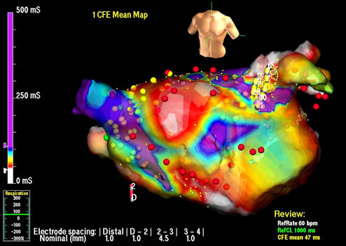
Figure 70.1. Left Atrial (LA) Geometry on the EnSite NavX™ System. Image shows a LA that has been fused with a computed tomographic (CT) reconstruction of the chamber. The torso at the top right indicates this is an anteroposterior view. Catheters are shown onscreen, including the PV mapping catheter (yellow), a quadripolar catheter in the right atrium (RA, red), and an ablation catheter (gray with a green tip). Lesions are marked in red and yellow.
Discussion
Catheter ablation of complex arrhythmia such as persistent atrial fibrillation (AF) usually requires prolonged procedures and fairly extensive ablation. The majority of centers now perform such procedures with the use of three-dimensional (3D) mapping systems, which allow manipulation of catheters without the constant use of fluoroscopy, facilitate accurate lesion placement and record lesion position, and can be used to map arrhythmia. The EnSite NavX™ system (St. Jude Medical Inc., St. Paul, MN) is one of the most popular 3D mapping systems in use.
The EnSite system passes a low-amplitude, 5.68-kHz “locator signal,” which alternates between 3 different pairs of skin patches. These are placed on the patient in orthogonal planes, so that the voltage measured from each catheter electrode can be used to locate the 3 catheter planes (x, y, and z).
At the start of the case, whilst keeping all catheters still, a “respiratory compensation” is performed, where an electrode placed on the upper abdomen to track diaphragmatic movement allows the system to compensate for respiratory movement and keep catheters relatively still onscreen through the respiratory cycle. A catheter is then selected, usually the PV mapping catheter, and is moved around the chamber of interest to collect points from the position of the electrodes to create a volume in 3D space. For catheter ablation of AF, most operators collect a LA geometry first, and only collect a RA geometry later if they intend to ablate in the RA. The acquired LA geometry is then “reassigned” in portions by clicking around parts of the geometry onscreen and using the mouse to designate parts as a PV or the LA appendage.
Using software on the mapping system called EnSite Verismo™, a CT or magnetic resonance imaging scan can be segmented to create an LA shell, which is then imported into the mapping system as shown in Figure 70.2
Stay updated, free articles. Join our Telegram channel

Full access? Get Clinical Tree


