X-RAY IMAGING SYSTEM IN THE ELECTROPHYSIOLOGY LABORATORY
Case presented by:
x-ray imaging equipment is a central piece in the electrophysiology (EP) laboratory. For many years, it has been the only way to get a view of the internal patient anatomy and the employed interventional tools. In the 1980s and 1990s, scientists developed new imaging equipment that is able to provide additional points of view of the theater of operation. This case explains how the x-ray system remains unique in its capability to deliver images of rich content for guidance during an electrophysiologic study.
Question No. 3: Is there any restriction to use x-ray images during clinical procedures?
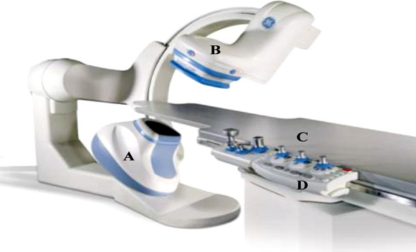
Figure 67.1. The main components of x-ray imaging equipment.
Description of x-Ray Imaging Equipment
The 2 main mechanical elements of x-ray imaging equipment are the table and the gantry.
- The table (Figure 67.1, Item A) is used to support the patient and key user interfaces (see Figure 67.1, Item D). These interfaces, which are used to operate the system, are hung on rails along the tableside. During the intervention, the tabletop (see Figure 67.1, Item C) is protected by sterile field, and the tools, such as the various catheters employed during the procedure, often lie on it.
- The gantry supports the x-ray tube on one side and the x-ray detector on the other side (see Figure 67.1, Item B). It shall maintain these 2 elements in a perfect alignment to ensure image quality and safety. The x-ray tube is a complex piece of equipment that includes a cathode and an anode. These 2 elements are in a casing under reduced atmospheric pressure. A heated filament placed in front of the cathode produces electrons, which are accelerated by the strong electrical field created between the cathode and the anode. The electrons hit the anode and their interaction with the anode material produces x-ray photons. The geometry of the anode is defined such that the spatial extent interaction zone, as seen from the detector, is reduced. So the x-ray beam can be considered as a point source. Practically, the size of the x-ray emitting source is about 1 mm2. The produced x-ray forms a fan beam. In the x-ray head, additional elements such as collimator blades are employed to control the opening of the beam to make sure that the irradiation is limited to the useful area of the anatomy.
Unique Properties of x-ray Images
Regarding the advantages of x-ray imaging, the main properties are as follows:
- Capability to perform full-field imaging. The obtained image depicts the anatomy of a patient over a large volume, which is limited only by the size of the field of view employed. Typically the field of view employed during EP procedures is 20 cm × 20 cm at the detector level, which represents about 15 cm × 15 cm at the patient level. This size suffices to include the entire heart of a patient. Moreover, the image depicts completely the section of the patient, which is in the field of view. With respect to these specificities, the x-ray image is ideal to monitor the evolutions of a patient and potentially figure out any event that may happen, like a dislodged catheter for example.
- Secondly, x-ray images can be produced in real time (<150 ms latency) at a high frame rate; 30 frames/second can be produced, which is higher than practically required to conduct an EP study. Each individual frame is obtained with a quite short pulse width, usually less than 10 ms. Thus, each image represents the state of the anatomy at a given instant. Other imaging modalities, in general, proceed by combining information taken at different instants.
- The use of radio-opaque elements such as catheter and iodine considerably enlarges the potential of this imaging modality. Indeed, these “contrast agents” are used at different places and they highlight specific anatomical structures: vessel, chambers, etc.
- The last advantage is more economical. Indeed, the most basic x-ray equipment is low-cost. Moreover, the cost of ownership is small since this type of equipment does not require complicated maintenance or supplies.
Principles of x-ray Imaging Physics
Some of the unique properties of x-ray imaging that we have listed above are a consequence of the physical properties of propagation of the x-ray photon through matter:
- The x-ray photon propagates in a straight line. Consequently, the image formed on the detector at a precise location represents the matter encountered all along the ray that goes from the point of x-ray emission to this location.
- Therefore, the intensity of the pixel is defined by the type and amount of materials (tissue, contrast agent, interventional tool) encountered along this path. Indeed, the attenuation of an x-ray beam is variable as a function of the atomic number and the density of the traversed tissue. This total attenuation, which varies from place to place, is, in the end, responsible for the contrast of the image. Figure 67.2 shows a typical x-ray image obtained in an EP lab.
- A first side effect shall be considered: the attenuation of the x-ray beam by the matter produces secondary x-ray photons, which are produced at the precise place where the ray is attenuated. These secondary photons are emitted in all directions. These radiations are called scatter. As the source of this emission and the direction of this emission cannot be controlled, they can reach any point in the lab except if adequate protection measures are taken, such as lead aprons or radiation shields. This equipment contains elements with high atomic numbers that attenuate the x-ray beam and protect the catheterization lab team.
- A second side effect is the irradiation delivered to the patient. This irradiation is necessary to ensure that a contrasted image is formed. Above some thresholds, these ionizing radiations may induce dermatological disease such as erythema and increase the stochastic risk of cancer for the population.
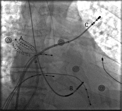
Figure 67.2. Typical x-ray image in an EP lab. Labels A, B, and C point out typical catheters used during the procedure. These catheters include radio-absorbing material and offer a good contrast versus the biological tissue. One can also see the contrast between the heart and the lung. The attenuation of the x-ray beam in the lung is inferior to the heart area because the lungs are filled with air, the density of which is inferior to regular anatomical tissue.
Geometrical Characteristics of x-ray Imaging
Stay updated, free articles. Join our Telegram channel

Full access? Get Clinical Tree


