Pacemaker Timing Cycles and Special Features
Medical College of Virginia/VCU School of Medicine, Richmond, VA, USA
Introduction
Since the development of implantable cardiac pacemakers in 1960, the features and functions built into these devices has continued to change as the cardiac field evolves. Pacemakers have become highly complex due to the addition of multiple specialized features in an attempt to treat different cardiac conditions, such as sick sinus syndrome with or without chronotropic incompetence, cardioinhibitory vasovagal syndrome, and paroxysmal atrial arrhythmias, and avoid some adverse effects of chronic pacing, such as heart failure, induction of atrial and supraventricular arrhythmias, etc. Thus, a deep understanding of the different pacing modes, pacemaker timing cycles, and special features is paramount to identify normal versus abnormal pacemaker function.
Timing cycles are based on cardiac events such as atrial- and ventricular-sensed and -paced events. Thus, appropriate pacemaker function depends on the ability of these devices to properly recognize atrial- and ventricular-sensed events. Timing cycles include different blanking periods, refractory periods, and intervals. The number and complexity of these timing cycles depend and vary based on the number of leads, pacing mode, and/or rate sensor. Accurate examination of timing cycles and pacemaker behavior requires device interrogation and analysis of “event markers” as they provide the actual pacemaker interpretation and response to different cardiac signals. For the rest of the chapter, the following abbreviations will be used to describe common pacemaker marker events: “P” native atrial depolarization, “A” an atrial-paced event, “R” a native ventricular depolarization, and “V” a ventricular-paced event.
Pacing Nomenclature
A three-letter code describing the basic function of the various pacing systems was first proposed in 1974 by a combined task force from the American Heart Association and the American College of Cardiology. As pacemakers have become more complex with multiple features, the basic function of pacemakers is now denoted as a generic five-letter code (Table 6.1).1 However, this five-letter code does not describe the specific or unique functional characteristics of each device.
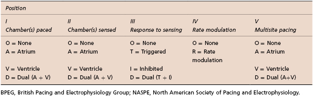
Table 6.1 Revised NASPE/BPEG generic code for bradycardia, adaptive-rate, and multisite pacing (Source: Modified from Bernstein 2002.1 Reproduced with permission of John Wiley & Sons Ltd.)
The first position reflects the chamber or chambers in which stimulation occurs. “A” refers to the atrium, “V” indicates the ventricle, and “D” denotes dual chamber (or both atrium and ventricle).
The second position refers to the chamber or chambers in which sensing occurs. The letter designators are the same as those for the first position. Some manufacturers also use “S” in both the first and the second positions to indicate that the device is capable of pacing only a single cardiac chamber.
The third position refers to the mode of sensing, or how the pacemaker responds to a sensed event. An “I” indicates that a sensed event inhibits the pacing stimulus and causes the pacemaker to reset or re-initiate one or more timing cycles. A “T” means that an output pulse is triggered in response to a sensed event. Similar to the first two positions, a “D”, means that there are dual modes of response. This designation is restricted to dual chamber systems. An event sensed in the atrium inhibits atrial output but triggers ventricular output, also referred to as P-synchronous pacing. Unlike the single chamber triggered mode, in which a pacing output is triggered immediately on sensing, a delay occurs between the sensed atrial event and the triggered ventricular pacing output to mimic the normal PR interval. Finally, if a native ventricular signal or R wave is sensed, it inhibits ventricular output and possibly even atrial output, depending on where sensing occurs.
The fourth position of the code reflects sensor rate modulation. An “R” indicates that the pacemaker incorporates a sensor to control the rate independently of intrinsic electrical activity of the heart, so-called rate-modulated pacing.
The fifth position indicates whether multisite pacing is not present (O) or present in the atrium (A), ventricle (V), or both (D). Multisite pacing is defined for this purpose as stimulation sites in both atria, both ventricles, more than one stimulation site in any single chamber, or any combination of these. The letter designators are the same as those for the first position. This fifth position has become relevant with the introduction of biventricular devices.
Pacing Modes
Pacing modes have evolved with technology and each pacing mode has specific and general indications, as well as unique advantages and disadvantages (Table 6.2). The timing cycles of each of these pacing modes are discussed in the following section.
| Pacing mode | Indication/advantages | Disadvantages |
|---|---|---|
| Asynchronous pacing (AOO, VOO, DOO) | Pacemaker-dependent patients exposed to noise (e.g. electrocautery during surgery) Avoids oversensing and asystole | Pacing regardless of intrinsic events Potential risk for arrhythmia induction |
| Single chamber inhibited pacing (AAI, VVI) | AAI—sick sinus syndrome with intact AV node; preserves AV synchrony VVI—atrial fibrillation with slow VR and single-lead ICDs AAI/VVI require a single lead and increase battery longevity | AAI lacks ventricular pacing in the event of intermittent AV block VVI is associated with AV dyssynchrony (manifests as pacemaker syndrome). VVI has a higher incidence of atrial arrhythmias30 |
| Single chamber triggered without inhibited pacing (AAT, VVT) | Historically used in pacemaker-dependent patients to assure pacing with lower probability of arrhythmia induction | Shortens battery life due to chronic pacing |
| DDD, DDDRV (CRT) | Preserves AV synchrony (less pacemaker syndrome) Low incidence of atrial arrhythmias and improved hemodynamics | Requires at least a two chamber lead system and has a shorter battery longevity |
| DDI | Functions as two different pacemakers (AAI and VVI) Used as mode switch to avoid tracking atrial tachyarrhythmias | Same as DDD Possible AV dyssynchrony and pacemaker syndrome (does not track atrial sensed events) |
| VDI | Used for mode switch purposes as it functions as a VVI (non-tracking pacing mode) with additional atrial sensing | Similar to VVI, as it is associated with AV dyssynchrony and potential atrial arrhythmias |
| VDD | Appropriate sinus node function with AV node disease, e.g. MDT RV lead model 5038; dual chamber with high atrial pacing threshold to minimize battery depletion | Lack of atrial pacing Potential AV dyssynchrony at lower rate limit |
| DVI | Severe sinus bradycardia/standstill and atrial lead malfunction (oversensing) | Asynchronous atrial pacing Potential AV dyssynchrony For both atrial and ventricular stimuli to be inhibited, the sensed R wave must occur during the VAI |
For acronyms, see Table 6.3.
Table 6.2 Indications, advantages, and disadvantages of commonly used pacing modes (Source: Modified from Huizar JF, Kaszala K, Ellenbogen KA. Cardiac pacing modes and terminology. In: Sakena S, Camm AJ, eds. Electrophysiological Disorders of the Heart, 2nd Ed. Philadelphia, PA: Elsevier Saunders, 2012: 441–456. Reproduced with permission of Elsevier.)
Single or Dual Chamber Asynchronous Pacing (AOO, VOO, DOO)
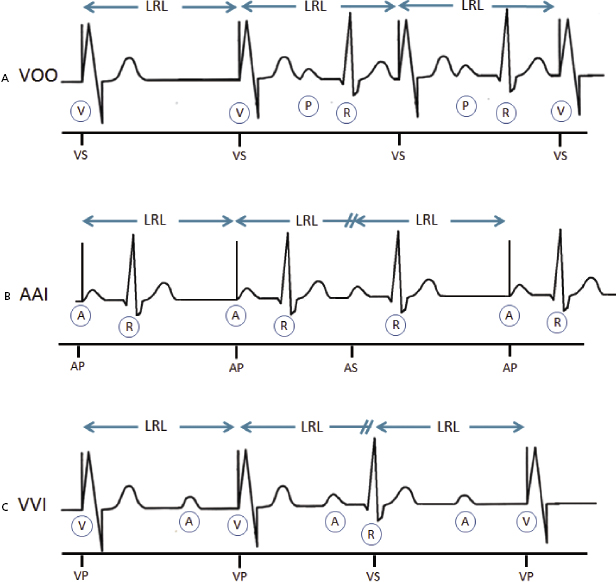
Ventricular asynchronous (VOO) pacing is the simplest of all pacing modes because there is neither sensing nor mode of response, and lower rate limit (LRL) is the only timing cycle available (Figure 6.1A). Atrial asynchronous (AOO) pacing behaves exactly like VOO, but pacing occurs in the atrial chamber. Dual chamber or sequential atrioventricular (AV) asynchronous pacing (DOO) occurs at the LRL in the atrium, followed by the ventricle after completion of the atrioventricular interval (AVI), irrespective of any cardiac events. This pacing mode may be transiently used in pacemaker-dependent patients to avoid inappropriate pacing inhibition during interventions or surgeries associated with noise (Table 6.2).
Single Chamber (Atrial or Ventricular) Inhibited Pacing (AAI, VVI)
Pacemakers with an atrial lead can be programmed AAI, whereas devices with a ventricular lead can be programmed VVI (Figure 6.1B,C). AAI pacing mode denotes atrial pacing (A), atrial sensing (A), and inhibition (I) of pacing output in response to an atrial-sensed event (P wave), whereas VVI pacing mode indicates ventricular pacing (V), ventricular sensing (V), and inhibition (I) of pacing output in response to a ventricular sensed event (R wave). Atrial (AAI) and ventricular inhibited (VVI) pacing modes incorporate sensing on the atrial or ventricular channel, whereas pacemaker stimuli are inhibited by a sensed atrial or ventricular event, respectively.
Single Chamber Triggered Mode (without Inhibition) Pacing (AAT, VVT)
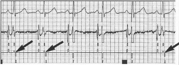
Single chamber triggered mode pacing (AAT, VVT) will deliver pacing output every time a native event is sensed or the LRL interval is reached. As it deforms the native signal, it may compromise electrocardiogram (ECG) interpretation. This pacing mode can serve as an excellent marker for the site and time of sensing within a complex in an ECG tracing. Historically, this pacing mode was used to prevent inappropriate inhibition from oversensing in a patient without a stable native escape rhythm. In contrast to asynchronous pacing (AOO or VOO), this pacing mode is less likely to induce arrhythmias as it will pace within refractoriness of myocardial tissue when the intrinsic cardiac event is sensed. However, arrhythmias could be initiated if non-cardiac signals are inappropriately sensed.
Dual Chamber Pacing and Sensing with Inhibition and Tracking (DDD)
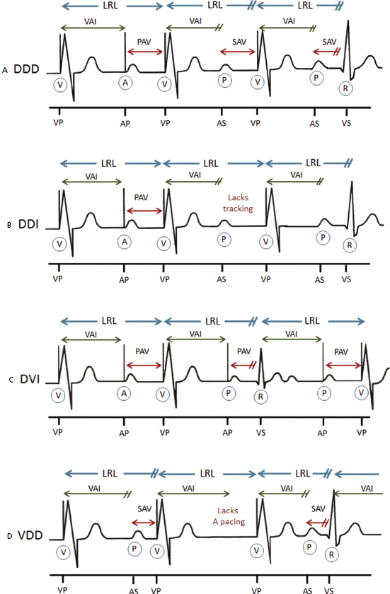
This can also be referred to as AV sequential (D) pacing, dual chamber sensing (D) with inhibition, and P-synchronous pacing (D). DDD mode refers to atrial and ventricular pacing and sensing with dual response (inhibited and triggered pacing) to an intrinsic atrial-sensed event or a ventricular-sensed event (Figure 6.2A). In this pacing mode, the pacemaker will pace both the atrium and the ventricle (AV sequential pacing), with programmed AV delay if the intrinsic atrial and ventricular rates are below the LRL. If the atrial rate is slower than the LRL, the device will pace the atrium while inhibiting ventricular pacing if an intrinsic ventricular event is sensed within a pre-determined AV delay. If an atrial-sensed event is faster than the LRL without an intrinsic ventricular event, the pacemaker inhibits atrial pacing but triggers ventricular pacing (P-synchronous pacing) after a pre-determined AV delay (Figure 6.2A). However, tracking an atrial-sensed event will only occur up to a programmable maximum tracking rate (MTR), which will prevent the pacemaker from tracking atrial dysrhythmias beyond a certain rate (see “Upper rate behavior”). Finally, pacing will be completely inhibited if the intrinsic atrial and ventricular rates are above the LRL (unless a short AV delay is programmed). This pacing mode is the most commonly used in dual chamber devices (DDD or DDDR) and biventricular pacemakers (DDDOV or DDDRV).
Dual Chamber Pacing and Sensing with Inhibition But without Tracking (DDI)
This can also be referred to as AV sequential pacing (D) with dual chamber sensing (D) and inhibition (I) without P-synchronous pacing. This pacing mode is similar to DDD without tracking atrial-sensed events or P-synchronous pacing. Because P wave tracking does not occur with the DDI mode, the ventricular paced rate is never greater than the programmed LRL regardless of the atrial rate (Figure 6.2B). AV sequential pacing will only occur at LRL if no intrinsic ventricular event is sensed after atrial pacing. The main advantage and indication of DDI is in the presence of paroxysmal atrial arrhythmias such as atrial fibrillation and/or flutter (Table 6.2). This pacing mode is commonly programmed as a mode switch to avoid tracking of these atrial tachyarrhythmias.
Ventricular Pacing with Inhibition and Dual Chamber Sensing (VDI)
VDI pacing mode gives ventricular pacing (V), while sensing both chambers (D), and inhibits ventricular pacing if an intrinsic R wave is sensed. This pacing mode allows atrial sensing but does not provide P-synchronous pacing (non-tracking mode). In addition, it lacks atrial pacing for which it cannot provide AV sequential pacing. Thus, in sinus rhythm, there is AV dissociation in VDI mode regardless of rate. It is an alternative pacing mode in patients with atrial fibrillation and flutter, and it is available as a mode switch feature in some pacemakers.
Atrioventricular Sequential, Ventricular Inhibited Pacing (DVI)
DVI mode provides pacing in both the atrium and the ventricle (D), while only sensing and inhibiting pacing in the ventricle (V). Pacing is only inhibited (I) and reset by ventricular-sensed events, but ignores all intrinsic atrial complexes. The difference between DVI and DDI is that the former lacks atrial sensing. Thus, DVI commonly demonstrates asynchronous atrial pacing at LRL (Figure 6.2C). Similarly to DDI, ventricular pacing will never be greater than programmed LRL when in DVI mode due to the lack of atrial sensing. DVI was used in first-generation pacemakers but it is still programmable in many available dual chamber pacemakers. Nowadays, DVI can be used in patients with marked sinus bradycardia or atrial arrest with atrial lead malfunction (oversensing) in which AV synchrony is desired (Table 6.2).
Ventricular Pacing, Dual Chamber Sensing with P-Synchronous Ventricular Pacing and Inhibition (VDD)
VDD mode delivers ventricular pacing only (V), senses both the atrium and ventricle (D), while it inhibits ventricular pacing (I) and tracks (T) atrial-sensed events (P-synchronous pacing; Figure 6.2D). The most common use of this pacing mode is in devices with a single-pass lead which integrates an atrial-sensing electrode with a ventricular-pace/sense electrode. This system has been used in subjects with appropriate sinus node function who require ventricular back-up pacing due to high-degree AV block or during biventricular pacing. It can also be used in dual chamber pacemakers with appropriate sensing of normal sinus node with high atrial pacing threshold in an attempt to maximize battery longevity2,3 (Table 6.2).
Timing Cycles
A given timing period or interval can continue until it completes its cycle; completion results in either the release of a pacing stimulus or the initiation of another timing cycle. Alternatively, a given period or interval can be reset by an intrinsic cardiac event, at which point it restarts the timing period again or initiates another timing period. Each portion of the pacemaker timing cycle should be considered in milliseconds (a thousandth of a second) and not in beats per minute (bpm). Although thinking of the patient’s pacing rate in paced beats per minute may be easier, portions of the timing cycle are too brief to be considered in any unit other than milliseconds.
Blanking and Refractory Periods
All pacing modes that can sense cardiac events must include blanking and refractory periods in their basic timing cycle. The presence or absence of these periods depends on the pacemaker system as well as the pacing/sensing mode. These periods are essential to the appropriate pacemaker function as they prevent sensing of known but clinically inappropriate signals, such as the evoked potential and repolarization. The blanking and refractory periods of a pacemaker are analogous to the absolute and relative refractory periods of the heart, respectively, during which a stimulus delivered to the heart is ineffective because the myocardium is already depolarized and a subsequent depolarization cannot occur until the resting membrane potential is re-established. The blanking period (BP) is equivalent to an absolute refractory period, during which the sensing amplifier is “off” or “blind” to any cardiac event and thus cannot be detected. Once this period ends, the sense amplifier becomes alert and is receptive to the detection of native signals. The refractory period (RP) is comparable to the relative RP, when cardiac events can be sensed, but it usually does not trigger or reset timing cycles. In contrast to BPs, RPs allow detection of rapid cardiac events (Figure 6.3). In dual chamber pacing, BP is also used to prevent cross-talk (see “Atrioventricular interval, cross-talk, and safety pacing”).
Timing Cycles Based on Pacing Mode
Cardiac events and timing cycles are based on a single, dual, or biventricular pacemaker systems and programmed pacing modes (Table 6.3).
| Cardiac events/timing cycles (abbreviation) | Description |
|---|---|
| Single chamber (atrial or ventricular) pacemaker | |
| Atrial sensed event (P/AS) | Sensed a native Atrial depolarization (P wave) |
| Atrial paced event (A/AP) | Delivered Atrial Pacing output |
| Ventricular sensed event (R/VS) | Sensed native Ventricular depolarization (QRS complex) |
| Ventricular paced event (V/VP) | Delivered Ventricular Pacing output |
| Atrial blanking period (ABP) | Atrial-sensing amplifier is “blind” and will not detect or respond to any atrial-sensed event |
| Ventricular blanking period (VBP) | Ventricular-sensing amplifier is “blind” and will not detect or respond to any ventricular-sensed event |
| Atrial refractory period (ARP) | An atrial sensed event will be noted but ignored, without affecting the pacemaker timing cycle |
| Ventricular refractory period (VRP) | A ventricular-sensed event will be noted but ignored, without affecting the pacemaker timing cycle |
| Lower rate limit (LRL) | Minimum pacing rate |
| Upper rate limit (URL) | Maximum pacing rate |
| Maximum sensor rate (MSR) | Maximum pacing rate by rate-modulated sensor |
| Dual chamber (atrial and ventricular) pacemaker | |
| Atrioventricular sequential pacing (AV) | Atrial-paced event followed by paced ventricular event |
| P-synchronous V pacing (PV) | Atrial-sensed event followed by paced ventricular event |
| VA interval (VAI) | Interval from ventricular-sensed or -paced event to atrial-paced event |
| PR | Atrial-sensed event followed by ventricular-sensed event (native intrinsic atrial and ventricular events) |
| AR | Atrial-paced event followed by ventricular-sensed event |
| AV interval or delay (AVI) | Programmed atrioventricular pacing interval |
| Paced AV interval (paced AVI) | AV interval/delay from atrial-paced event (A) to ventricular-paced event (V) |
| Sensed AV interval (sensed AVI) | AV interval/delay from atrial-sensed event (P) to ventricular-paced event (V) |
| Maximum or upper tracking rate (MTR) | Maximum ventricular pacing rate allowed in response to high sensed atrial rates |
| Post-atrial ventricular blanking period (PAVB) | Period where ventricular sensing is “off” after an atrial-paced event |
| Post-ventricular atrial blanking period (PVAB) | Period where atrial sensing is “off” after a ventricular-paced or -sensed event |
| Post-ventricular atrial refractory period (PVARP) | Period after ventricular event where the device can sense an atrial event but does not track it |
| Total atrial refractory period (TARP) | Sum of AVI and PVARP |
| Rate-modulated AV delay [RMAVD; also referred to as rate-responsive AV delay (RRAVD)] | AV delay that adjusts by shortening as the rate increases. |
| Cardiac resynchronization therapy/pacemakers | |
| RV post-atrial ventricular blanking period (RV-PAVB) | Period where RV sensing is “off” immediately after atrial pacing (avoids oversensing atrial signals) |
| LV post-atrial ventricular blanking period (LV-PAVB) | Period where LV sensing is “off” immediately after atrial pacing (prevents oversensing atrial signals) |
| RV refractory period (RVRP) | A RV-sensed event may be noted but ignored, without affecting the pacing timing cycle |
| LV refractory period (LVRP) | A LV-sensed event may be noted but ignored, without affecting LV pacing timing cycle |
| LV protection period (LVPP) | Period after a ventricular-paced or -sensed event that prevents inappropriate pacing during the vulnerable period |
| Biventricular pacing interval or LV offset | Timing gap between RV and LV pacing (RV–LV interval) |
Table 6.3 Acronyms and description of cardiac events and timing cycles in a single chamber, dual chamber, and biventricular pacemakers/devices (Source: Modified from Huizar JF, Kaszala K, Ellenbogen KA. Cardiac pacing modes and terminology. In: Sakena S, Camm AJ, eds. Electrophysiological Disorders of the Heart, 2nd Ed. Philadelphia, PA: Elsevier Saunders, 2012: 441–456. Reproduced with permission of Elsevier.)
Asynchronous single chamber pacing modes (AOO, VOO) pace the assigned chamber at LRL (only timing cycle), which cannot be reset by any intrinsic cardiac event. Dual chamber or AV sequential asynchronous (DOO) pacing has an equally simple timing cycle. The interval from atrial to ventricular pacing (AVI) and the interval from ventricular pacing to the subsequent atrial pacing [ventriculoatrial interval (VAI)], also referred to as atrial escape interval (AEI), are both fixed. These intervals are never reset, because the pacing mode is insensitive to any atrial or ventricular activity.
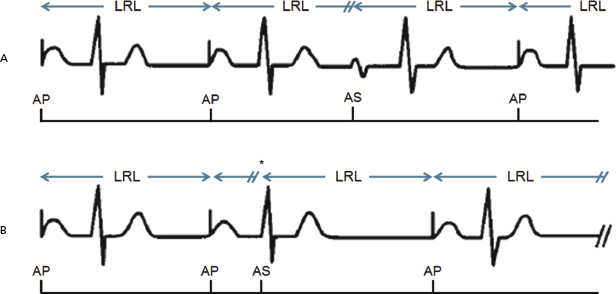
Atrial inhibited pacing (AAI) consists of the atrial blanking (ABP), atrial refractory period (ARP), and LRL (AA interval). ABP and ARP initiate after a paced or sensed atrial event in order to avoid oversensing of evoked potentials, atrial repolarization, or ventricular depolarization. During ABP, any signals are not sensed. In contrast, ARP allows sensing of rapid atrial signals (included in the counter); however, these signals are ignored as they will not reset timing cycles (Figure 6.4A). Atrial pacing will occur after the LRL times out, but pacing will be inhibited and LRL reset after an atrial event is sensed (Figure 6.5A). Nevertheless, an A–A interval (programmed LRL) could be inappropriately reset by a far-field R wave oversensing in the atrial channel after ABP and ARP have expired (Figure 6.5B).
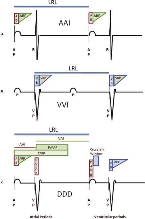
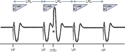
Ventricular inhibited (VVI) pacing, the ventricular counterpart of AAI pacing, incorporates the same timing cycles, with the obvious differences that pacing and sensing occur in the ventricular channel and pacing output is inhibited by a sensed ventricular event (Figure 6.4B). A ventricular-paced or -sensed event initiates a ventricular blanking period (VBP) and a ventricular refractory period (VRP) during which the pacemaker will not reset the ventricular timer or LRL after a ventricular-sensed event (Figure 6.6).
DDD pacing mode embraces all timing cycles described on AAI and VVI pacing modes.
In addition, LRL is divided into two sections: the VAI or AEI, and the AVI, as depicted in Figure 6.4C. The VAI initiates after a ventricular-sensed or -paced event and does not terminate until an atrial event is sensed; however, atrial pacing will occur if the VAI expires without sensing an intrinsic atrial event. The AVI begins with an atrial-sensed or -paced event and extends to a ventricular event. Similarly, ventricular pacing will occur if the AVI elapses without the presence of an intrinsic ventricular event.
Furthermore, a sensed or paced atrial event initiates an ABP followed by an ARP (Figure 6.4C). During the ABP and ARP, the atrial channel is refractory and will not reset timing cycles even in the presence of another native atrial event. Ventricular pacing occurs only at the end of the AVI or later [see “Upper rate behavior” (Wenckebach-like behavior)]. A sensed or paced ventricular event initiates a VBP followed by a VRP. VBP and VRP prevent sensing of the evoked potential and the resultant T wave on the ventricular channel of the pacemaker. After the blanking period, the ventricular-sensing channel is again operational, or “alert.” If atrial activity is not sensed by the time of the expiration of the VAI, atrial pacing occurs, followed by the AVI. If intrinsic ventricular activity occurs before the VAI is completed, this timing cycle is reset.
A sensed or paced ventricular event also initiates a refractory period on the atrial channel, referred to as the post-ventricular atrial refractory period (PVARP). The PVARP is designed to prevent ventricular tracking of a retrograde P wave (see “PVARP and pacemaker-mediated tachycardia”). The combination of the PVARP and the AVI establishes the total atrial refractory period (TARP). TARP is the limiting factor for the upper rate limit (URL) or so-called MTR in P-synchronous dual chamber pacing modes, which instructs the pacemaker what the maximum atrial-sensed rate is to be tracked by ventricular pacing (see section: “Upper rate behavior” and “Total and post-ventricular atrial refractory periods”).
DDI pacing mode includes the identical timing cycles described for DDD mode. DDI mode differs from DDD mode in the response to atrial sensing, as it cannot trigger ventricular pacing after atrial-sensed events (it lacks P-synchronous ventricular pacing; Figure 6.3B).
In contrast to DDD pacing mode, DVI pacing mode cannot trigger ventricular pacing in response to atrial events since it lacks atrial sensing. Furthermore, DVI pacing mode lacks timing cycles that involve atrial sensing, such as ABP, ARP, post-ventricular atrial blanking period (PVAB) and post-ventricular atrial refractory period (PVARP), and TARP. Thus, DVI pacing mode commonly demonstrates asynchronous atrial pacing at LRL (Figure 6.3C). For instance, a sensed R wave during the VAI (ventricular ectopy) will reset the VAI, delaying atrial pacing in DVI mode.
VDD pacing mode lacks atrial pacing (Figure 6.3D). Thus, the post-atrial ventricular blanking period (PAVB) and cross-talk window (found on DDD and DDI pacing modes) are absent. A sensed atrial event initiates the AVI. If an intrinsic ventricular event occurs before termination of the AVI, ventricular output is inhibited, and the LRL timing cycle is reset. Similarly, a P-synchronous ventricular pacing at the end of the AVI will reset the LRL. A ventricular-sensed or -paced event will initiate PVARP and VAI. If no atrial event occurs, the pacemaker escapes with a paced ventricular event at the LRL (pacemaker behaves as VVI in the absence of a sensed atrial event at the base rate).
Overall, pacemaker behavior depends on the programmed pacing mode and base rate behavior. However, other programmable features may affect device behavior (Table 6.4). These are discussed throughout the chapter.
| Device behavior | Pacing features/algorithms |
|---|---|
| Intrinsic rate slower than programmed base rate | Rate/scan hysteresis Sleep or rest rate Sinus preference Special algorithms (e.g. +PVARP after PVC) Atrial-based timing in DDD after PVC |
| Base rate (AV,AR) higher than programmed rate | Sensor-driven rate Rate smoothing Fallback Mode-switching response rate Sudden bradycardia/rate drop response Atrial overdrive suppression Special algorithms (e.g. +PVARP after PVC) Magnet mode rate Atrial and ventricular auto-threshold test |
| Intrinsic AVI (PR,AR) longer than programmed paced or sensed AVI | AV or PV hysteresis Algorithms to allow intrinsic AV conduction Sinus rate with intact AV conduction exceeding MTR |
| Paced or sensed AVI shorter than programmed paced or sensed AVI | Rate-modulated or dynamic AV delay Negative AV or PV hysteresis Safety pacing Managed ventricular pacing (MVP, AAI  DDD) DDD)Non-competitive atrial pacing (NCAP) Auto-threshold test |
| Loss of atrial tracking (DDD) | Automatic mode switch MSR > MTR |
*Note: device behaviors are not necessarily continuous; the effects can be seen on a single cycle or during a brief period.
PVC, premature ventricular contraction; for other acronyms, see Table 6.3.
Table 6.4 Features that may affect device behavior*
Atrioventricular Interval, Cross-Talk, and Safety Pacing
AVI refers to a programmable interval initiated by a sensed or paced atrial event (P or A event, respectively) followed by ventricular pacing after the time interval expires (Figure 6.7). If a ventricular event is sensed before the time interval is completed, the AVI will terminate and initiate the VAI. At the beginning of the AVI, the atrial channel is briefly blind (ABP) followed by an ARP to allow detection of abnormal rapid atrial signals during the AVI (Figure 6.8).
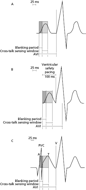
The potential exists for signals other than those of intrinsic ventricular activity to be sensed during the AVI and inhibit ventricular output. Thus, atrial pacing artifact inappropriately sensed by the ventricular-sensing amplifier could result in ventricular pacing inhibition, referred to as cross-talk. To prevent cross-talk, atrial pacing also initiates a PAVB to avoid ventricular oversensing of atrial-paced events (Figure 6.7B). In DDD pacemakers, this blanking period may be programmable, ranging from 12 to 125 ms. The blanking period is traditionally of short duration because it is important for the ventricular-sensing circuit to be returned to the “alert” state relatively early during the AVI so that intrinsic ventricular activity can inhibit pacemaker output if it occurs before the AVI ends.
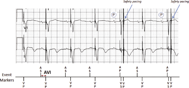
Even though the atrial pacing artifact is effectively ignored because of the PAVB, the trailing edge of the atrial pacing artifact occurring after the PAVB can occasionally be sensed on the ventricular channel. In a pacemaker-dependent patient, inhibition of ventricular output by cross-talk results in ventricular asystole. To prevent such a catastrophic outcome, DDD pacing mode has a safety mechanism called the “ventricular triggering period” or the “cross-talk sensing window” (Figure 6.7C). If activity is sensed on the ventricular-sensing amplifier during the AVI immediately after the PAVB, it is assumed that cross-talk cannot be differentiated from intrinsic ventricular activity. Sensing during this window will result in a triggered rather than an inhibited output. This early ventricular pacing typically occurs with an AVI of 100–120 ms (can be programmed to 50–150 ms in some pacemakers) to prevent asystole. This has been referred as “safety pacing” or “non-physiological AV delay” or the “110-ms phenomenon.” Safety pacing is designed to prevent ventricular asystole if cross-talk were to occur in a pacemaker-dependent patient. Occurrence of cross-talk and safety pacing should be suspected if AV pacing is noted at a shorter than programmed AVI on ECG (Figure 6.9). Elimination of cross-talk can be achieved by extending the PAVB, decreasing atrial output, or reducing the ventricular sensitivity. If true intrinsic ventricular activity occurs during the cross-talk sensing window, safety pacing will result in a fusion beat. Although the safety pacing phenomenon accompanying a late-cycle premature ventricular contraction (PVC) has been interpreted as a sensing failure, it actually reflects normal sensing.
After the blanking period and the cross-talk sensing window have timed out, the ventricular-sensing circuit returns to the alert status, in which a detected event terminates the AVI with subsequent inhibition of ventricular pacing.
Differential Atrioventricular Interval
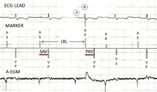
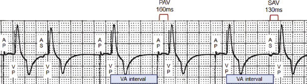
The differential AVI is an attempt to provide an intra-atrial conduction time of equal duration whether atrial contraction is paced or sensed. The PV interval initiated with atrial sensing, referred to as “sensed AV delay (SAV),” commences only when the atrial depolarization is detected by the pacemaker, and commonly occurs 20–60 ms after the onset of the P wave on a surface ECG. Conversely, the AVI initiated with atrial pacing, referred to as “paced AV delay (PAV),” commences immediately with the pacing artifact. Therefore, in general, the AVI that follows a sensed atrial event should be shorter than one that follows a paced atrial event in an effort to achieve similar functional AVIs (Figure 6.10). Most dual chamber pacemakers allow the paced and sensed AV delays to be programmed independently with differences of up to 100 ms. Nonetheless, a differential AVI is preset or automatically calculated in other pacemakers (Figure 6.11).
Dynamic or Rate-Adaptive Atrioventricular Interval
Pacemaker algorithms may be used in dual chamber pacing modes to shorten the AVI as the atrial rate increases, either by an increase in sinus rate or sensor-driven paced rate (Figure 6.12). Dynamic AVI is intended to optimize cardiac output by mimicking the normal physiological decrease in the PR interval that occurs in the normal heart as the atrial rate increases. The rate-related shortening of the AVI can be useful to improve atrial sensing, and to enhance atrial tracking at faster rates by shortening the TARP (AVI + PVARP) and thereby extending the atrial-sensing window.
The rate-adaptive AVI algorithm varies according to the pacemaker and manufacturer. A common method allows linear shortening of the AVI from a programmed baseline AVI to a programmed minimum AVI. Another method allows a limited number of stepwise shortenings of the AVI, which may or may not be programmable.
Atrioventricular Interval Hysteresis
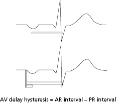
The term AVI hysteresis has been used variably, but most commonly describes alterations in the paced AVI relative to the patient’s intrinsic AV conduction. For example, a longer paced AVI is permitted to allow maintenance of intrinsic AV conduction, previously referred to as positive hysteresis. The term positive AV hysteresis is largely of historic significance. Nowadays, several algorithms have been developed to avoid the deleterious effects of chronic right ventricle (RV) pacing (see “Algorithms to minimize right ventricular pacing”), including abnormal ventricular activation sequence and heart failure symptoms.4 In contrast, the term negative hysteresis can still be found in a few contemporary devices. This feature is intended to temporarily shorten the AVI (to 10–150 ms) if an intrinsic ventricular event is sensed in the AVI, which could be relevant in biventricular pacing and hypertrophic cardiomyopathy.
Ventriculoatrial Interval (VAI)
The VAI interval is only present in dual chamber pacing modes, regardless of tracking feature (DDD, DDI, DVI). This interval has been also called “atrial escape interval (AEI).” The VAI is initiated after an intrinsic ventricular event is sensed (prior to completion of the AVI) or paced (after the AVI expires). This interval will be terminated prematurely if an intrinsic atrial event occurs, which in turns initiates an AVI. However, this interval is reset/re-initiates if an intrinsic ventricular event is sensed. If no atrial- or ventricular-sensed event occurs during the VAI, an atrial pacing stimulus will occur after conclusion of this interval. In most pacemakers, the VAI is fixed and non-programmable, and together with the AVI, determines the LRL. The VAI is variable in (1) rate-modulated pacing modes [the sensor-indicated rate (SIR) will increase based on VAI shortening]; and (2) atrial-based timing (see “Rate-modulated pacing” and “Base rate behavior”).
Total and Post-Ventricular Atrial Refractory Periods
The post-ventricular atrial refractory period (PVARP) is a programmable interval in dual chamber pacing modes with atrial sensing (DDD, DDI, VDD), initiated after a sensed or paced ventricular event. This period is intended to avoid inappropriate tracking of sensed signals due to ventricular repolarization or retrograde P waves. If an atrial event occurs during PVARP, timing cycles (VAI, LRL) are not reset. Nevertheless, sensing of atrial signals during PVARP allows proper mode switch (non-tracking pacing mode) when atrial fibrillation, flutter, or tachycardia occurs (see “Mode switch”).
In a P-synchronous pacing mode, PVARP should be extended to include retrograde P wave if VA conduction is present to avoid pacemaker-mediated tachycardia (PMT, also referred to as endless-loop tachycardia; see “Pacemaker-mediated tachycardia”). Appropriate PVARP programming is also important to reduce tracking of atrial arrhythmias.
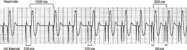
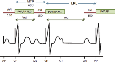
Total atrial refractory period (TARP) is the sum of the AVI and PVARP. TARP is the limiting factor for the URL (maximum tracking or sensor rate) in which the pacemaker can pace and track P waves or atrial-sensed events (Figure 6.13). For example, if the AVI is 150 ms and the PVARP is 250 ms, the TARP is 400 ms or 150 bpm. In this case, a 250-ms PVARP initiates after a ventricular-paced event, and only after this interval has expired can an atrial event be sensed. If an atrial event is sensed immediately after termination of the PVARP, it initiates an AVI of 150 ms. After the AVI ends, a paced ventricular event will occur in the absence of an intrinsic R wave, resulting in a V–V cycle length of 400 ms or 150 bpm. Thus, programming a long PVARP limits the MTR and maximum sensor rate (MSR).
Dynamic PVARP
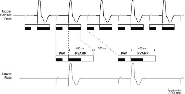
In current pacemakers, a heart rate or SIR determined dynamic PVARP adjustment may be enabled. In tracking pacing modes (DDDR, DDD, VDD), PVARP is extended during lower heart rates in order to protect against pacemaker-mediated tachycardia (see “Pacemaker-mediated tachycardia”), while it is shortened at higher rates to allow P-synchronous ventricular pacing at faster rates (allows the programming of a higher MTR) and to reduce the likelihood of competitive atrial pacing. In non-tracking pacing modes (DDI, DDIR), PVARP is extended to prevent inhibition of atrial pacing by an atrial event early during the VAI, and shortened at high SIR to reduce the likelihood of competitive atrial pacing (Figure 6.14).
Stay updated, free articles. Join our Telegram channel

Full access? Get Clinical Tree


