INTERPRETATION OF ECG
Case presented by:
Question No. 1: The electrocardiogram (ECG) in Figure 1.1 shows:
A.Normal sinus rhythm.
B.QRS axis at around +60 degrees.
C.Left axis deviation.
D.Left bundle branch block (LBBB).
E.Both A and B.
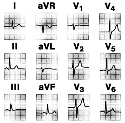
Figure 1.1. 12-lead ECG. (Reproduced with permission from the American Heart Association.1)
Normal sinus rhythm ranges between 60 and 100 beats per minute (bpm). Sinus node depolarization is not recorded on the surface ECG (Figure 1.2). Activation of the atrial myocardium produces P waves on the surface ECG. Right atrial activation is represented on the initial part of the P wave, whereas the terminal part represents left atrial activation. The impulse then travels through the atrioventricular (AV) node, His bundle, bundle branches, Purkinje fibers, and the myocardium. The isoelectric part of the PR interval represents activation of the impulse through the AV node, His-Purkinje, and the Purkinje system, while the QRS complex represents ventricular depolarization. Ventricular repolarization is recorded as T wave.
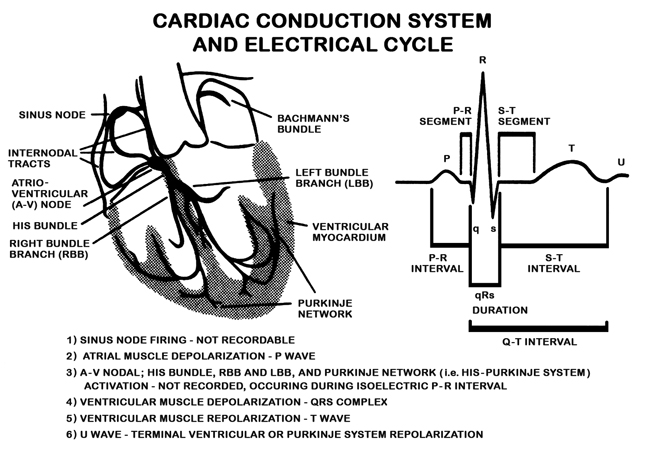
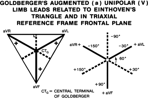
Figure 1.3. By connecting electrodes attached to the arms and the left leg, an indifferent central terminal at a zero potential can be obtained (Figure 1.3). An exploring electrode can then be applied to the extremities to obtain local electrical potentials. In clinical electrocardiography, such unipolar limb leads can be obtained by attaching pacing electrodes to the right arm (VR), left arm (VL), and the left leg (VF). On a triaxial frame system, connecting the apices of the Einthoven’s triangle with the center of the equilateral triangle can project VR, VL, and VF. Unipolar leads generally register lower voltages than bipolar leads and thus need a correction factor. (Reproduced with permission from the American Heart Association.1)
Augmented unipolar leads related to Einthoven’s triangle are depicted in Figure 1.3. Goldberger created modified unipolar leads by removing resistors from the central terminal and designating them aVR, aVL, and aVF. On a circular scale, the positive ends of aVL, aVR, and aVF can be projected as –30, –150, and +90 degrees, respectively. By producing the leads on negative halves, all 6 limb leads can be obtained on a hexaxial reference frame system. Figure 1.4
Stay updated, free articles. Join our Telegram channel

Full access? Get Clinical Tree


