FIGURE 29.1. Preoperative varicose vein map report.
In patients presenting with groin, medial thigh, and upper posterior thigh varicose veins, a pelvic source from an incompetent internal iliac vein branch should be considered (Fig. 29.2). This varicose vein pattern is almost invariably seen only in female patients, and it is most often present during or after pregnancy. It is common in these cases that the terminal valve of the GSV is competent, and the GSV becomes incompetent when a varicose vein branch from the pelvic veins empties into it. When performing a varicose vein study, if the GSV is incompetent and yet the terminal valve is competent, an alternative source for the reflux should be investigated such as a perforator vein, a pelvic branch, or a branch from an incompetent accessory vein.
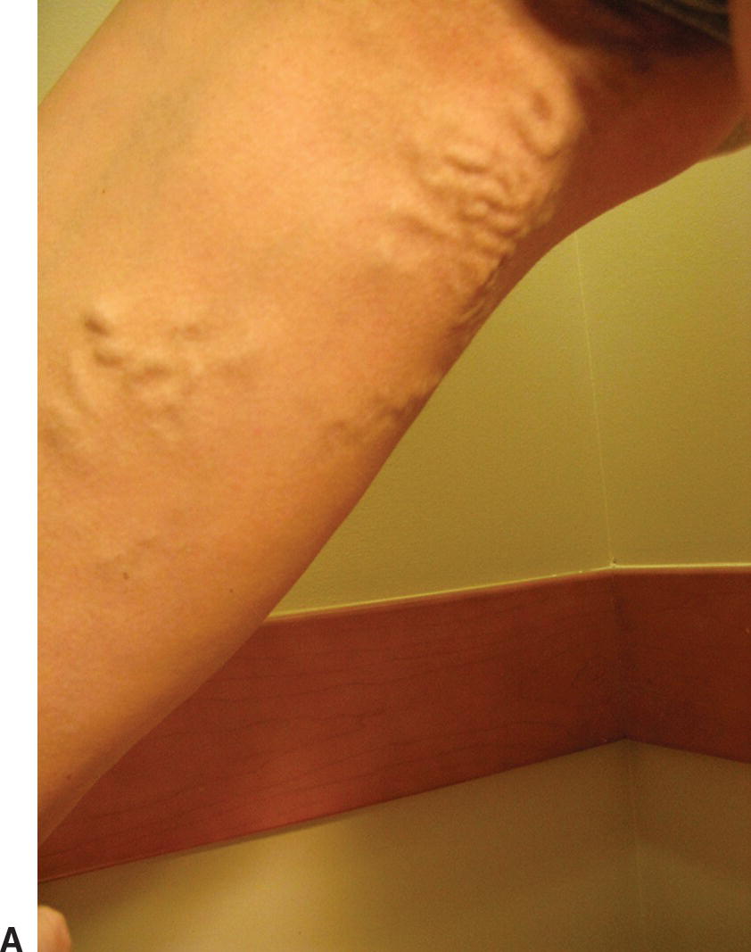
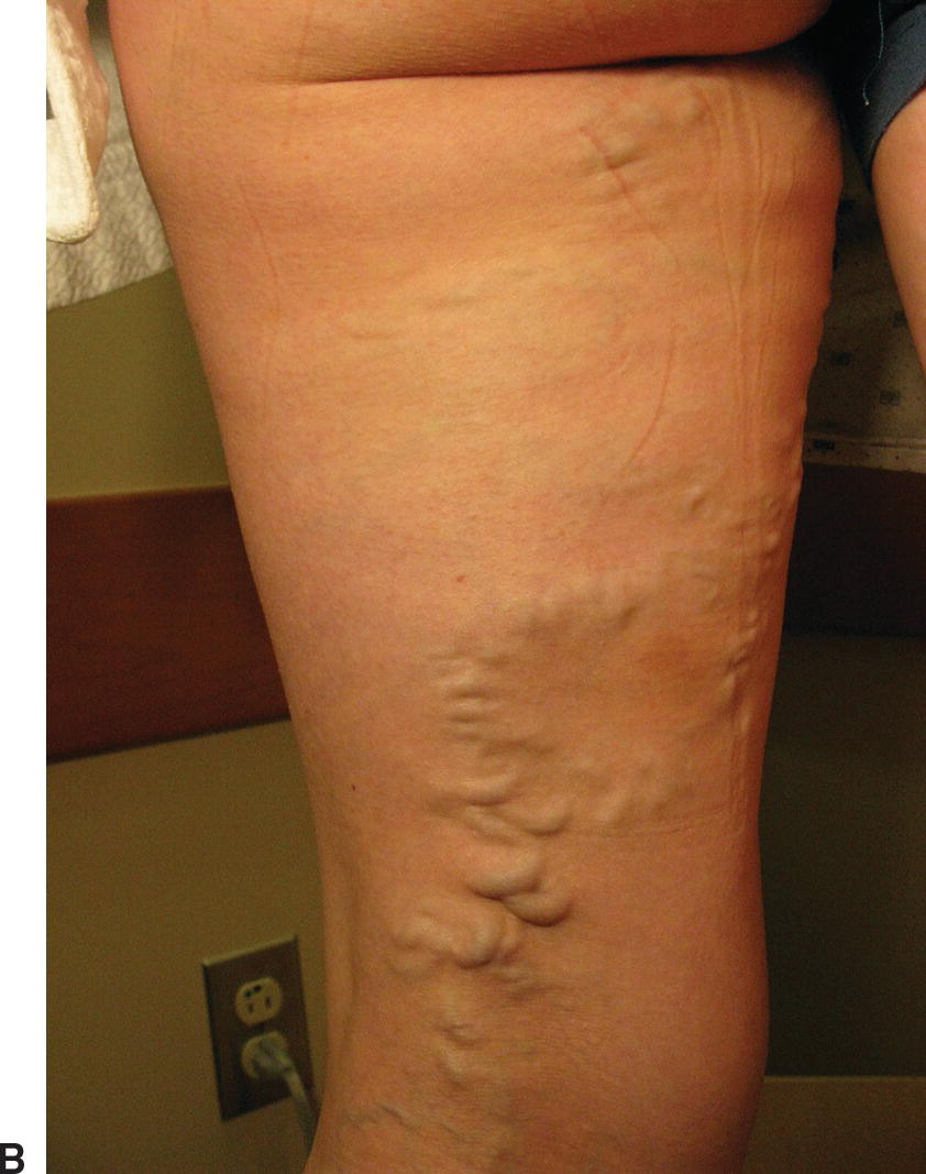
FIGURE 29.2. A, B, Nonsaphenous sources of varicose veins. A pelvic source of reflux should be considered in patients presenting with groin, medial thigh, or upper posterior thigh varicose veins.
Precise near-field resolution is the most important feature for diagnostic imaging and treatment of varicose veins. In our practice, we use a GE Logic 9 machine with a 12-MHz “hockey stick” probe and a 10-MHz linear probe for preoperative mapping. Documentation of deep and superficial venous incompetence, as well as the presence of any clinically significant refluxing perforator veins, is noted.
TREATMENT
After the surgeon is provided with a report and a detailed vein map, a treatment plan can be made. Endovenous ablation techniques can be used to treat the GSV, SSV, accessory branches, and even perforator veins. An incompetent anterolateral branch from the saphenofemoral junction (SFJ) is a common cause of lateral thigh and calf varicosities, with the varicosities often terminating in an incompetent lateral calf perforator. Depending on the distribution and size of side branches, adjunctive treatments such as microphlebectomy, perforator ligation, and UGFS can be considered and performed at the same time as the EVLT or RF procedure.
The importance of good duplex imaging in ensuring the safety and efficacy of endovenous techniques cannot be overstated. Each step of the procedure from initial access of the vein to adequate tumescent anesthesia to proper placement of the laser or RF catheter requires accurate imaging. In many practices, the treating physician holds the ultrasound probe with one hand and accesses the vein with the other, and a vascular technologist is either not involved or simply adjusts the controls on the ultrasound machine. Our team includes a registered vascular technologist (RVT) who holds the probe and plays an integral role in the procedure. We find this two-person approach increases the speed and efficiency of the procedure, and we also find it to be less ergonomically fatiguing for the surgeon. This team approach has been very rewarding in our practice, increasing collegiality between the RVT and physician, as well as improving the diagnostic skills of our vascular technologists. Being an active member of the treatment team helps the vascular technologist to think “like a surgeon” during venous examinations—anticipating what information will be needed for successful treatment of the venous abnormalities.
Scanning Technique
Many practices use compact or laptop-sized duplex ultrasound machines for endovenous ablation. We have found the near-field resolution of these machines to be suboptimal, particularly in the performance of UGFS, and we use the same machine for treatment as we do for preoperative veins mapping. To perform endovenous ablation, the patient is positioned supine for the GSV and either prone or supine for the SSV. A quick prescan is performed to ensure that there has been no change since the varicose vein mapping study. The vascular technologist scans through the saphenous trunks, identifies perforator veins and potential difficulties, and finds a good target site for cannulation. The limb is then prepped and draped in a sterile fashion.
Venous Access and Catheter Placement
Cannulation of the vein—obtaining needle and wire access—is the most critical step to a successful procedure. Venopuncture with failed wire access inevitably causes venospasm. If this occurs, a more proximal access site must be used, although occasionally a more distal access site will also work, as long as the introducer wire can traverse the area of spasm. The desired venous access site is identified by ultrasound imaging after prepping, and access can be accomplished using either a cross-sectional or longitudinal view. In our practice, we usually access the vein initially in cross section, and then switch to a longitudinal view for wire placement (Fig. 29.3). There may be multiple cannulation sites depending on how many venous segments need to be ablated.
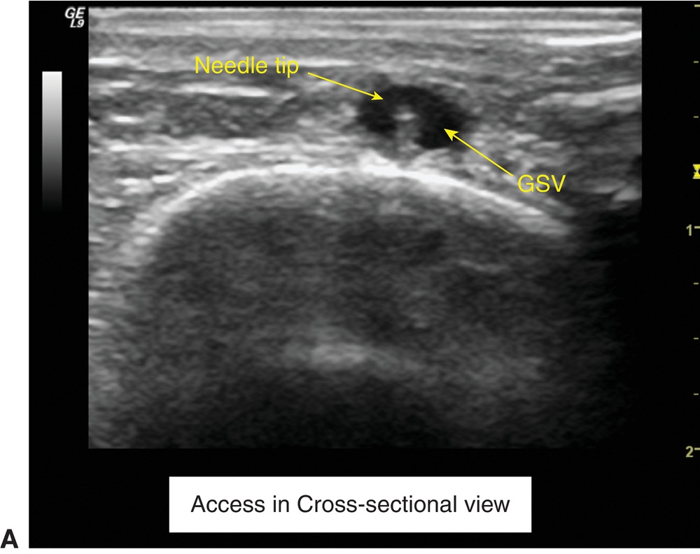
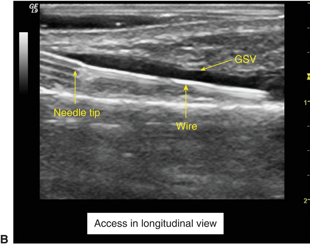
FIGURE 29.3. Vein cannulation in cross-sectional (A) and longitudinal views (B). (GSV, great saphenous vein).
The probe is positioned directly over the vein lumen, centered in a cross-sectional view, providing a clear image of the vein lumen for the physician. Depth and gain are adjusted for maximal visualization of the target vein. A wheal of local anesthetic is placed in the dermis superficial to the vein to be accessed. Access is gained with a micropuncture kit (19 g reflective tip access needle, 0.018” short wire, and 4-Fr microsheath) for EVLT and with a proprietary access kit for an RF procedure, while visualizing the target vein with the 12-MHz “hockey stick” probe. The excellent near-field resolution of this probe makes access of even relatively small veins possible. Once the physician sees a “flash” of blood in the micropuncture needle, indicating that the vein has been cannulated, the probe is lifted (carefully, so as not to disturb the needle and puncture site) and turned to provide a longitudinal plane image. This view allows the physician to see the wire enter the lumen clearly. If there is blood return but the wire will not pass, it is possible that the needle may not have entered the lumen fully or the needle could have punctured through the lumen and is “back walled.” The longitudinal view provides the best image for confirmation of wire placement, and often one can salvage a back-walled puncture with slow needle withdrawal using this view.
The sheath size for EVLT is 4 French (1.33 mm), and sheath size for RF is 7 French (2.3 mm). In practice, access of veins less than 2.0 mm in diameter is very difficult, and accessing veins greater than 3.0 mm in diameter is straightforward if using a 4 French sheath. If the veins are seen on imaging to be in spasm, and are smaller than they had been on the preoperative mapping, access may be difficult. Placing the patient in reverse Trendelenburg position, warming the limb with sterile towels, using a bed warmer, and sedating the patient can often enlarge the veins to a size that is accessible. Some practices use topical nitroglycerine to induce vasodilation and improve ease of access.
With laser ablation, after access with a micropuncture needle, a micropuncture sheath is advanced and proper placement is confirmed. A 0.035-mm wire is then passed into the desired position. The vascular technologist scans over the vein from the puncture site to the desired end point to ensure that the wire is coursing through the target vein and not entering the deep system through a perforator vein. The wire should be visualized to cross the SFJ into the common femoral vein for the GSV (unless there has been previous SFJ ligation) or through the saphenopopliteal junction (SPJ) for the SSV (if there is a connection between the SSV and the popliteal vein). A long sheath that has been flushed with heparinized saline is then passed over the wire, the wire is removed, and a laser fiber placed through the sheath. For RF ablation, the catheter is generally placed through the short 7 French sheath and passed directly to the SFJ or SPJ with direct ultrasound visualization. If the target vein is tortuous or has dilated segments that “catch” the edge of the catheter, a 0.025 or smaller guidewire may be used to facilitate RF catheter placement.
The tip of the laser fiber or RF catheter should be positioned back at least 2.0 to 2.5 cm from the SFJ or SPJ. If a superficial epigastric or external pudendal vein or a competent thigh extension branch vein are present at the SFJ or SPJ, we recommend positioning the device tip distal (i.e., caudal) to these branches to keep them open (Fig. 29.4). Proper positioning may keep the junction patent and make thrombus extension into deep veins less likely. In our practice, the RVT and the surgeon must both agree that the tip is adequately distal (caudal) to the SFJ or SPJ before proceeding. Attention to leg position is important, since a fiber or catheter entering the GSV below the knee and positioned 2 cm caudal to the SFJ while the knee is in extension may easily protrude into the common femoral vein during knee flexion done to facilitate tumescent injections. Failure to appreciate and recognize this movement of the device tip could lead to injury of the common femoral vein with permanent serious consequences. The quality of ultrasound imaging and the expertise of the vascular technologist are of paramount importance in ensuring the safety of endovenous procedures.
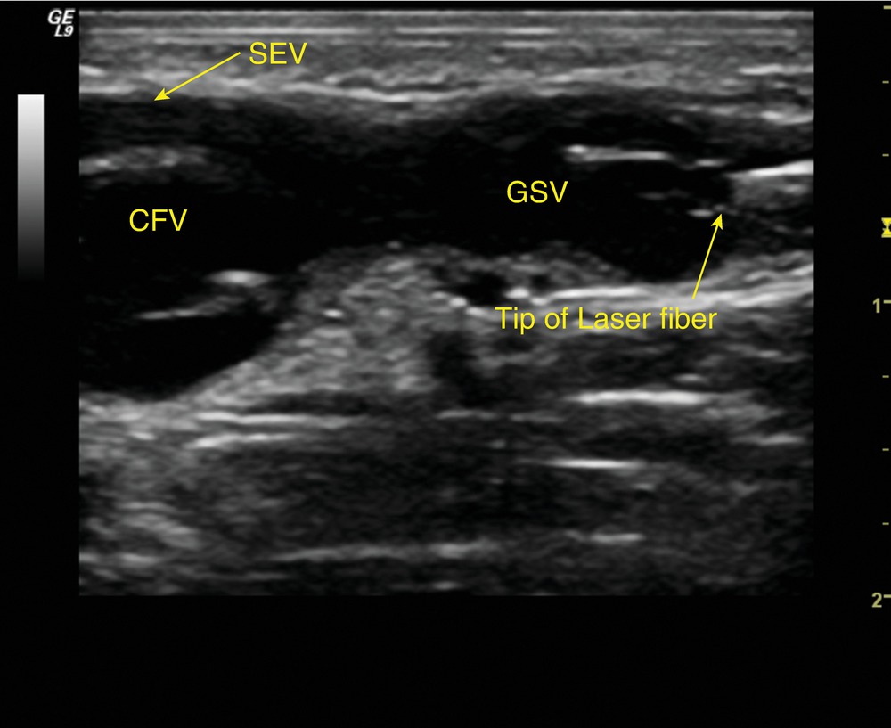
FIGURE 29.4. Position of a laser fiber tip distal to the superficial epigastric vein (SEV). (CFV, common femoral vein; GSV, great saphenous vein).
Tumescent Anesthesia
Tumescent anesthesia—the injection of a saline and local anesthetic solution around the vein to be treated—is the next step in the procedure. Tumescent anesthesia has four purposes:
1. It helps to push blood out of the vein and collapse the vein wall onto the laser or RF catheter, thus preventing a layer of blood from “protecting” the vein wall from the intentional thermal injury.
2. It pushes the surrounding tissue away from the vein, including saphenous or sural nerve fibers.
3. The local anesthetic numbs the tissue surrounding the vein.
4. It provides a “heat sink” around the vein to dilute and dissipate the heat from the endothermal energy. The layer of tumescent solution should “push” the vein down so that it is at least 1 cm below the surface of the skin.
Ultrasound imaging guides the tumescence injection and ensures that an adequate “collar” of solution surrounds the vein. A micropuncture or spinal needle is used to inject the solution just above and parallel to the sheath to create a layer of tumescence surrounding the sheath and laser or RF catheter. The tumescence lifts the fascia away from the vein creating a visible wedge of fluid above the vein (Fig. 29.5). The ultrasound probe is generally held in a longitudinal view during injection of tumescence, and a cross-sectional view will verify adequate tumescence around a collapsed vein. Placement of the probe directly perpendicular to the saphenous vein is essential to successful tumescence. This allows the surgeon to “come in” directly over the vein, with the tumescent needle in full view in the ultrasound image. This also ensures that the tumescent fluid is distributed evenly around the vein lumen and compresses all sides. If the vein is under a fascial layer, the cross-sectional view of the laser or RF catheter and sheath within the vein after tumescence should look like an “eye” (Fig. 29.6).
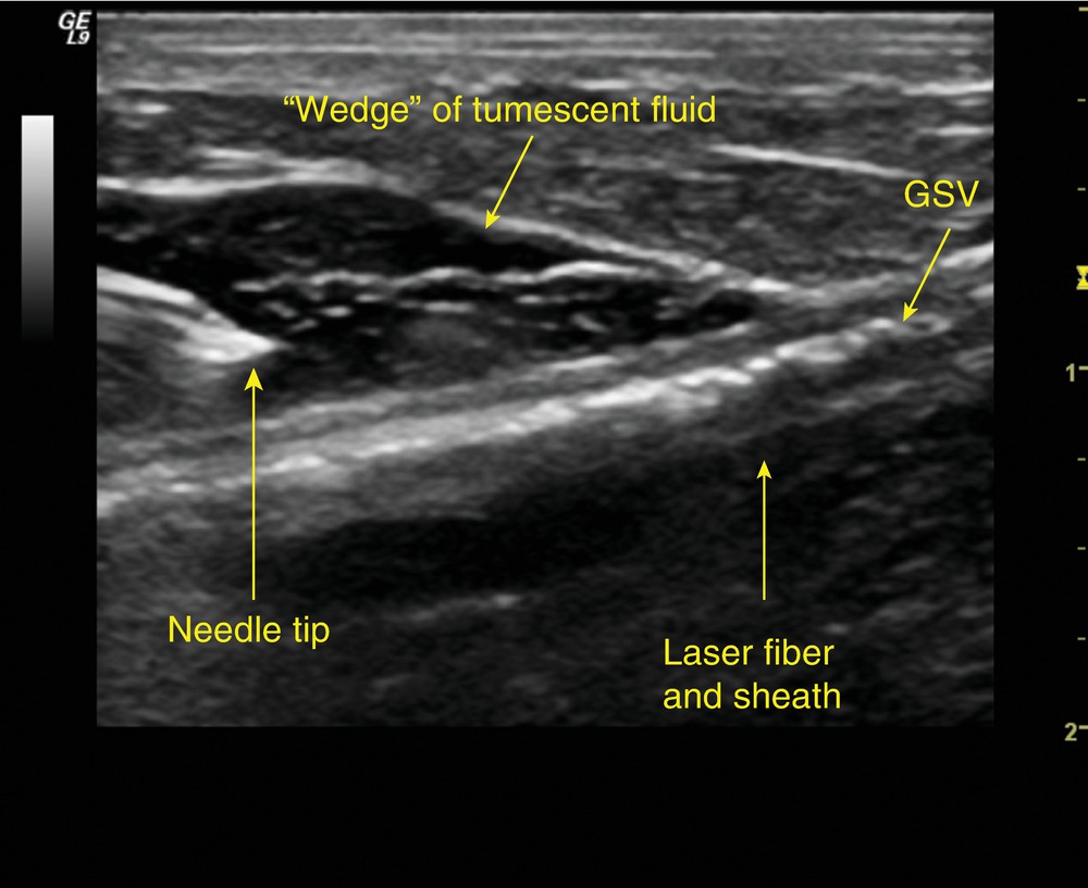
FIGURE 29.5. Tumescent fluid surrounding the great saphenous vein (GSV) and sheath with laser fiber in longitudinal view.
Stay updated, free articles. Join our Telegram channel

Full access? Get Clinical Tree


