Michael A. Bettmann
The Chest Radiograph in Cardiovascular Disease
The chest x-ray (CXR) remains the most common radiographic examination and one of the most difficult to interpret. With careful evaluation, it yields a large amount of anatomic and physiologic information, but it is difficult and sometimes even impossible to extract all the information that it contains. The aims of this chapter are to review how the CXR is obtained, present a basic approach to its interpretation, and discuss and illustrate common and characteristic CXR findings in adults with cardiovascular disease. The major variables that determine what can be learned from the CXR include (1) the technical factors (milliamperage, kilovoltage, exposure duration) used in obtaining the CXR; (2) patient-specific factors (e.g., body habitus, age, physiologic status, ability to stand and to take and hold a deep breath); and (3) the training, experience, and focus of the interpreter.
Technical Considerations
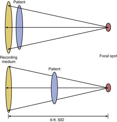
The usual CXR study consists of a frontal view and a lateral view: a posteroanterior (PA) view of the patient while standing with the chest toward the recording medium and back to the x-ray tube and a lateral view of the patient while standing with the left side toward the film. For both views, the x-ray tube is positioned at a distance of 6 feet from the film, a 6-foot source-image distance (SID). The rationale for these conventions is based on physics; x-rays are created by inducing a high current across a diode, thereby generating electrons aimed at a metal target, the anode. When the electrons reach the target, x-ray photons are produced. The anode is made of special metals, rotates at high speed, and is housed in an oil-filled container, all to preserve the target and to ensure that production of the photons is uniform in number and energy without damage to the anode. The anode has an angled edge so that the x-rays emerge at essentially a right angle to the incoming electron beam. The x-rays are allowed to emerge from the tube housing only through a small opening, the focal spot. The smaller the focal spot, the higher the energy required to deliver a given number of photons. Also, the smaller the focal spot, the narrower the x-ray beam (i.e., the closer to a true point source), thus leading to improved imaging geometry. The ability of the x-rays to penetrate structures is determined by the combination of kilovoltage, milliamperage, and duration of exposure. These factors are also the major (but not sole) determinants of the radiation dose to the patient.1,2
In theory, x-rays emerge from the x-ray tube as a point source, remain parallel, and do not diverge from each other, and consequently there is no geometric distortion of structures as they pass through the body and are recorded on film. In reality, however, the x-rays form a cone-shaped beam. They diverge from the focal spot and become less parallel as the distance from the focal spot (i.e., SID) increases. When the incident x-rays interact with film or a digital screen, there is geometric distortion as a function of the distance from the midline of the x-ray beam and the distance of the structures from the film. If one imagines a wide-diameter structure, such as the thorax, that is perpendicular to the center of the x-ray beam, the farther from the tube that the object is, the more parallel the x-rays that penetrate it (Figs. 15-1 and 15-2). Conversely, the closer the object and film to the x-ray tube, the more the incident x-rays must diverge to cover the edges of the object. Thus the farther an object is from the source, the less geometric distortion that is encountered. The greater the distance from the source, however, the more energy that must be applied to penetrate the object to be imaged and to expose the x-ray recording medium. That is, in simple terms, resolution is improved by increasing the SID, but tube energy and therefore exposure to the patient must also be increased as the SID increases. To balance these opposing concerns, a standard convention has been developed; routine standing CXRs are obtained with an SID of 6 feet.
X-rays are blocked from the film or other recording medium to varying degrees by various structures, which leads to shades of gray that allow discrimination between the heart, which is fluid filled and relatively impervious to x-rays, and the air-filled lung parenchyma, which blocks few x-rays. The exposure that the patient receives is a function of the strength and duration of the current applied to the x-ray tube (or more precisely and accurately, a function of the number, strength, and duration of the x-ray photons produced—milliamperage, kilovoltage, and milliseconds), size of the focal spot, distance from the tube to the patient, and degree to which the x-rays are blocked and scattered within the patient. Most patient exposure is not a result of the x-rays that penetrate but rather those that interact with body structures and are slowed and changed and, in the process, deposit residual energy in tissue. This process is what is broadly referred to as scatter. As the amount of tissue that attenuates photons increases, the amount of energy deposition within the patient will increase. Patients who are very thin will require an inherently lower x-ray dose to achieve diagnostically satisfactory deposition of x-ray photons on an imaging medium and will have less deposition of energy within the body. In patients who are obese, a higher x-ray dose will be necessary to penetrate the patient and produce a diagnostic exposure. The increased soft tissue in these patients also causes more dispersion of the x-ray beam and results in a higher dose. Scatter not only leads to deposition of energy in the patient but also deposits energy in surrounding structures, including personnel, if they are close to the patient (as with fluoroscopy), and the recording medium. That is, the film or digital plate is altered not only by the incident x-rays intended to produce the image (i.e., signal) but also by scatter, which does not reflect anatomic structures but will detract from the resolution of these structures (i.e., noise). The more scatter deposited on the recording medium, the more the image quality is denigrated and the worse the resolution—the signal-to-noise ratio is decreased. This is why the resolution of CXRs is worse in larger than in thinner patients when all other factors remain constant.
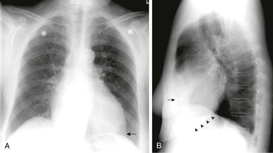
Several additional practical considerations are related to the physics of CXRs. The standard CXR is obtained with deep inspiration and the patient facing the film. If patients are unable to stand, CXRs are generally obtained with the patient’s chest toward the tube and back toward the film, the anteroposterior (AP) position. With the standard PA view, the heart appears smaller and its size and contour are more accurately depicted than on an AP view because the SID is larger and the heart is closer to the recording medium. With AP views, as with portable films, there is a resultant greater divergence of the x-rays because the heart lies relatively anteriorly (and thus is farther from the film) and the SID is short. Similarly, on a standard lateral film, the right ribs appear larger than the left ribs (Fig. 15-2B). In both cases this effect occurs because a structure is farther from the film. As a result there is increased divergence of the x-rays from the midline point source and relative magnification. Therefore the side of an effusion can generally be delineated on a lateral radiograph by determining whether the effusion is associated with the side on which the ribs appear larger or the side on which they appear smaller (see Fig. 15-2B).
Portable CXRs have inherent practical limitations. Most are obtained with patients positioned supine or semisupine. Depth of inspiration is therefore likely to be decreased in comparison to an erect film, which makes the heart appear relatively larger and provides less optimal visualization of the lungs because they are not optimally expanded. Furthermore, portable radiographs are invariably taken as AP views and the SID is less than 6 feet, for obvious practical reasons, including space constraints and the limited power of portable x-ray machines, which require longer exposure time and consequently are subject to increased cardiac and respiratory motion and decreased resolution. Inherently, then, resolution is poorer with portable radiographs, thus making them less accurate and useful. In addition, the radiation dose to both patients and personnel is generally greater.
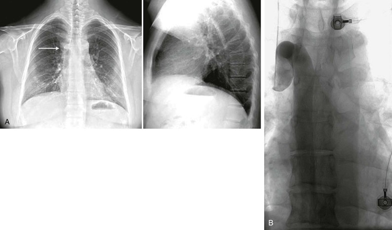
Portable CXRs are most useful for answering relatively simple mechanical questions, such as whether a pacemaker or implantable cardioverter-defibrillator (ICD) is properly positioned (Fig. e15-1 ), whether an endotracheal tube is in the correct location, and whether the mediastinum is midline.2–4 They are not generally good at providing physiologic or complex anatomic information, and there are questions that cannot be answered accurately from a portable CXR. If the CXR is obtained with the patient in less than an upright position, it is impossible to exclude even a sizable pneumothorax or pleural effusion. Because of the patient’s position, shorter SID, and limited tube output, it is impossible to accurately evaluate heart size and contour or status of the pulmonary vasculature. Although portable CXRs may be convenient and provide some information, they should be performed only in limited situations when clearly needed to answer specific questions.3,4
Image Recording and Radiation Exposure
Until the turn of the last century, all CXRs were recorded on high-resolution radiographic film. With optimal technique and a cooperative patient who can hold a deep inspiration, the result is a study that clearly and accurately depicts very small structures, such as the contour of small pulmonary arteries. With radiographic film, the incident x-rays (and scattered photons) alter the silver iodide crystals in an emulsion. When the film is developed, these alterations produce an image reflecting the extent to which the x-rays have interacted with specific areas of the film. There is inherently very high resolution of structures because of the small size of the silver iodide crystals and their sensitivity to incident x-ray photons. This has changed with the use of computed radiography (CR) and digital radiography (DR), filmless forms of radiography. DR is the direct recording of images by digital means, without analog-to-digital conversion, onto a panel that allows direct recording of incident photons of different energy and frequency on a flat digital panel, without the use of a permanent film or analog-to-digital conversion. This information is then directly downloaded and can be viewed and postprocessed. CR is similar, but instead of a direct connection to the radiology information system (RIS), the image is recorded onto a reusable panel, which is then “read” into the system and downloaded. Currently, CR is less expensive, and because it does not inherently require direct connection to the RIS, it is widely used for portable imaging. As the cost of flat panels for DR decreases and the ability to download images wirelessly improves, CR is gradually being replaced. The inherent resolution with both is very similar to that of conventional radiographic film, but the elimination of analog-to-digital conversion eliminates some noise and thus the overall resolution tends to be as good as with conventional film-screen radiographs.5–16 DR has additional advantages. First, digital technology leads to an image that is posted immediately on the RIS, without going through the step of developing the film. Using picture archiving and communication systems (PACS), digital images are then available as soon as they are downloaded for review at any location where a PACS-enabled workstation is present. This adds speed and availability and obviates the problem of lost films—all films are digitally archived—and the need to go to a remote location to review a film.17,18 The dose to an individual patient may or may not be lower as a function of patient factors and the specific imaging system.8,15,17 Overall radiation exposure to patients, however, is decreased because the need to repeat films as a result of inadequate positioning or exposure is substantially eliminated: with DR, the image can be postprocessed to alter the relative density (window and level), and magnification and even the area included can be altered without re-exposing the patient. This provides the ability to add substantial information (Fig. e15-2 ). Storage of conventional radiographic films is relatively straightforward, although it is time and space intensive. Storage of digital images, even though initially more complex, eliminates many of the major problems encountered with storage of standard radiographs. Integration with a system-wide electronic medical record allows improved access and use in comparison to what was available even a decade ago.17,18

The radiation exposure to the patient should always be kept in mind when any radiographic study is ordered or performed. The complexity of diagnostic radiation in the general population limits obtaining clear answers. The radiation necessary for PA and lateral CXRs is usually minimal in terms of radiation effects, in both the dose of a single study (generally <1 mSv) and the cumulative dose of repeated CXRs. In pregnant women and children, radiation exposure is always a concern because of the long latency period for radiation-induced cancer.19–21 Concerns have been raised that exposure of the population has increased over the last few decades, largely because of the use of high-tech imaging such as computed tomography (CT), radionuclide studies, and cardiac interventional procedures. The contribution from conventional imaging procedures such as CXRs is small, but the precise relationships between individual exposures and cumulative effect are not known. Basically, all diagnostic imaging carries at least a small theoretical risk, even at very low doses, so any use must balance this possible risk against the probable benefit; each CXR should be ordered with care.2,3,20
Normal Chest Radiograph
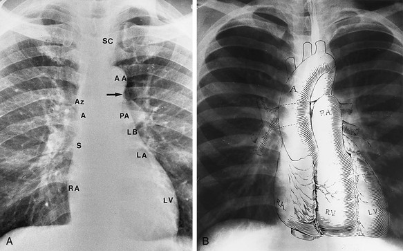
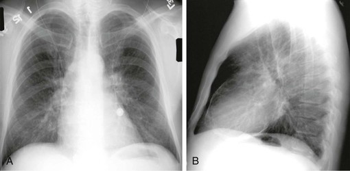
Interpreting standard PA and lateral CXRs is a daunting task. The amount of information present is huge, and there are countless relevant variables that must be evaluated: the soft tissues, bones and joints, pleura, lungs and major airways, pulmonary vasculature, mediastinum and its contents, heart (and specifically its chambers), the aorta, and areas below the diaphragm and above the thorax. It is imperative to take a systematic and standardized approach, based first on assessment of the anatomy, then the physiology, and finally the pathology. Any approach must be based on an understanding of what is normal.22,23 On the standard PA CXR, the overall heart diameter is normally less than half the transverse diameter of the thorax (Fig. 15-3). The heart overlies the thoracic spine, roughly 75% to the left and 25% to the right of the spine. The mediastinum is narrow superiorly, and normally the descending aorta can be defined from the arch to the dome of the diaphragm on the left. The pulmonary hila are seen below the aortic arch, slightly higher on the left than on the right. On the lateral CXR (Fig. 15-4), the left main pulmonary artery can be seen coursing superiorly and posteriorly relative to the right. On both frontal and lateral views, the ascending aorta (aortic root) is normally obscured by the main pulmonary artery and both atria. The location of the pulmonary outflow tract is usually clear on the lateral film.
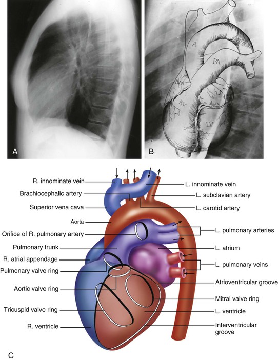
Cardiac Chambers and Aorta
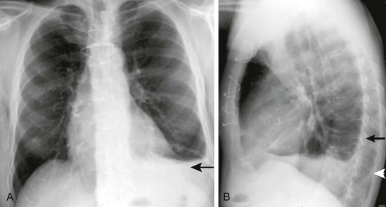
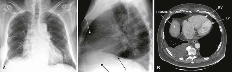
On a normal CXR it is not usually possible to define individual cardiac chambers. It is imperative, however, to know their normal position and to determine whether the size and location of each chamber and the great vessels are within the normal range. On the PA view, the right contour of the mediastinum contains the right atrium and the ascending aorta and superior vena cava (SVC). If the azygous vein is enlarged secondary to right-sided heart failure or SVC obstruction (Fig. e15-3 ), it may also be visible. The right ventricle, as is clear from cross-sectional imaging (Fig. 15-5), is located partially overlying the left ventricle on both frontal and lateral views.24 The left atrium is located just inferior to the left pulmonary hilum. Individuals with normal anatomy have a concavity at this level, the location of the left atrial (LA) appendage. The atrium constitutes the upper portion of the posterior contour of the heart on the lateral CXR but cannot normally be separated from the left ventricle. The left ventricle constitutes the prominent, rounded apex of the heart on the frontal view and the sloping inferior portion of the mediastinum on the lateral view (see Figs. 15-3 and 15-4).
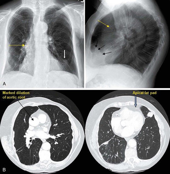
The apex is often not clearly delineated for a reason related to x-ray attenuation. The heart is distinguishable from the lungs because it contains water-density blood rather than air. Because blood attenuates x-rays to a greater extent than air does, the heart appears relatively white (although less so than calcium-containing bones) and the lungs relatively black (less so than the edges of the CXR, where there is only air and no interposed tissue). A fat pad of varying thickness surrounds the apex of the heart (Figs. 15-6 and e15-4 ). Fat has a density greater than that of air and marginally less than that of blood. As it covers the ventricular apex, the fat pad is relatively thick and dense. As it thins out toward the left lateral chest wall, it is progressively less dense, which explains the hazy, poorly marginated appearance of the apex. Similarly, a fat pad may be seen on the lateral CXR as a wedge-shaped density overlying the anterior aspect of the left ventricle (see Figs. 15-6 and e15-4). The pericardial sac cannot normally be defined (Fig. 15-7). The borders of the cardiac silhouette are normally moderately but not completely sharp in contour. Even though the exposure time for a CXR is very short (<100 milliseconds), normal cardiac motion is usually sufficient to cause minor haziness of the silhouette. If a portion of the heart border does not move (as with a left ventricular [LV] aneurysm) the border may be unusually sharp (Fig. e15-5
 ). The aortic arch is generally visible because the aorta courses posteriorly and is surrounded by air. Most of the descending aorta is also visible. The position and the size of each can easily be evaluated (see Figs. 15-6 and e15-2) on the frontal and lateral views.
Stay updated, free articles. Join our Telegram channel

Full access? Get Clinical Tree


