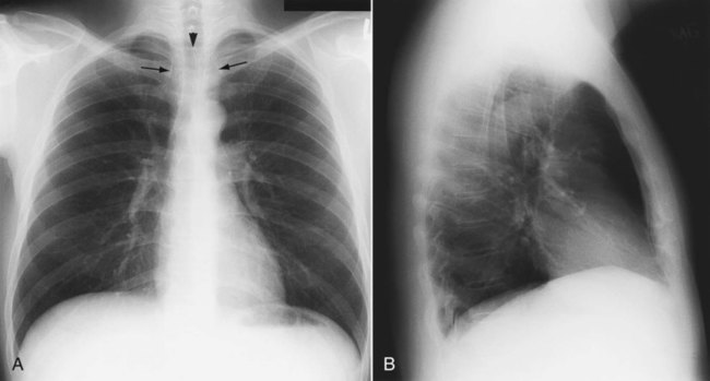
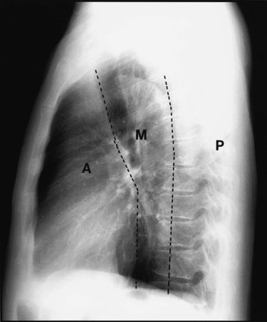
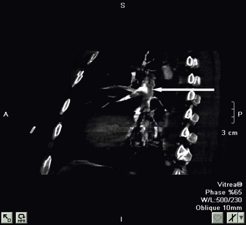
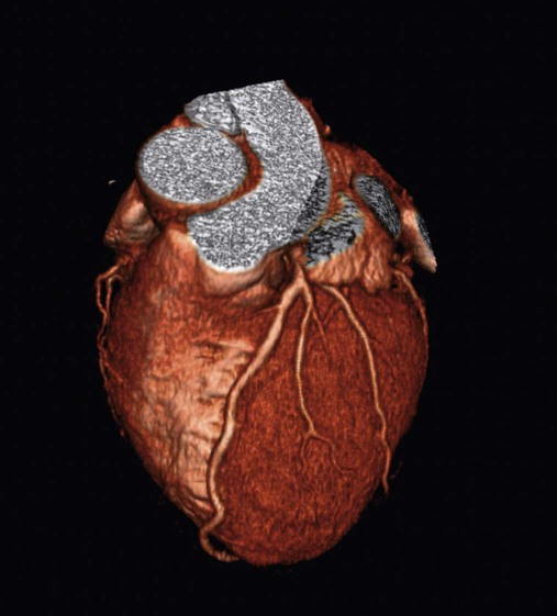
Review of Thoracic Imaging


Review of Thoracic Imaging


N. Lennard Specht and James K. Stoller


Chest imaging is crucial in the practice of pulmonary and critical care medicine. It is essential that the respiratory therapist (RT) have a solid understanding of chest imaging to facilitate patient assessment. Various chest imaging modes exist, including conventional chest film (more accurately called a radiograph or roentgenogram after Roentgen, who first discovered the x-ray beam), computed tomography (CT) scanning, ultrasound, and magnetic resonance imaging (MRI).


Scanning radioactive material within a patient after inhalation or injection of a radioisotope is a separate radiographic technique. Radioisotopes are used for ventilation/perfusion (image) scans, which have been historically used in the diagnosis of pulmonary embolism. Radioisotope injections are also used for positron emission tomography (PET), which may help localize tumors and metastases. The branch of medicine that uses radioisotopes to generate images is often called nuclear medicine.


This chapter summarizes important concepts in chest imaging for the RT. The basic elements of plain chest radiography are addressed first, and then the role of various imaging techniques used to evaluate the different components of the chest (e.g., pleura, mediastinum, lung tissue [parenchyma]) is described. Examples of abnormal findings are shown, including some images obtained with the more sophisticated techniques such as ultrasound, CT, and MRI.


Overview of Plain Chest Radiograph


Passing an x-ray beam through part of a person’s body to a photographic film creates an x-ray film. The resulting image is formed as x-rays strike the film and darken it. A radiograph is similar to a negative from an old-fashioned black and white film camera. X-rays that pass directly through low-density tissue (e.g., lung) strike the film more directly and cause the resulting shadow to turn darker. X-rays that strike denser tissue (e.g., bone) are more absorbed and leave the exposed film lighter. The shadows on the radiograph vary in shades of gray based on the density of the tissue through which the x-ray beam has passed.


Four different tissue densities are visible on a normal chest radiograph. The tissue types that generate these densities are air, fat, soft tissue (water density because soft tissues, similar to muscle, are mainly composed of water), and bone. Each tissue absorbs different amounts of the x-ray beam, which varies the shade of the shadow on the final film. Air in the lung, stomach, or intestines absorbs the least energy and appears virtually black on a film (radiolucent). Soft tissue absorbs a small amount of the x-ray beam and is usually seen as a medium gray shadow. Bone absorbs a large amount of the x-ray beam and is seen as a nearly white (radiopaque) shadow. Fat absorbs a slightly smaller amount of x-ray energy than soft tissue and appears just slightly darker than soft tissue.


X-ray images have traditionally been recorded on film. Once developed, x-ray films can be displayed by placing the film over a viewbox that illuminates the film for the observer. At the present time, most x-ray films are recorded and displayed in a digital format. To record a digital image, an x-ray detector (digital film) replaces the photographic film. A computer takes the data from the x-ray detector and creates the image. The resulting image is projected on a computer monitor.


Compared with images recorded on traditional film, digital images have advantages regarding the interpretation of the image and its retrieval. The display of digital images can be manipulated by adjusting contrast, brightness, and magnification. These adjustments allow findings that would be subtle and hard to see on traditional film to be seen more easily. Digital images also allow multiple people to see the image at the same time on large plasma screen viewing stations or multiple people in different locations to see the image. For example, an RT in a critical care unit, a radiologist in the imaging department, and a critical care physician in another hospital may collaborate by all viewing at the same time an x-ray image on a rapidly deteriorating patient. Digital images can also be easily copied and recorded on compact discs so that patients can get digital copies of films to take to their physicians. One can easily imagine a time when such images will be kept by individuals on their own digital files of medical information or transmitted from one facility to another as patients move or travel.


The structures visible on a chest radiograph are seen only when tissue of one density is next to tissue of another density. The heart is visible as a soft tissue density in the middle of the chest because the lungs, which are primarily air density, normally surround it. If the chest on either side of the heart were filled with water (pulmonary consolidation or pleural effusion), the normal heart shadow would be invisible on the radiograph. This obscuring of the margin of adjacent structures of the same density is called the silhouette sign and can be useful to localize abnormalities within the lung anatomically.


When to obtain a chest radiograph is ultimately the decision of the attending physician. However, the RT may be able to suggest that a chest x-ray should be obtained in certain circumstances, such as when a patient in the intensive care unit suddenly deteriorates for no apparent reason. The RT needs to be familiar with the common clinical indications for obtaining a chest radiograph (Box 20-1).


A chest radiograph is extremely valuable in many patients with lung disease, but it does have limitations. A chest radiograph may appear normal even though the patient is in respiratory failure; this is common in patients with acute (e.g., pulmonary embolism) or chronic obstructive lung disease (e.g., emphysema that is not apparent on a plain chest x-ray). In addition, the chest radiograph may lag behind the clinical condition of the patient. This situation is common in pneumonia, where the patient may present with high fever and cough typical for pneumonia, but an infiltrate may not appear on a chest film until 12 to 24 hours later. Similarly, the infiltrate on the chest film may persist for days to weeks after symptoms of pneumonia have resolved.


Approach to Reading a Plain Chest Radiograph


A disciplined approach is required to obtain the maximal value out of any diagnostic imaging study. A plain chest radiograph may best exemplify this statement. An obvious abnormality such as a 6-cm mass is easily spotted, even by the untrained eye. Such an abnormality tends to monopolize the observer’s attention immediately, which causes more subtle abnormalities, often with equal or even greater diagnostic importance, to go unnoticed. To avoid this pitfall, the observer must develop a step-by-step approach that is applied to reading a plain chest x-ray in a disciplined fashion until it becomes second nature. The following suggestions are broad guidelines, and each observer must formulate an approach that he or she finds comfortable.


In broad terms, the steps in reviewing a chest film are as follows:


In subsequent sections, to discuss common abnormalities that the RT should recognize, the following areas are reviewed: (1) evaluation of the technical quality and adequacy of the film, (2) normal anatomic structures on a chest radiograph, (3) more sophisticated imaging techniques, and (4) major anatomic components seen on the radiograph.


Chest Radiograph Technique and Quality


Several technical factors should be routinely assessed when reading a chest film:


As the first step, the RT should check the patient’s identity on the film or image file and all labels visible on the film. This check helps avoid the mistake of interpreting a chest radiograph for a patient different than the patient being considered and establishes which side is which because labels are often placed to indicate the patient’s left or right side; such labeling of the side is important in cases where the patient’s chest or abdominal contents are reversed—known as situs inversus or dextrocardia.


Mini Clini


Evaluating the Heart Size on a Portable Chest Radiograph


A standard chest film is obtained with the patient standing and facing the film cassette. The x-ray beam penetrates the patient’s back first and then passes through the anterior chest and finally to the film. This standard technique is called the posteroanterior (PA) chest film. The heart is located very close to the film with the standard PA view, and magnification of the heart shadow is minimal.


A plain chest radiograph is taken using one of two techniques: the PA view or the AP view. The views are named for the path of the x-ray beam. In the PA view, the patient puts his or her back to the x-ray source and the chest against the film. The x-ray beam leaves the source, passes through the posterior (P) side of the patient, through the patient and then through the patient’s anterior (A) surface, and finally to the film. The PA view is usually performed in the radiology department with equipment that standardizes the distance from the x-ray source to the film and where the x-ray technician can maximize the quality of each film. In addition, as noted, taking the film with the anterior chest closest to the film minimizes magnification of the heart.


The AP film is usually taken with a portable x-ray machine. The AP technique puts the x-ray source in front of the patient with the film behind the patient’s back. The source of the x-ray beam is usually much closer to the patient than with a PA film, although the distance varies from patient to patient. The closer x-ray source and the position of the patient both lead to a slight magnification of the heart shadow. The AP film is usually taken in the intensive care unit because these patients are too ill to go out of the intensive care unit to the radiology department. Overall, AP portable films are usually of lesser quality compared with PA films. During the reading of the chest radiograph, the RT needs to take into account the view (AP or PA) as he or she interprets the heart size and subtle findings that may be influenced by film quality and technique.


When a chest film is taken using the portable AP technique, it is sometimes difficult to align the patient properly, and a portion of the chest may be missed. Although these problems are seen far more often with portable films, they may occur with PA and lateral films as well. The RT should ask the following questions: (1) Is the whole chest visible on the film? (2) Is the patient well positioned?


Patient rotation can make interpretation more difficult by projecting midline structures (e.g., the trachea) to the right or left. The observer can assess for rotation by comparing anterior structures such as the medial (toward the middle) ends of the clavicles with a posterior structure such as the spinous process (midline structure of the spine). In a perfectly positioned or aligned chest film, the spinous process should be seen midway between the medial ends of the clavicles and in the middle of the tracheal air column (Figure 20-1). Patient rotation makes the mediastinum appear unusually wide and obscures or distorts the appearance of the pulmonary arteries as they emerge from the mediastinum into the lung parenchyma.


The RT also must ensure that the film is adequately penetrated. An improperly penetrated film may conceal important details. A chest radiograph with proper exposure should show the intervertebral disc spaces through the shadow of the heart and should allow the blood vessels in the peripheral regions of the lungs to be visualized. A chest radiograph that is underexposed or underpenetrated (i.e., owing to too-low kilovoltage of the x-ray beam) does not allow visualization of the intervertebral discs through the heart shadow and may make identification of pathology in soft tissue areas such as the mediastinum more difficult. Specifically, an underpenetrated film may cause the normal branching of the pulmonary arteries in the lung to appear abnormal and be misinterpreted as evidence of interstitial infiltrates. Similarly, an overpenetrated radiograph overexposes the film, leaving the lung parenchyma black and no ability to visualize the peripheral blood vessels or abnormalities that may be present (e.g., infiltrates secondary to pneumonia, pulmonary nodules). This overpenetration makes evaluation of the lung parenchyma far more difficult. Adjustment of the contrast and brightness of the chest film on the computer display improves the ability to see certain aspects of a chest x-ray with improper penetration. However, adjusting the display cannot completely overcome the loss of important details caused by an improperly penetrated film.


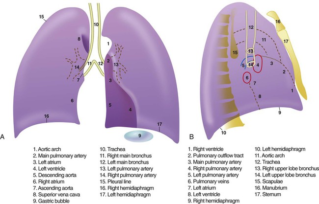
Anatomic Structures Seen on a Chest Radiograph


After the RT has reviewed the technical aspects of the chest radiograph, it is time to review the anatomic findings in the film. The main structures imaged on a routine chest radiograph are listed next and illustrated in Figure 20-2:


1. Bones (e.g., ribs, clavicles, scapulae, vertebrae)


2. Soft tissues (e.g., tissues of the chest wall, upper abdomen, lymph nodes)


3. Lungs (including the trachea, bronchi, and lung tissue or parenchyma)


4. Pleura (membranous coverings of the lung, including the visceral pleura [the part attached to the lungs] and the parietal pleura [the part lining the inside of the chest wall]; although normally occupied by only a small amount of fluid, the space between the parietal and visceral pleura is called the pleural space)


5. Heart, great vessels, and mediastinum (i.e., the tissues between the two lungs in the center of the chest, bordered by the sternum and the vertebral column in the AP dimension and by the thoracic inlet [where the trachea enters the thorax] and the diaphragm in the cephalocaudal direction)


6. Upper abdomen


7. Lower neck


The anatomy seen on the film should be reviewed in a thorough, systematic manner. All of the above-listed anatomic structures must be individually assessed. When first beginning to read films, it is helpful for the RT to create a list of the anatomic structures that must be assessed and to check off the structures as they are reviewed. As the reader gains experience, the checklist becomes second nature and automatic.


Assessment of the chest wall should include looking for symmetry, rib fractures, or other bone changes. Lung evaluation begins by assessing the size and density. Any obvious differences in symmetry must be explained. Of the lung parenchyma, 80% to 90% is overlaid with bone in the form of ribs, clavicles, and spine. The overlying bone may conceal some lung abnormalities. A lateral film is helpful in clarifying the presence or absence of suspicious lung abnormalities on frontal projections. The RT must pay specific attention to areas where subtle abnormalities may be hiding; these include the lung tissue behind the clavicles (especially medially), the area of lung that projects behind the heart, and part of the lung that lies deep in the posterior sulcus (the extreme bottom of the lung projecting behind the dome of the diaphragm on the frontal view).


Review of the lung edge on both frontal and lateral films discloses any pleural abnormalities, such as fluid in the pleural space (e.g., hydrothorax, hemothorax [blood in the pleural space]) and air in the pleural space (pneumothorax). Evaluation of the mediastinum should include assessment of heart size. In the PA projection, the diameter of the heart shadow should not exceed one-half the diameter of the chest. An enlarged heart may occur with congestive heart failure or with a large pericardial effusion (accumulation of fluid within the space that surrounds the heart encased within the pericardium). The lateral contours of the mediastinum should correspond to normal anatomic structures as outlined in Figure 20-3.


Advanced Chest Imaging Techniques


Computed Tomography of the Chest


Computed tomography (CT) scanning is a very helpful chest imaging technique because it can visualize structures in cross section and can visualize great detail and miniscule structures (e.g., approximately 2 mm) within the lungs. To perform a CT scan, a patient lies on an examination table called a gantry. The gantry is passed into a circular opening in the CT scanner. X-ray sources and detectors surround the opening in the scanner. When the scanning begins, the x-ray source and detectors pass quickly around the patient in a circular motion with the x-ray beam passing through the patient to the detector on the opposite side. The information from the detector is sent to a computer, which calculates the two-dimensional image from the data sent to it. The image created by the scan looks like a slice of the patient. Originally after each CT image was made, the gantry and patient were advanced 1 cm for the next image. The scanning and stepwise advancement of the patient were repeated until the entire chest was imaged.


Newer CT scanners use many x-ray sources and detectors, all connected to a highly capable image processing computer. These new CT scanners allow the patient and the examination table to pass through the scanner rapidly without stopping for each image. The term spiral or helical is often applied to these high-powered CT scanners, which can gather complete images in seconds.


Conventional CT scanning provides an excellent view of the chest and allows imaging of portions of the chest that are poorly seen on plain chest radiographs. Areas such as the mediastinum, the apices and costophrenic sulci of the lungs (the normally sharp shadows where the diaphragm contacts the rib cage laterally), and the pleural surfaces all are easily seen with CT scanning. Injection of iodinated contrast material makes blood appear denser (radiopaque or white) and allows blood vessels to be distinguished from soft tissue structures such as lymph nodes, further enhancing the ability to evaluate areas such as the mediastinum. Conventional CT scanning of the chest is commonly performed to evaluate the following: lung nodules and masses, great vessels of the chest, mediastinum, and pleural disease.


Conventional CT scans display images as slices every 3 to 7 mm. Each slice displays everything within the 3- to 7-mm slice of tissue. CT scans can also evaluate the delicate structures of lung parenchyma. To see lung parenchyma optimally, images need to be displayed with extremely thin slices, often 1 mm thick or less. To limit the number of images to be reviewed, thin-slice CT scans often provide images at intervals of 5 mm or 10 mm. When displayed this way, thin-cut CT scan images provide great detail of lung parenchyma but just a sampling of lung tissue rather than displaying the entire chest. The term high-resolution CT scanning (HRCT) is associated with CT scans designed to evaluate the lung parenchyma using thin-slice images. High-quality CT scanners often acquire much more image data than are displayed. Image data can be easily formatted into either conventional or thin-slice (HRCT) format. If the original image data are saved, a radiologist can easily go back and generate thin-slice images even if the CT scan was first displayed as a “conventional” CT scan. Thin-slice displays are especially helpful in imaging small nodules or the details of parenchymal infiltrates (e.g., interstitial lung disease) because such thin slices allow maximal spatial resolution (i.e., the ability to separate objects that are close together).


Computed Tomography Angiography


The rapid scanning that can be performed on helical CT scanners has made CT angiography possible. To perform CT angiography, a large amount of contrast dye is injected into the patient’s vein. The CT technician monitors the movement of contrast material so the scan can be started when the contrast material has entered the area to be studied. CT angiography of the chest has been used for years to identify pulmonary thromboemboli (Figure 20-4).1 More recently, CT angiography of the coronary artery has been evaluated; this seems to provide an alternative to routine coronary angiography in many patients.


Magnetic Resonance Imaging of the Chest


MRI is occasionally useful in evaluating chest pathology. When a patient is placed into a strong magnetic field, a portion of the nuclei of their atoms with nonzero spin numbers (nuclei that have an odd number of protons and neutrons), such as the hydrogen atom, align themselves with the magnetic field. Because hydrogen atoms are present in so many molecules in the body, they provide an excellent target for MRI evaluation. Hydrogen is in water, sugars, fats, and amino acids. A brief pulse of a radio wave causes the alignment of hydrogen nuclei to flip 180 degrees. After the radio signal is stopped, the nuclei flip back to their original alignment and release their own radio wave. MRI uses the radio waves from the realigning nuclei to generate an image. The strength of the released radio waves is typically measured at less than 100 msec (T2) and 1 second (T1) after the radio signal is stopped.

Stay updated, free articles. Join our Telegram channel

Jun 12, 2016 | Posted by in RESPIRATORY | Comments Off on Review of Thoracic Imaging

Full access? Get Clinical Tree

Get Clinical Tree app for offline access