Radiographic Evaluation of the Lungs and Chest
Jack Twersky
For the physician interested in diseases of the chest, chest radiography is of paramount importance in detecting a disease process and providing clues as to the etiology.
Routine Examination
Two views of the thorax are needed to provide a three-dimensional view of the chest: posteroanterior (PA) and lateral projections.
High-kilovoltage technique is now generally accepted practice. This technique involves the use of x-rays at the 129-kV (peak) range with a fine-line grid, which increases the information on the radiograph by providing less contrast but more penetration. Information about the mediastinum and retrocardiac areas is increased compared with films taken at a lower kilovoltage. This high-kilovoltage technique decreases exposure time and minimizes motion. Ideally, chest films should be obtained on a dedicated chest radiographic unit, allowing for the best and most consistent technique.
If the high-kilovoltage technique for standard films is not available, a grid radiograph with higher kilovoltage, higher milliamperage, or both and a fixed or moving grid allows better visualization of the mediastinum and lesions behind the heart and diaphragm. This technique, however, is not optimal for imaging of the pulmonary parenchyma (Fig. 9-1) and must therefore be considered a supplementary view.
The lateral radiograph is of considerable importance in the routine examination of the chest because some lesions in this area are apparent only in the lateral view. Examples include small mediastinal lesions, some masses in the anteromedial portions of the lung adjacent to the mediastinum (Fig. 9-2), lesions in the vertebral column, lesions behind the heart and diaphragm on the PA view, and small pleural effusions. For routine screening films in the absence of apparent chest disease, Sagel and associates (23) found that a lateral view may not be indicated because the yield of information is low. However, lesions may be easier to recognize on a lateral film and, in retrospect, may be visible on the frontal projection.
Supplementary Radiographic Views
Occasionally, other views may be added to the PA and lateral examination to confirm the parenchymal origin of a lesion. These include shallow (5-degree) oblique views. In the shallow oblique projections, the patient is rotated slightly, about 5 degrees to the right and left. The slight change in position of the patient between the two films allows separation of overlapping structures that have produced a confluence of shadows or pseudo- nodule, whereas a parenchymal nodule is seen in both positions (Fig. 9-3). Similar additional views may be obtained in the lateral position. Of course, computed tomography (CT) can clarify whether a nodule is seen. However, if CT is not readily available
or if expense is a consideration, the oblique technique may be useful.
or if expense is a consideration, the oblique technique may be useful.
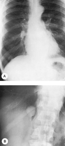 Figure 9-1. Pulmonary granuloma. A. The routine PA radiograph at a low-kilovoltage technique appears normal. B. An overpenetrated grid radiograph demonstrates a pulmonary nodule in the right lung seen through the right hemidiaphragm. |
It is helpful, in examining oblique radiographs, to remember that posteriorly placed lesions in the lung maintain a constant relationship with the spine, and anteriorly placed lesions in the lung maintain a constant relationship with the heart.
Figure 9-4 demonstrates some of the normal anatomic structures seen on the oblique radiograph. Note that these are not shallow obliques. The apical lordotic view is based on the same principles as the shallow oblique views: a change in position separates overlapping structures. This view is used in evaluating the pulmonary apices, in which lesions may be obscured by overlying ribs and clavicles in the PA projection. In the lordotic view, anteriorly placed lesions appear to move upward, and those located posteriorly move downward (Fig. 9-5). A full chest lordotic view demonstrates middle lobe collapse or consolidation if a lateral film is not obtainable.
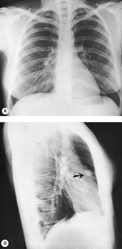 Figure 9-2. Carcinoma of the lung. A. The PA radiograph demonstrates a subtle increase in density at the inferior portion of the right hilum that would probably be unobserved without the lateral film. B. The lateral view demonstrates an obvious retrosternal abnormality (arrow). The mass was in the right upper lobe and was a primary lung cancer. |
Lateral decubitus radiographs are extremely important in the investigation of suspected pleural effusion or of air–fluid levels in pulmonary or pleural cavities. The decubitus radiograph is made with the x-ray beam projected in a horizontal plane and the patient lying on his or her side. In a left lateral decubitus view, the patient lies on his or her left side, and free pleural fluid forms a layer along the left lateral chest wall (Fig. 9-6). Amounts of fluid as small as 50 to 100 mL can be identified in the lateral decubitus position. If a pneumothorax is present and the examination is being made to investigate the air-outlined pleura, the x-ray beam should be centered on the elevated rather than the recumbent side of the patient. If effusion and
pneumothorax—hydropneumothorax—are present, an air–fluid level is seen on the lateral decubitus projection.
pneumothorax—hydropneumothorax—are present, an air–fluid level is seen on the lateral decubitus projection.
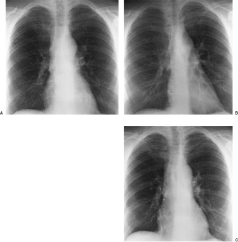 Figure 9-3. PA (A) and shallow oblique (B,C) views. A nodule was questioned behind the right anterior second rib and in the fourth to fifth intercostal space posteriorly. On oblique views, no nodule is appreciated. |
It is critical to remember that a fluid level, and particularly an air–fluid level, is not visible unless the beam is in a horizontal projection, regardless of the patient’s position; the beam must be tangential to the fluid or air–fluid interface. With the patient in a supine position with a vertical beam or in a semierect position with a nonhorizontal beam, the air–fluid level is not visualized (Figs. 9-7 and 9-8). Lateral decubitus views are useful also when air trapping is suspected, usually when an inhaled endobronchial foreign body is suspected. Normally, the dependent lung decreases in size (see Fig. 9-6). With bronchial obstruction, the obstructed lung fails to decrease in size when placed in the dependent or down-side position (Fig. 9-9). Both decubitus views are helpful for comparison if available. In small children, the decubitus views are the easiest way to evaluate for possible foreign-body aspiration and pneumothorax.
A supine radiograph is made when the patient is unable to sit or stand and is the routine projection for infants. Intensive care unit radiology is done primarily with patients in the supine position. Limitations of imaging imposed by the medical conditions of the patients, as well as the portable imaging modality, require meticulous technique. Tocino27 noted that a supine position is preferred to the semierect position for reproducibility of
technique from day to day. When possible, all foreign objects that are superimposed on the patient should be removed to avoid confusion. Milne18 cautioned that the interpretation of the supine radiograph should take into consideration the magnification of the cardiomediastinal structures as a result of the anteroposterior projection. The supine position also results in engorgement of mediastinal veins, producing mediastinal widening and increasing the upper lobe pulmonary vessels. This should not be confused with the vascular engorgement of congestive failure.
technique from day to day. When possible, all foreign objects that are superimposed on the patient should be removed to avoid confusion. Milne18 cautioned that the interpretation of the supine radiograph should take into consideration the magnification of the cardiomediastinal structures as a result of the anteroposterior projection. The supine position also results in engorgement of mediastinal veins, producing mediastinal widening and increasing the upper lobe pulmonary vessels. This should not be confused with the vascular engorgement of congestive failure.
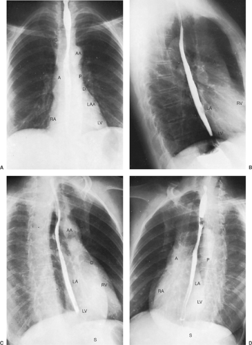 Figure 9-4. Normal PA (A), lateral (B), right anterior oblique (C), and left anterior oblique (D) radiographs. A, ascending aorta; AA, aortic arch; D, descending aorta; LA, left atrium; LAA, left atrial appendage; LV, left ventricle; P, main pulmonary artery; RA, right atrium; RV, right ventricle; S, stomach; SVC, superior vena cava. Barium is in the esophagus. |
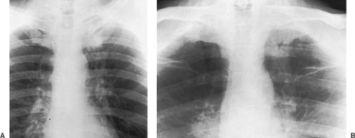 Figure 9-5. Carcinoma of the lung. A subtle increase in density is seen to the left anterior first rib in comparison with the right, which raises suspicion of a mass on the PA radiograph (A). An apical lordotic view (B) demonstrates a definite mass in the left apex below the left first rib. Note asymmetry when compared with the right apex. |
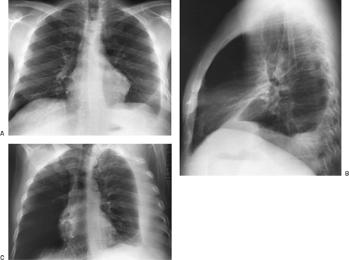 Figure 9-6. Pleural effusion. PA (A) and lateral (B) views demonstrate blunting of the left costophrenic angle. Left lateral decubitus view (C) demonstrates a large layering pleural effusion against the left chest wall. Note on the posteroanterior view (A) the increased distance between gastric bubble and left hemidiaphragm (compare with Fig. 9-2A), indicating a subpulmonic component of the pleural fluid. |
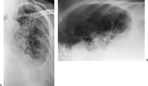 Figure 9-7. Pyopneumothorax. A. No air–fluid level is seen on the PA supine view. B. Left lateral decubitus radiograph with horizontal projection of the x-ray beam shows multiple air–fluid levels (arrowheads) consistent with unsuspected empyema and pneumo- thorax. |
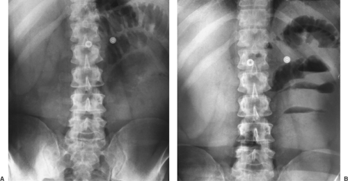 Figure 9-8. Air–fluid levels. A. Supine abdomen demonstrates a few dilated loops of bowel in the left upper quadrant. B. With the erect position and a horizontal beam, multiple air–fluid levels are identified, indicating small bowel obstruction. |
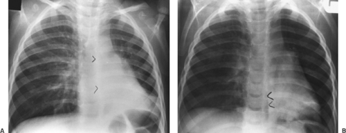 Figure 9-9. Obstructed right mainstem bronchus from inhaled peanut. A. Erect PA radiograph demonstrates signs of air trapping with shift of the mediastinum and the azygoesophageal (AE) recess to the left (arrowheads). B. A right lateral decubitus view shows no collapse of right lung and persistent shift to the left (arrowheads), indicating airway obstruction (compare with Fig. 9-6). |
An expiratory chest radiograph may also be helpful in assessing pulmonary air trapping, either local or diffuse. A foreign body or a tumor in a bronchus may create a ball-valve mechanism, allowing air to enter the lung but preventing egress of air. This is because bronchi dilate on inspiration and narrow on expiration. Air exits the normal lung, which decreases in size on expiration, but it is trapped in the obstructed lung. On the expiratory radiograph, therefore, the mediastinum shifts to the side opposite the foreign body or obstructed bronchus.
Both pleural effusions and pneumothoraces distribute differently in the thorax when the patient is in a supine position, as demonstrated by Tocino and Westcott.28 Added lucency may be seen anteromedially and laterally above the hemidiaphragms with a supine pneumothorax. The anterolateral location of a pneumothorax results in asymmetric costophrenic angles (deep sulcus sign) (Fig. 9-10). Pleural air may also be seen beneath the lung in a subpulmonic location (Fig. 9-11). In the supine position, pleural effusions may redistribute from the costophrenic angles to the apices of the thorax (Fig. 9-12). If the presence of a pneumothorax is suspected but not obvious, a lateral decubitus film should be done with attention to the up side.
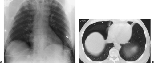 Figure 9-10. Pneumothorax on supine films. A. The right costophrenic angle is deeper and more lucent than the left as a result of anterior location of pleural air in the supine position. B. CT scan confirms location anteriorly (arrows). |
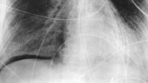 Figure 9-11. Subpulmonic pneumothorax on supine film. Intrapleural air outlines base of right lung. |
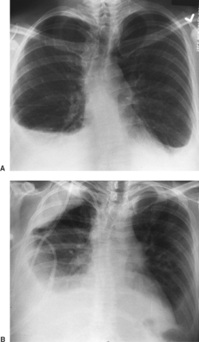 Figure 9-12. Pleural effusion on erect (A) and supine (B) films. Fluid layers over right apex from the right costophrenic angle when patient is supine. |
Digital Radiography
Digital radiography was initially used for portable images, particularly those in the intensive care unit, as noted in Seminars in Roentgenology, edited by one of the authors, and in articles by Freedman, Hartman10, and Freedman and Artz.7 It is a technique in which storage systems other than film are used to record the radiographic image. The most widely used is the photostimulable phosphor plate storage system. The plate is similar to the cassette in a film screen system. When the phosphor plate is radiated, energy is stored by raising the energy level in the electrons to higher levels proportional to the incident x-ray beam, thus forming a “latent image.” The exposed plate must then be “processed” by a mechanical-optical reader. The phosphor plate is scanned with laser light, visible light is emitted, and the analog signal is converted to a digital signal for further analysis, which eventually results in an image. As Ravin and Chotas21 noted, digital image receptors have a wide range of sensitivity and a linear response to radiation over that range. The detected image is therefore less dependent on the exposure level. This decreases the need for repeat radiography.
Digital detector systems have now become commonplace in the clinical environment in conjunction with the implementation of picture archiving and communication systems (PACSs). The acquisition, archiving, processing, and transmission of digital images has had a major impact on the practice of radiology and on availability to clinicians of the radiographic images. There are many advantages of digital storage of images versus film-based storage. First and foremost, images cannot be lost. Retrieval of prior images is rapid. Image processing of soft copy allows selective visualization of mediastinal tubes and catheters in one “window” and lung parenchyma in another. Schaefer and colleagues24 demonstrated improved visibility of these structures in comparison with standard film–screen combinations. This is particularly advantageous in the intensive care unit in looking for tubes and catheters. Reported turnaround time is markedly decreased, again improving patient care.
There are, however, some disadvantages. Image processing also can enhance noise. This may decrease conspicuity of low-contrast objects, such as nodules with hazy margins. Some detail is lost as compared with films done on a dedicated chest unit. In addition, patients may seem to have interstitial lung disease if edge enhancement is overused. One must allow for a learning curve in working initially with computed radiography as compared with film–screen images.
Computed Tomography
CT has changed markedly since it was introduced in the 1970s, both in improved image quality and in the development of slip-ring gantry technology that allows continuous rotation of the gantry for data acquisition. Spiral–helical CT (volumetric data acquisition) has significant advantages over conventional CT, as described by Leung.12 Multidetector CT, in which there are multiple detectors, combines high-resolution imaging with increased scanning speed. The thorax can be imaged in a single breath hold, which decreases respiratory misregistration of lesions and minimizes motion artifacts, as pointed out by
Rydberg and associates22 and by Ravenel and McAdams.20 Images may be displayed in the conventional fashion or in a multiplanar or three-dimensional mode. Nonionic contrast with increased speed of injection, efficient use of scanning time, overlapping reconstructions, and decreased reconstruction time are also significant developments, as pointed out by Zeman and colleagues.36 New applications as a result of this improved technology include CT pulmonary angiography and cardiac imaging. CT pulmonary angiography routinely demonstrates clots to the fourth-order vessels (segmental branches) and in many institutions has become the standard for evaluation of pulmonary emboli.34 Three-dimensional reconstruction, manipulation of the three-dimensional images, and cardiac gating allows evaluation of coronary artery calcification as well as coronary artery anatomy. Three-dimensional imaging may be particularly useful to the chest surgeon in evaluating the involvement of mediastinal structures, particularly of the great vessels, by malignant lymphadenopathy.
Rydberg and associates22 and by Ravenel and McAdams.20 Images may be displayed in the conventional fashion or in a multiplanar or three-dimensional mode. Nonionic contrast with increased speed of injection, efficient use of scanning time, overlapping reconstructions, and decreased reconstruction time are also significant developments, as pointed out by Zeman and colleagues.36 New applications as a result of this improved technology include CT pulmonary angiography and cardiac imaging. CT pulmonary angiography routinely demonstrates clots to the fourth-order vessels (segmental branches) and in many institutions has become the standard for evaluation of pulmonary emboli.34 Three-dimensional reconstruction, manipulation of the three-dimensional images, and cardiac gating allows evaluation of coronary artery calcification as well as coronary artery anatomy. Three-dimensional imaging may be particularly useful to the chest surgeon in evaluating the involvement of mediastinal structures, particularly of the great vessels, by malignant lymphadenopathy.
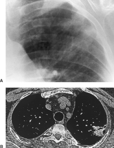 Figure 9-13. Amiodarone toxicity. A. Poorly marginated focal opacity in the left upper lobe. Patient had no pulmonary symptoms. B. On CT, opacity measures 127 Hounsfield units compatible with iodine accumulation in the lung, a sign of amiodarone toxicity. |
CT is far more sensitive in the detection of density differences: differences of 0.5% can be recognized by this technique, whereas density differences of 4% to 5% are necessary for recognition on the usual radiograph. Subtle differences in density may be accentuated by changing the scale of contrast and the center point (i.e., window width and level). An example of abnormal increase in density in the lung may be seen with amiodarone therapy. This may result in an accumulation of iodine within the pulmonary macrophages. Although the increase in density is not appreciated on a plain film, it may be seen on CT scan and indicates pulmonary toxicity (Fig. 9-13).
CT scanning is particularly useful in identifying mediastinal nodes when the routine chest radiograph is equivocal or normal. Unfortunately, size criteria for enlargement do not allow complete separation of malignant from benign lymphadenopathy. McCloud and colleagues14 noted a sensitivity of 64% and a specificity of 62% when results of CT scanning of the mediastinum in patients with lung cancer were correlated with surgical findings. This may not obviate mediastinoscopy but does provide guidelines for further surgical staging or may identify patients who are candidates for adjunct chemotherapy. In addition, CT scanning is useful in the mediastinum, where absorption characteristics of various masses may yield useful information (Fig. 9-14).
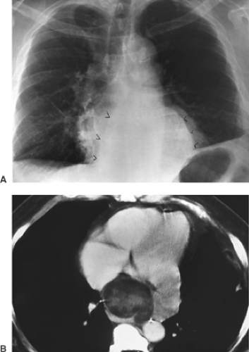 Figure 9-14. Liposarcoma of the mediastinum. A. PA chest view shows mediastinal mass (arrowheads) of indeterminate origin. B. CT demonstrates heterogeneous mass with some low densities compatible with fat. |
Magnetic Resonance Imaging
Magnetic resonance imaging (MRI) uses radio waves modified by a magnetic field to produce images that contain somewhat different information than that obtained in the standard radiograph or CT scan. Intravenous contrast is often not required. MRI in the chest is particularly useful in studying mediastinal structures. Lymph nodes are easily distinguished from mediastinal fat. The great vessels are readily imaged in a multiplanar fashion, and no contrast is required for the evaluation of thoracic aortic disease. MRI is superior to CT in imaging the brachial plexus in the case of a suspected Pancoast or apical tumor (see Chapter 11).
Fluoroscopy
Historically, fluoroscopy was used to evaluate diaphragmatic motion, mediastinal shift, and cardiac calcifications. Currently, the diagnostic use of fluoroscopy is limited to the sniff test to distinguish between diaphragmatic weakness (eventration) and paralysis. Diaphragmatic motion is observed while the patient sniffs. Paradoxical elevation of a hemidiaphragm of 2 cm or more correlates strongly with phrenic nerve paralysis. Real-time ultrasound, however, can be used for the same purpose and has the advantages of portability, lack of ionizing radiation, and direct visualization of the diaphragm. Phrenic nerve stimulation in the neck is the most definitive test to differentiate diaphragmatic neuropathy and myopathy.
Fluoroscopy is an excellent technique for transthoracic needle aspiration biopsy of pulmonary lesions if the lesion is large enough to be seen in two projections. Being able to visualize the lesion in real time is a significant advantage over CT-guided biopsy and decreases the time of the biopsy considerably. However, small lesions may not be evident in two projections on fluoroscopy, and CT guidance is needed. Real-time CT guidance systems are becoming available. This allows biopsy of small “moving” lesions adjacent to vital structures.
Lung
The anatomic positions of the lung and the normal fissures are described in Chapter 5. The interlobar septa or major fissures are frequently visible on chest radiography as thin lines (Fig. 9-15) and are of great help in assessing loss of volume in any of the lobes. Anomalous septa are not uncommon. Any pulmonary segment may have an anomalous fissure between that segment and the remainder of the lobe, resulting in an accessory lobe. The most common anomalous fissures are the superior and inferior accessory fissures. The superior accessory fissure occurs in 5% of anatomic specimens and separates the superior segment of the lower lobe from the basilar segments. The inferior accessory fissure occurs in about 30% of anatomic specimens and separates the medial basal segment of the right lower lobe from the remainder of the right lower lobe. They are, however, seen much less frequently on radiographs. A commonly seen anatomic accessory fissure is the azygos fissure, which extends
superolaterally from the azygos vein to the apex of the right lung as a comma-shaped structure with the azygos vein at its inferior end and should not be mistaken for pathology. More often than not, the fissures are incomplete. This allows collateral air drift between lobes of the lung (see Fig. 9-15).
superolaterally from the azygos vein to the apex of the right lung as a comma-shaped structure with the azygos vein at its inferior end and should not be mistaken for pathology. More often than not, the fissures are incomplete. This allows collateral air drift between lobes of the lung (see Fig. 9-15).
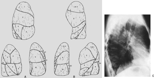 Figure 9-15. A. Topographic positions of the bronchopulmonary segments of the right lung seen in the anterior, lateral, and posterior views. B. Topographic positions of the bronchopulmonary segments of the left lung seen in the anterior, lateral, and posterior views. C. Radiograph revealing the major fissures bilaterally and minor fissure on the right. Patient had interstitial edema and fluid in the fissures. |
Each lobe of the lung is divided into several pulmonary segments, each of which is supplied by a segmental bronchus. Various names have been applied to the pulmonary subsegments. The widely used classification of Jackson and Huber11 and the numeric classification of Boyden1 are presented in Table 9-1 and are illustrated in Figure 9-15. The pulmonary segments may undergo consolidation or atelectasis. The characteristic configuration of pulmonary consolidation of the various segments is schematically presented in Figures 9-16, 9-17, 9-18, 9-19, 9-20. Occasionally, consolidation of an anomalous pulmonary segment can be recognized on routine radiography. Identification of a segmental distribution of an opacity is helpful in developing a differential diagnosis.
Table 9-1 Bronchopulmonary Segments | ||||||||||||||||||||||||||||||||||||||||||||||||||||||||||||
|---|---|---|---|---|---|---|---|---|---|---|---|---|---|---|---|---|---|---|---|---|---|---|---|---|---|---|---|---|---|---|---|---|---|---|---|---|---|---|---|---|---|---|---|---|---|---|---|---|---|---|---|---|---|---|---|---|---|---|---|---|
| ||||||||||||||||||||||||||||||||||||||||||||||||||||||||||||
The pulmonary arteries accompany the bronchial tree and exhibit a segmental distribution similar to that of the bronchial tree. The pulmonary veins are slightly larger than the arteries and lie lateral to them in the upper lobes and somewhat more horizontal in the lower lobes. More peripherally the pulmonary veins run in the interlobular septa, whereas the arteries and bronchi are distributed centrally in the pulmonary lobules. It frequently is possible to distinguish between the arteries and veins on routine radiography of the chest.
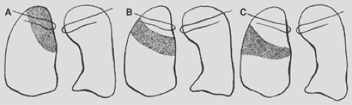 Figure 9-16. Consolidation of the right upper lobe. A. Apical segment. B. Posterior segment. C. Anterior segment. |
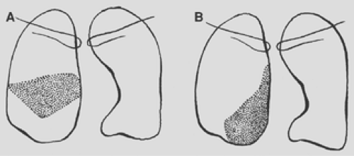 Figure 9-17. Consolidation of the right middle lobe. A. Lateral segment. B. Medial segment. |
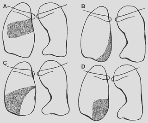 Figure 9-18. Consolidation of the right lower lobe. A. Superior segment. B. Medial basal segment. C. Lateral basal segment. D. Posterior basal segment. |
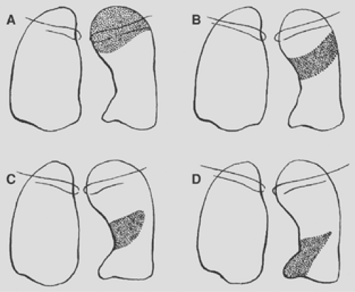 Figure 9-19. Consolidation of the left upper lobe. A. Apical posterior segment. B. Anterior segment. C. Lingular segment, superior division. D. Lingular segment, inferior division. |
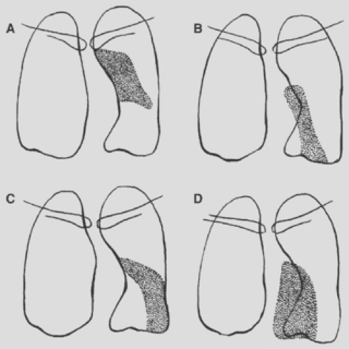 Figure 9-20. Consolidation of the left lower lobe. A. Superior segment. B. Lateral basal segment. C. Anteromedial basal segment. D. Posterior basal segment. |
Mediastinum
The heart occupies the major part of the lower half of the mediastinum anterior to the spine. On the PA radiograph, the transverse diameter of the heart is normally one half or less of the maximum transverse diameter of the chest. Detailed discussion of the anatomy and pathology of the heart is beyond the scope of this text. Figure 9-4 demonstrates the normal position of the cardiac chambers and the great vessels in the PA and lateral projections.
Stay updated, free articles. Join our Telegram channel

Full access? Get Clinical Tree


