Pulmonary Function Testing
INTRODUCTION
The assessment of human pulmonary function dates back to the seventeenth century, when the earliest measurements of tidal volume were noted. In 1800, Humphry Davy employed a hydrogen dilution technique to measure his own residual volume (RV).1 Subsequently, John Hutchinson, in his treatise, On the Capacity of the Lungs and on Respiratory Functions, defined the functional subdivisions of lung volume and reported the results of vital capacity measurements performed in more than 1800 subjects. He related these measurements to the subjects’ height, age, and weight, thereby establishing a basis for determining normal values.2,3
Progress in development of techniques for pulmonary function testing progressed slowly over the next century. However, in the 1950s, pulmonary physiologists made use of the tools provided by the evolving fields of electronics and computer science. Currently, many techniques exist for assessing both the integrated performance of the cardiovascular and respiratory systems and their individual components. This chapter focuses on commonly used tests of pulmonary function.4 Detailed assessment of integrated pulmonary and cardiovascular function is described in Chapter 34. Additional tests that have not yet been validated or are not routinely available for clinical purposes5 are not included in the discussion.
LUNG VOLUMES AND SUBDIVISIONS
Important quantitative aspects of respiratory function are the changes in lung volume with inspiration and expiration and the absolute volume of air that the lungs hold at various times during the respiratory cycle. These volumes and changes in volume are described in subsequent sections.
 DEFINITIONS AND ASSESSMENT
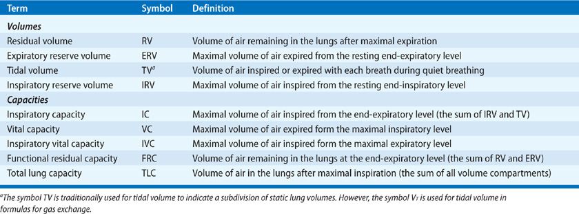
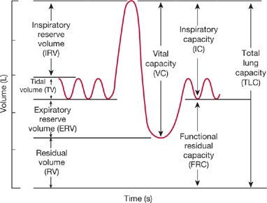
For purposes of quantification and comparison, the total volume of gas in the lungs is conventionally subdivided into compartments (volumes) and combinations of two or more volumes (capacities). For many of these subdivisions, the end-expiratory volume – the volume of gas remaining in the lungs at the end of normal expiration – is the point of reference. Lung volumes and capacities are defined in Table 33-1 and are depicted schematically in the tracing shown in Figure 33-1, which was obtained using a device called a spirometer. The relationships between the volumes recorded directly by the spirometer and the other lung volumes and capacities – including total lung capacity (TLC), functional residual capacity (FRC), RV, and inspiratory capacity (IC) – are highlighted in the figure.
Figure 33-1 The subdivisions of lung volume as recorded by a spirometer. The record is generated on paper calibrated for volume in the vertical direction and time in the horizontal. The term capacity is applied to a subdivision composed of two or more volumes. The definitions of these subdivisions are found in Table 33-1.
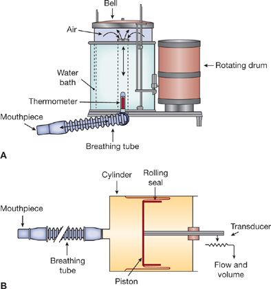
Spirometers that measure volume or change in volume versus time have been used extensively in pulmonary function laboratories. Previously, through manual calculations, or, in modern times, through application of microprocessors, the relationships among volume, flow, and time are generated to provide a measure of the respiratory system’s ability to move air. Two examples of volume-type spirometers of historical note are shown in Figure 33-2. They are discussed briefly to highlight the ingenuity behind their use in determining clinically important physiologic measurements.
Figure 33-2 Two types of spirometers: water sealed (A) and dry rolling seal (B). Movement of air through the breathing tube results in movement of the bell (A) or piston (B). The output signal is either mechanical (pen on rotating drum) or electrical (flow and volume as voltage changes). The primary design criteria for these instruments are that inertia and resistance to airflow must be held to negligible levels, and the calibration must be accurate and stable.
In the water-sealed spirometer (Fig. 33-2A), a mouthpiece is attached to a tube through which air passes into a lightweight bell that is inverted over a water bath. Air movement through the mouthpiece into the bell during expiration causes the bell to rise; conversely, as air is withdrawn from the system during inspiration, the bell falls. The change in volume with time can be recorded on a calibrated rotating drum or digitally noted by a computer and displayed on a screen in both graphic and numeric formats.
In the dry, rolling-seal spirometer (Fig. 33-2B), a cylinder with a rolling plastic seal is substituted for the spirometer bell and its water seal. Movement of air through the mouthpiece effects a change in the position of the piston, which is attached to a variable resistor. The resistor, in turn, generates voltage signals proportional to volume changes reflected in displacement of the piston. These signals are processed by a computer to generate graphic and numeric outputs similar to those of the water-sealed spirometer.
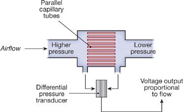
Currently, most pulmonary function laboratories utilize flow-type spirometers using pneumotachographs or rotating turbines to determine airflow. Two types of pneumotachographs are in general use: hot wire and flow resistive. In the hot-wire type, air flowing past a heated wire cools the wire, thereby altering its resistance in proportion to changes in airflow. Flow-resistive pneumotachographs contain a resistive element composed of parallel tubes (Fig. 33-3), a wire mesh, or a fibrous, paperlike element. Airflow through the resistive element results in a pressure gradient across the device, which can be measured by a very sensitive differential pressure gauge. In the model depicted in Figure 33-3, the array of parallel, small-bore tubes maintains a laminar gas flow pattern through the pneumotachograph. As a result, the pressure–flow characteristics of the system can be described by Poiseuille’s law:
![]()

Figure 33-3 Principle of pneumotachography. During unidirectional airflow, a pressure drop is created across a resistive element made up of an array of parallel capillary tubes. The magnitude of the pressure drop is related to airflow, as described by Poiseuille’s law for a laminar flow system. The pressure drop is transduced to a proportional voltage output, which can be recorded. A heating element (not shown) maintains the temperature of the expired gas near body temperature.
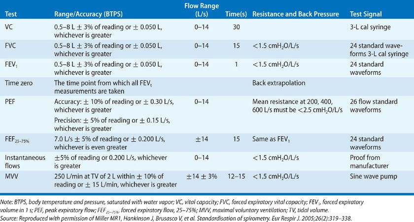
Hence, under laminar flow conditions, the flow of gas in each tube is proportional to the pressure drop across the tube. The calculation for the overall pressure drop across the entire resistive element is based on the parallel arrangement of the array of tubes. The pressure drop across the resistive element is sensed by a pressure transducer and converted to a voltage output that is proportional to flow. The flow signal can be integrated electronically to yield volume. The output signals for flow and volume are displayed on a monitor and recorded. Minimal standards have been established by the American Thoracic Society (ATS) and the European Respiratory Society (ERS) (Table 33-2) for spirometers used either for diagnostic purposes or patient monitoring.6–8
In a diagnostic setting, spirometers are used to (1) evaluate symptoms, signs, or abnormal laboratory tests; (2) measure the effect of disease on pulmonary function; (3) screen persons at risk of having pulmonary disease; (4) assess preoperative risk; (5) assess prognosis; and (6) assess health status before enrollment in strenuous physical activity programs.
On the other hand, spirometers used for patient monitoring are used to (1) assess therapeutic interventions, including bronchodilator therapy, management of congestive heart failure, etc.; (2) characterize the course of diseases affecting lung function (e.g., obstructive or interstitial lung diseases, congestive heart failure, or neuromuscular diseases); (3) track pulmonary function in persons working in occupations or receiving medications known to affect the lung; (4) evaluate large numbers of people in disability assessments; and (5) provide data as part of epidemiologic surveys.8
In general, the diagnostic spirometer is used to assess a patient’s lung function for purposes of comparison with values expected in a normal population. The monitoring spirometer, which is less expensive and more portable, is used to evaluate a patient’s performance over time and to study large numbers of people for epidemiologic or other purposes.
 THE VITAL CAPACITY AND ITS SUBDIVISIONS
Two methods of performing a vital capacity maneuver can be used: closed-circuit and open-circuit methods. In the closed-circuit method, the seated patient, with nose clip in place, breathes quietly into the apparatus. After several breaths to establish the resting end-expiratory level, which serves as a point of reference for all subsequent measurements, the patient is urged to inspire fully and then, after reaching a plateau at maximal inspiration, to expire maximally. This expiration must be performed slowly and evenly; attempts by the patient with obstructive pulmonary disease to maximize flow often reduce expiratory volumes because of dynamic compression of the airways caused by high positive pleural pressures (see Chapter 10).Figure 33-1 illustrates schematically this relaxed or “slow” vital capacity maneuver. From the record, tidal volume, inspiratory reserve volume, expiratory reserve volume (ERV), vital capacity, and IC are calculated. A similar maneuver in which the subject breathes out as rapidly and forcefully as possible after a maximal inspiration provides a measure of the forced vital capacity (FVC). Other timed measurements of expiratory airflow (e.g., the forced expiratory volume in 1 second, or FEV1) are also determined from this type of record (see Dynamic Mechanical Properties of the Respiratory System).
In the open-circuit method of determining vital capacity, the patient inspires maximally, inserts the mouthpiece, and then exhales with a slow, constant effort to the point of maximal expiration. With this technique, the resting end-expiratory position is not recorded. Thus, only the vital capacity, not its component volumes, can be measured. The open-circuit technique offers some advantages. Since the patient inspires from room air before expiring into the apparatus, concern over acquisition of infection from contaminated inspired air is minimized. In addition, the open-circuit method is generally completed in a shorter time, providing a major advantage when epidemiologic studies are being performed on large numbers of subjects.
 FUNCTIONAL RESIDUAL CAPACITY AND RESIDUAL VOLUME
One compartment of the TLC that cannot be measured by spirometry is RV, the volume of air remaining in the lungs at the end of a maximal expiration. RV is determined indirectly in three steps: (1) FRC is typically measured using one of the three techniques: closed-circuit helium, open-circuit nitrogen, or total-body plethysmograph. (2) ERV is determined spirometrically. (3) RV is calculated as the difference between FRC and ERV. In principle, it is possible to determine the RV using a dilution technique or body plethysmography after maximal expiration. In practice, however, the resting end-expiratory level is a more reproducible starting point for determining FRC than is the maximal end-expiratory level for determining RV.
Closed-Circuit Helium Method
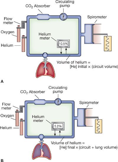
The closed-circuit helium dilution method for determining FRC is a variation of the hydrogen dilution method first used in the early 19th century. Both methods take advantage of the virtual insolubility of the test gas in body tissues and the law of conservation of mass. The development and simplification of this test were accomplished over a 20-year span in the mid-20th century. Schematic depictions of the principle upon which the technique is based and the apparatus used are shown in Figure 33-4.
Figure 33-4 Closed-circuit helium dilution method for measurement of FRC. A. Spirometer and tubing system with helium before subject begins breathing through the circuit. At the end of an expiration, the mouthpiece valve is turned and the patient rebreathes through the circuit. Expired CO2 is “scrubbed” out of the system, and O2 is added to compensate for continued O2 uptake in the lungs. B. During equilibration, the measured helium concentration falls, reflecting a dilutional effect of the additional volume (FRC) on the spirometer circuit.
When a fully manual device is used for measuring FRC, the system is prepared by the addition of about 2 L of air and sufficient helium to achieve an initial helium concentration of approximately 10% in the apparatus. The patient, with nose clip in place, then breathes room air through the mouthpiece (Fig. 33-4A). After a preliminary period of quiet breathing to familiarize the patient with the mouthpiece, apparatus, and environment, and after the baseline resting end-expiratory level is established, the test begins.
At the end of a normal expiration, the valve at the mouthpiece is turned to connect the patient to the spirometer system (Fig. 33-4B). As the patient rebreathes from the closed circuit, the blower circulates the gas mixture. The CO2 is absorbed by soda lime (CO2 absorber), while O2 is added through a valve and flowmeter at a rate corresponding to the subject’s O2 consumption. As the helium, which was at first contained entirely within the apparatus, mixes with air contained in the lungs, its concentration, as monitored by the helium analyzer, falls. Stabilization of the helium concentration, indicated by a rate of change in concentration of less than 0.02% over a 30-second interval, signals the point at which the helium concentration has equilibrated throughout the lung-breathing circuit system; equilibration, the end-point of the test, occurs within 7 minutes in normal persons. However, in patients in whom the distribution of ventilation is abnormal – for example, those with chronic obstructive pulmonary disease (COPD)– equilibration may take much longer. Upon equilibration, the following equation, based on the law of conservation of mass, is applied:


The initial volume of the system is the volume of the spirometer and circuit tubing, whereas the final volume consists of the initial volume plus FRC. The latter value is the only unknown in the preceding equation. Corrections are usually made for the small amount of helium dissolved in body tissues during the test and for slight volume changes caused by a respiratory exchange ratio that is not equal to 1.0.9 Although the method described here is based on a manually operated device, the same principles hold when all the mechanical and computational steps are accomplished with a computer-controlled system.
Nitrogen Washout Method
Conceptually, the nitrogen washout method is similar to the helium dilution method described previously; however, it relies on an open circuit rather than the closed circuit used in the helium dilution method. The open-circuit nitrogen washout method for determining FRC.10 requires that the subject breathe 100% O2 for 7 minutes; during this period, the concentration of N2 in expired gas is monitored. When the expired N2 concentration falls to zero, all the N2 present in the lungs at the start of O2 breathing has been “washed out.” The total volume of gas expired and the concentration of N2 in the expired gas are measured.
The calculation of FRC is based on the reasonable assumption that the volume of N2 in the lungs at the start of the test (i.e., the product of lung volume and the concentration of N2 in the lungs) is the same as the total volume of N2 expired and collected during the period of the test – that is, the product of the total volume of gas expired and the concentration of N2 in the expired gas:


Since the test is started at the end of a quiet expiration, the volume of gas in the lungs is FRC. This volume is calculated by substituting into the above equation the initial concentration of N2 in the lungs, estimated at 0.81 in fasting and 0.79 to 0.80 in nonfasting subjects, and the measured values for volume and N2 concentration of expired gas.
Body Plethysmography
The word plethysmography is derived from the Greek plethysmos, meaning “enlargement.” Although the concept of measuring FRC by recording changes in the volume of the body during “enlargement” of the chest was described in 1882, not until 1956 did DuBois and coworkers introduce a practical plethysmographic technique, based on Boyle’s law, for determining thoracic gas volume (TGV).11
Any of three types of body plethysmographs can be used: (1) the pressure plethysmograph, in which pressure during breathing varies while volume remains constant; (2) the volume plethysmograph, in which volume varies during breathing while pressure remains constant; and (3) the pressure-corrected flow plethysmograph, which couples the pressure plethysmograph’s fidelity of response to high-speed events with the volume plethysmograph’s ability to follow large changes in volume. Since the conceptual basis for all three devices is similar, only the most popular one – the pressure plethysmograph – will be described.
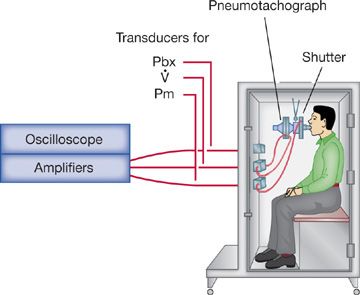
The pressure plethysmograph (Fig. 33-5) contains a pneumotachograph and transducer for measuring flow and volume, and two strain-gauge transducers, one for sensing pressure at the mouth (Pm) and the other for sensing pressure in the box (Pbx). A solenoid-operated shutter mechanism is situated between the mouthpiece and the pneumotachograph. The three transducers are connected to an amplifying and monitoring system so that box pressure (or lung volume) and mouth pressure are displayed simultaneously on the X and Y axes, respectively, of an oscilloscope (Fig. 33-6).
Figure 33-5 Constant-volume, variable-pressure plethysmograph used for measuring functional residual capacity and airway resistance. The device has a fixed volume. Thoracic gas volume changes associated with changes in alveolar pressure are reflected as changes in pressure within the plethysmograph.
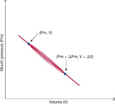
Figure 33-6 Pressure–volume loop obtained from a person seated in a body plethysmograph. Pressure at the mouth represents alveolar pressure; pressure in the box represents thoracic gas volume. After the shutter has closed at end-expiration (Pm, V), the subject attempts to inspire. Pm falls, and the pressure in the box increases. This increase in box pressure is calibrated in terms of an equivalent volume change. The new position of the trace at the end of the inspiratory effort is (Pm + ΔPm, V + ΔV). The slope of the loop depends on the volume of gas in the lungs when the shutter is closed (FRC).
In order to determine FRC, the patient, seated comfortably within the box with nose clip in place, is asked to breathe quietly through the mouthpiece. At the end of a quiet expiration, the shutter is closed and the patient is instructed to pant gently against it. The panting movements cause both mouth pressure and box pressure to change. With each inspiratory effort, as mouth pressure falls and gas in the lungs is rarefied, lung volume increases. Because the plethysmograph is a closed box, the increase in lung volume produces a corresponding increase in box pressure. With each expiratory effort, as lung volume decreases, box pressure falls. Because the shutter is closed while the measurements are made, mouth pressure equals alveolar pressure (PA). These oscillations in mouth pressure and box pressure or lung volume appear on the oscilloscope as a closed loop (Fig. 33-6). Measurement of the slope of this loop is used to determine the volume of gas in the lungs at the time of shutter closure – that is, TGV or VTG. When the occlusion occurs at resting, end-expiratory lung volume, the measurement yields FRC (see below).
Applying Boyle’s law to the plethysmographic determination of lung volume,

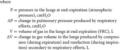
In the pressure plethysmograph, ΔV is sensed as a change in pressure within the box, and ΔP is determined from the change in mouth pressure during breathing efforts against the closed shutter.
Rearranging the above equation and solving for V yield
![]()
However, since ΔP is small compared to P (atmospheric pressure), it may be disregarded. The equation then becomes
![]()

Therefore, the only unknown in this equation is V, which can be calculated by incorporating values for barometric pressure and the inverse of the slope of the plot of mouth pressure versus box pressure (ΔP/ΔV).
Two methods for measuring static lung volumes using plethysmography have been standardized by the ATS and ERS. One entails shutter closure at FRC, followed by expiration to RV, and then an IC maneuver to TLC; the other method is shutter closure at FRC, followed by an IC maneuver to TLC, and then an expiratory vital capacity maneuver to RV.12 Application of each method may yield different calculations of lung volumes.13
Comparison of Methods
Compared to the dilution and washout techniques, body plethysmography is, by far, the fastest method available for determining FRC. Indeed, it enables several determinations to be made per minute. Although the equipment required for body plethysmography is more expensive than that required for the other methods, in a busy laboratory this technique generally proves to be more economical because of the time saved and the additional uses to which the equipment can be put (e.g., measurement of airway resistance; see Airway Resistance). Technically, the test is only slightly more difficult than the inert gas dilution method.
Sources of error inherent in the use of body plethysmography and discrepancies between results obtained by body plethysmography and the inert gas techniques should be noted. In patients with COPD14 or asthma,15 values for FRC obtained by body plethysmography may be artifactually high because of pressure differences between the mouth and alveoli generated during panting across narrowed airways. Consequently, pressures recorded at the mouth during shutter occlusion of the airway underestimate changes in alveolar pressure. Overestimation of TLC using body plethysmography appears to be greatest in patients whose FEV1 (see below) is less than 30% predicted.16
The inert gas dilution and washout methods are similar both in principle and in results. The values for FRC with these techniques match those from the body plethysmograph except in persons in whom considerable areas of the lungs are poorly ventilated, usually due to obstructive airway disease. In these individuals, complete mixing or washout of the indicator gas is very slow, at times requiring 45 minutes or longer. Because of the slow equilibration of gas concentrations in the poorly ventilated areas, the usual time allotted for the test is inadequate, resulting in a lower value for FRC by the washout methods than by body plethysmography. One strategy commonly used to deal with this problem is to prolong the washout time. The primary advantage of these techniques over body plethysmography is that they can be used in persons for whom the plethysmograph is impractical – for example, those with marked obesity, skeletal abnormalities, or claustrophobia.
 TEMPERATURE CORRECTION FACTORS
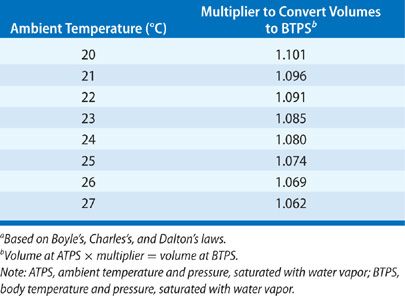
By convention, all lung volumes described above and airflows (see below) are expressed in terms of body temperature and pressure, saturated with water vapor (BTPS). This practice enables direct comparison of pulmonary function data from laboratories operating at different ambient temperatures and altitudes. To convert the volume of gas collected in a volume-type spirometer under ambient conditions (i.e., ambient temperature and pressure, saturated with water vapor, or ATPS) to BTPS, a conversion factor is applied (Table 33-3). Previously, it was presupposed that air entering a spirometer was cooled immediately to ambient temperature and remained saturated with water vapor (ATPS). Under this assumption, only ambient temperature was considered in determining the appropriate correction factor. However, studies have addressed the assumption that expired gas is immediately cooled,17,18 as well as the practical consequences of temperature correction errors. The ATS recommends temperature correction of results from volume-type spirometers based on measured gas temperature at the time of testing.
 RADIOGRAPHIC ASSESSMENT OF LUNG VOLUME
Although initial reports describing use of radiographic techniques to measure lung volumes date back over 40 years, these methods have not found widespread use in adult populations. More sophisticated computerized tomographic (CT) applications have demonstrated good correlation with plethysmographic and gas dilution techniques in normals. However, significant differences may be observed in patients with COPD,19 in whom TLC determinations using plethysmography may be up to 2 L greater than TLC assessed with CT scanning.20
STATIC MECHANICAL PROPERTIES OF THE RESPIRATORY SYSTEM
Exploration of the elastic properties of the respiratory system and their effect on lung volumes and work of breathing began in earnest during the earlier part of the 20th century. Although the groundwork had been laid centuries before (by Robert Hooke’s The Theory of Springs in 1678), between 1923 and 1956 investigators provided a wealth of information about the elastic properties of the respiratory system and its components and the work done in overcoming these elastic forces during breathing.
 STATIC COMPLIANCE OF THE LUNGS
The elastic properties of the lungs are determined by relating the change in the volume of air contained in the lungs to the corresponding change in the recoil force of the lungs. Change in lung volume is most easily measured by determining the volume of gas inspired or expired at the mouth. Although expedient, this approach to determining the elastic properties of the lungs can underestimate the change in lung volume when incorporated into techniques (see below) that require the subject to expire gently against a closed shutter, a maneuver that compresses thoracic gas. However, the problem can be circumvented by placing the subject in a volume plethysmograph that uses a spirometer attached to the plethysmograph to record changes in TGV due to gas compression.
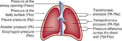
The recoil force of the lungs, measured as the transpulmonary pressure (Fig. 33-7), is the difference between the alveolar and pleural pressures (PA and Ppl, respectively). Alveolar pressure is determined as the pressure at the airway opening (Pao) – that is, the mouth – when airflow is arrested and the glottis is open. The pleural pressure is determined indirectly by measuring the pressure in the esophagus using an esophageal balloon catheter. This technique, first introduced in 1949, has been improved over the years and provides accurate reflections of changes in pleural pressure at all lung volumes except those below FRC.21
Figure 33-7 Schematic representation of the chest depicting pressure terms and gradients used in analysis of the mechanics of breathing. The expressions for individual pressure measurements on the left are relative to atmospheric pressure. Pleural pressure (Ppl) is not routinely measured directly but is approximated by esophageal pressure (Pes) measured with a balloon catheter.
A thin rubber balloon, about 10 cm long, is placed over a small-diameter polyethylene catheter. Several holes in the terminal portion of the catheter allow pressure to be transmitted from the balloon, through the catheter, to a transducer. The balloon is positioned in the lower third of the esophagus, where esophageal pressure and, therefore, balloon pressure accurately reflect the pressure acting on the lung surface (pleural pressure). Use of an elongated balloon of low volume helps to minimize changes in pressure due to esophageal contractions. By conveying mouth pressure and esophageal pressure to opposite sides of a differential pressure transducer, an output signal is generated that is proportional to the difference between these two pressures – that is, the transpulmonary pressure (PA – Ppl).
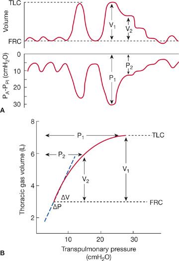
To determine the elastic properties of the lungs, the patient, with esophageal balloon in place, is seated in a closed body plethysmograph. The patient then breathes ambient air through a tube to the outside until the volume trace, inscribed by the plethysmograph spirometer, indicates that the end-expiratory level is stable. At this juncture, the patient is instructed to first inspire slowly to TLC and then to expire slowly to the resting end-expiratory level (FRC). This maneuver is then repeated; during the second expiration, the shutter is activated to occlude the airway intermittently. Since each closure of the shutter interrupts the expiration briefly, the recorded trace of expiratory volume versus time displays a staircase pattern (Fig. 33-8A). The plateau resulting from each closure of the shutter marks a finite period of zero change in lung volume as the lungs empty during expiration. Associated with each plateau is a corresponding plateau in transpulmonary pressure.
Figure 33-8 Measurement of the elastic properties of the lungs. A. Recordings of changes in lung volume and transpulmonary pressure (PA – Ppl) using the esophageal balloon technique described in the text. Simultaneous measurements of volume and pressure are obtained during periods of arrested airflow at lung volumes ranging from TLC to just below FRC. B. Thoracic gas volume is plotted on the ordinate and transpulmonary pressure on the abscissa. The curve formed by the plot using values from A describes the elastic properties of the lungs. The slope of the line, ΔV/ΔP, over the range of the tidal volume is the static compliance of the lungs.
The relationship between the change in volume and the change in pressure is a measure of the recoil force of the lungs at each of the lung volumes that are registered (Fig. 33-8B). The resulting curve provides several useful indices of the elastic behavior of the lungs. The slope of the curve over the range corresponding to the tidal volume is the static lung compliance. The transpulmonary pressure attained at TLC is the maximal static recoil pressure. The ratio of the maximal static recoil pressure to the corresponding maximal lung volume is the coefficient of retraction. However, since these values are derived from only small segments of the curve, inspection of the total static pressure–volume curve remains the most comprehensive means of assessing the elastic properties of the lungs.
 STATIC COMPLIANCE OF THE CHEST WALL
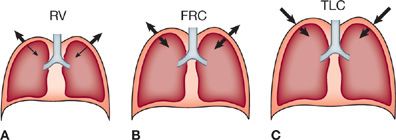
Functionally, the chest wall includes the bony thorax, intercostal muscles, overlying soft tissue, pleura, and diaphragm. The chest wall is distensible and has its own distinctive elastic properties. In the normal, end-expiratory, resting position of the respiratory system (FRC), the inward recoil of the lung is balanced by the outward recoil of the chest wall (Fig. 33-9B). As the volume of the thoracic cavity enlarges progressively during inspiration from FRC to TLC, the outward recoil pressure of the chest wall lessens, becoming zero at approximately 70% of TLC; beyond this point, the chest wall begins to recoil inwardly (Fig. 33-9C). Conversely, as the chest wall is compressed below FRC by the action of the expiratory muscles, the natural outward recoil tendency is increased (Fig. 33-9A).
Figure 33-9 Schematic depiction of elastic recoil vectors across the lung and chest wall as determined by the level of inflation. A. At RV, the outwardly directed recoil pressure of the chest wall is large and the inwardly directed recoil pressure of the lung is small. B. At FRC, the recoil pressures of the lung and chest wall are equal and in opposite directions. C. At TLC, both recoil pressures are directed inward, and each contributes substantially to the overall recoil pressure of the respiratory system.
In practice, assessment of the elastic properties of the chest wall is accomplished by first determining the compliance curve of the respiratory system as a whole and then subtracting the contribution of the lungs. For a given lung volume, the pressure across the chest wall, Ppl – Pbs (Fig. 33-7), is simply the difference between the transthoracic (PA – Pbs) and transpulmonary (PA – Ppl) pressures. As indicated above, Ppl is determined using an esophageal balloon catheter.
 ELASTIC PROPERTIES OF THE RESPIRATORY SYSTEM AS A WHOLE
The elasticity of the respiratory system as a whole is determined by measuring the change in volume resulting from a change in pressure applied to the system – that is, the transthoracic pressure (PA – Pbs) – while the respiratory muscles are completely relaxed.
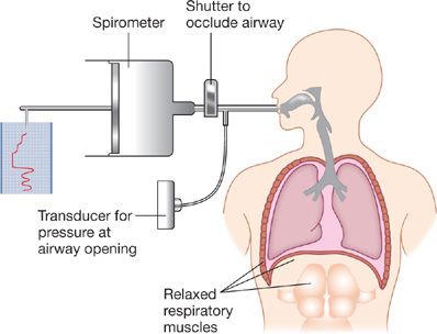
The first method used for this evaluation employed the relaxation technique described by Rahn and associates.22 The subject breathes quietly into an apparatus consisting of a spirometer, a shutter, and a pressure transducer connected to the subject’s side of the shutter (Fig. 33-10). After a period of quiet breathing, the subject is instructed to inspire maximally; the shutter is closed at peak inspiration, and the subject is then asked to relax the respiratory muscles completely while keeping the glottis open. Periodically, the shutter is opened, allowing a small volume of air to move from the subject into the spirometer; the shutter is then closed again. This maneuver is repeated until FRC is reached. During the periods of arrested airflow, pressure at the mouth (Pao) is equal to the pressure in the alveoli (PA). Provided the pressure at the body surface is atmospheric and the respiratory muscles are completely at rest, this value represents transthoracic pressure. In practice, however, full relaxation of the respiratory muscles is difficult, and a contribution by them to the pressure at the airway opening is frequently unavoidable.
Figure 33-10 Relaxation technique for measurement of elastic recoil pressure of the respiratory system. After a period of normal tidal volume breathing, the subject inspires to TLC. A shutter in the airway is closed, and the subject relaxes his or her respiratory muscles. The shutter is periodically opened, permitting exhalation of a small volume of air measured by the spirometer. Airway pressures are recorded at times of shutter closure (i.e., during no airflow, when mouth pressure equals alveolar pressure). A pressure–volume curve is then constructed from the simultaneously recorded values for pressure and volume.
A more practical technique entails the application of continuous positive pressure to the airways during spontaneous breathing. The subject breathes quietly into a water-sealed spirometer until a constant end-tidal level is achieved. A weight is then placed on the spirometer bell to increase the pressure in the respiratory system and, thereby, to raise the resting end-expiratory lung volume. This procedure is repeated using several different weights so that a pressure–volume curve of the total respiratory system can be constructed.
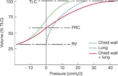
The individual pressure–volume curves for the lungs and chest wall and the composite curve for the intact respiratory system are shown in Figure 33-11. As illustrated, the elastic recoil of the chest wall alone is determined by subtracting the recoil pressure of the lung from that of the total respiratory system. Chest wall elasticity is an important determinant of the subdivisions of lung volume and the overall compliance of the respiratory system; the latter is, in turn, an important determinant of the work of breathing.
Figure 33-11 The pressure–volume curves of the respiratory system and its components. The elastic recoil pressures of the total respiratory system (solid line) over the vital capacity range are the sum of the recoil pressures of the lung (dashed line) and chest wall (dotted line). At FRC, the chest wall recoil pressure is counterbalanced by the lung recoil pressure. The net result is a total system recoil pressure of 0. The total system recoil pressure is obtained by relaxation pressure or continuous positive-pressure breathing techniques. The chest wall recoil pressure is calculated as the difference between the recoil pressure of the entire respiratory system and the recoil pressure of the lungs.
Several features of the pressure–volume relationships shown in Figure 33-11 are worth emphasizing. As lung volume approaches RV, the elastic recoil pressure of the respiratory system is largely due to the outwardly directed recoil pressure of the chest wall. At RV, the contribution of the lung to the recoil pressure of the respiratory system is minimal. At the other extreme of lung volume, TLC, elastic recoil pressure is high and directed inwardly, due to the combined elastic recoils of the lung and chest wall. At FRC, the outwardly directed recoil of the chest wall balances the inwardly directed recoil of the lung, and the transthoracic pressure is zero (i.e., PA – Pbs = 0). Indeed, the system “comes to rest” at FRC because of the counterbalancing of these forces at that volume. Since alveolar pressure at FRC is zero, no pressure gradient exists for airflow. Therefore, the system remains stationary until acted upon by the muscles of inspiration or expiration.
 ELASTIC PROPERTIES OF THE RESPIRATORY SYSTEM IN HEALTH AND DISEASE
The elastic properties of the respiratory system are altered by a wide variety of diseases that can affect the lung parenchyma or chest wall, either selectively or in concert. Most instances of clinically significant reductions in static compliance are due to abnormalities in the lung. The two standard clinical measures of the elastic properties of the lung are static lung compliance and maximal static recoil pressure.
Static lung compliance, Cst,L, is determined over the linear portion of the pressure–volume curve, between FRC and a lung volume corresponding to FRC plus 0.5 L. Normal values vary among laboratories, ranging from 0.147 to 0.375 L/cmH2 O, with a mean of 0.262 L/cmH2O. Some variability is related to age and sex; Cst,L decreases with age and is higher in males than in females.
Maximal static recoil pressure is the recoil pressure at TLC. Once again, normal values vary. Data from one series of 51 normal subjects.23 are shown in Table 33-4.
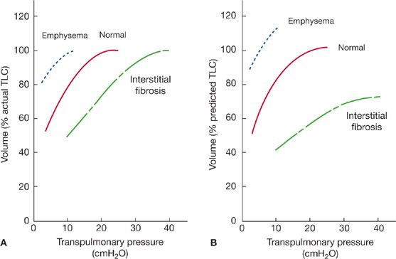
In disease states characterized by an increased elastic recoil pressure, such as diffuse interstitial fibrosis, the pressure–volume curve is shifted to the right and the static lung compliance decreases (Fig. 33-12A and B). The increased elastic recoil pressure contributes to a decrease in FRC and TLC. By expressing the volume axis of the pressure–volume curve in terms of percent predicted TLC (Fig. 33-12B), instead of absolute TLC (Fig. 33-12A), the reduction in maximal lung volume is clearly evident; that is, maximal recoil pressure is increased, despite the reduced TLC.
Figure 33-12 Pressure–volume curves of the lungs in health and disease. A. Volume expressed as percent of actual TLC. Differences in transpulmonary pressures in normal and diseases states are evident. Changes in lung volume that occur with disease are demonstrated on the plots. B. Volume expressed as percent of predicted TLC. In addition to the differences in transpulmonary pressures, alterations in lung volumes in the disease states are evident.
In contrast to the effects of fibrosis, emphysema, which destroys alveolar walls and enlarges alveolar spaces, reduces lung elastic recoil pressure (Pel). This change increases both TLC and FRC. The shift of the pressure–volume curve upward and to the left (Fig. 33-12A and B) indicates that lung compliance increases and that the maximal recoil pressure decreases. If the volume axis is expressed as percent predicted TLC (Fig. 33-12B), the increase in lung volume is more clearly demonstrated.
As noted previously, disorders affecting primarily the chest wall can also significantly alter the elastic properties of the respiratory system. Among these are obesity, kyphoscoliosis, and fibrothorax. These disorders limit chest wall excursion and lung expansion and reduce FRC. In addition, they produce decreases in static compliance of the lung and chest wall and maximal recoil pressure.
RESPIRATORY MUSCLE STRENGTH
Ventilatory performance depends not only on the mechanical properties of the lungs and chest wall, but also on the strength of the respiratory muscles. Evaluation of respiratory muscle strength was undertaken as early as the mid-19th century. Subsequently, using simplified methods of measurement, Black and Hyatt established normal values (Table 33-5).24
TABLE 33-5 Prediction Equations and Lower Limits of Normal for Maximal Inspiratory (PImax) and Maximal Expiratory (PEmax) Pressures (cmH2O)a

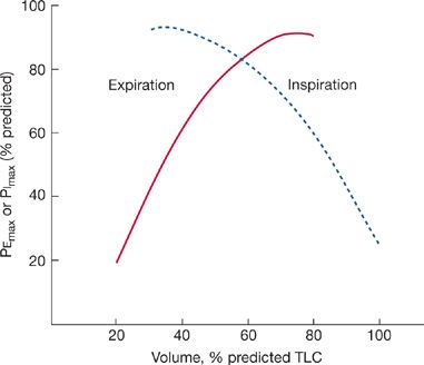
The maximal pressure generated by an isometric contraction varies directly with the resting length of the muscle. Consequently, values for maximal inspiratory and expiratory pressures depend on the lung volume at which the tests are performed (Fig. 33-13).25 When TLC is less than 70% of the predicted value, the maximal expiratory pressure will be low. Similarly, when RV exceeds 40% of the predicted TLC, the maximal inspiratory pressure will be low.
Figure 33-13 Effect of lung volume on maximal inspiratory (dashed line) and maximal expiratory (solid line) pressures. See text for discussion.
The only equipment required for measurement of maximal inspiratory or expiratory pressure is an aneroid vacuum and pressure gauge. To determine maximal expiratory pressure, the patient is urged to inspire fully to TLC and then to expire as forcefully as possible into the gauge. The highest pressure attained and held for at least 1 second is the maximal expiratory pressure (PEmax). The maximal inspiratory pressure (PImax) is determined by having the patient inspire maximally from the gauge after having expired completely to RV. The value recorded is the lowest pressure attained and held for at least 1 second.
Measurement of maximal static respiratory pressures is particularly important in evaluating respiratory muscle weakness in patients with neuromuscular disease, as described in Chapters 84 and 85. In such patients, spirometric tests are often normal, despite respiratory muscle weakness, because maximal pressures are not required to achieve maximal expiratory flow rates (see Flow–Volume Curves).
Another useful function of these measurements is in examining patients whose coordination in performing spirometry or whose degree of motivation is suspicious In such patients, determination of maximal pressures is often helpful in determining whether optimal efforts are being expended during pulmonary function testing (see Approach to Interpreting Commonly Performed Pulmonary Function Tests).
DYNAMIC MECHANICAL PROPERTIES OF THE RESPIRATORY SYSTEM
The static tests of pulmonary function described in the previous section are based on measurements of volume and pressure made while airflow is arrested. These static tests are particularly useful in defining the elastic properties of the respiratory system. Considerable additional information can be gained from tests done during airflow – that is, under “dynamic” conditions.
Although measurements of static lung volumes began about 300 years ago, the assessment of pulmonary function during airflow began in 1933, when the test now known as the maximal voluntary ventilation (MVV) was first proposed. This test did not become popular until a few years later, when Cournand and Richards developed regression equations to determine normal values. Subsequently, investigators proposed that the volume of air expired during specific time intervals be determined. In 1955, determination of the average airflow during the middle half of a forced expiratory vital capacity was described. Determination of these indices of dynamic lung function is now generally part of the battery of tests, both static and dynamic, included under the designation spirometry.
The more practical tests of dynamic function can, for convenience, be divided into four categories: FVC, flow–volume curves, MVV, and airway resistance. Other dynamic tests, including assessment of airway reactivity and the function of small airways, will be considered separately.
 FORCED VITAL CAPACITY
Both expiratory and inspiratory measurements of the FVC are routinely made in pulmonary function laboratories. Unless otherwise specified, FVC refers to the forced expiratory maneuver.
Forced Expiratory Vital Capacity
The forced expiratory vital capacity is measured during expiration. The maneuver entails two steps: a full inspiration to TLC, followed by a rapid, forceful, maximal expiration (to RV) into a spirometer. The forced expiratory vital capacity (FVC) is normally equal to the relaxed or slow vital capacity (VC). However, a discrepancy between FVC and VC appears in obstructive disease of the airways: the FVC is less than the VC.
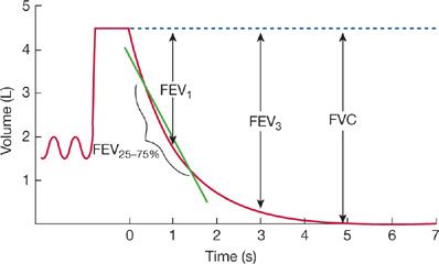
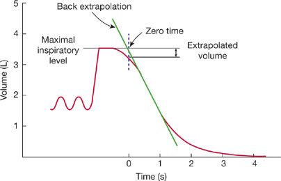
The relationship between expired volume and time during an FVC maneuver is used to determine airflow during expiration and the volume of air expired within designated intervals; these values provide an indirect measure of the flow-resistive properties of the lung. The FVC is displayed in one of the two ways: expired volume plotted against time (Fig. 33-14) or airflow plotted against lung volume – that is, an expiratory “flow–volume curve” (see below). The normal volume–time display of the FVC consists of a smooth curve with a gradually and progressively decreasing slope. Irregularities in the curve suggest either a failure of coordination or a suboptimal effort. At times, the onset of the forced expiration is unclear (Fig. 33-15) because of hesitation on the part of the patient. When this occurs, the start of expiration (“zero time”) is determined with the “back extrapolation” method (Fig. 33-15).8 A tangent taken through the part of the curve with the steepest slope is extrapolated back to the maximal inspiratory volume; the point of intersection is considered to be the time of onset of expiration.
Figure 33-14 Forced expiratory vital capacity maneuver. After an initial period of tidal volume breathing, the patient inspires maximally to TLC and then exhales as rapidly and as forcefully as possible into a spirometer. Shown on the left of the tracing are a series of tidal volume breaths and the maximal inspiration to TLC. The forced expiration begins at time 0. Nearly all the volume is exhaled in the first 3 seconds of the maneuver. The values for FVC, FEV1, and FEV3 are measured from the maximal inspiratory level. The FEF25–75% is the slope of the line connecting the points on the volume–time trace that correspond to 25% and 75% of the FVC.
Figure 33-15 Technique of back extrapolation for determining the zero time in calculation of FEV1. Zero time is determined as the point of intersection of a tangent drawn through the steepest portion of the spirogram and a line drawn horizontally through the maximal inspiratory level.
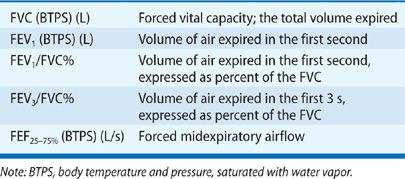
Several values are commonly determined from the volume–time plot of the FVC (Table 33-6, Fig. 33-14): (1) the volume expired in the first second, expressed either as an absolute volume (FEV1) or as a percentage of the FVC (FEV1/FVC%); (2) the volume expired in the first 3 seconds, expressed either as an absolute volume (FEV3) or as a percentage of the FVC (FEV3/FVC%); and (3) the forced midexpiratory flow rate (FEF25–75%). The FEF25–75% is determined by locating the points on the volume–time curve corresponding to 25% and 75% of the FVC and then calculating the slope of a straight line passing through those two points. The slope of this line represents the average airflow over the midportion of the FVC.
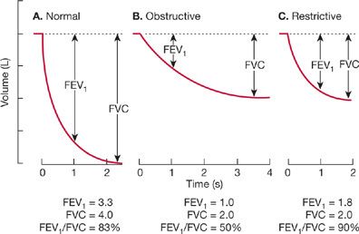
Although the relaxed or slow vital capacity (VC) may be normal or only modestly reduced in patients with obstructive disease of the airways, the volume–time relationship of the FVC maneuver is usually distinctly abnormal in such patients (Fig. 33-16A and B). Most obvious is a flattening of the slope of the curve at any given lung volume, reflecting the reduced airflow. In addition, the duration of the forced expiratory maneuver is prolonged. Normally, expiration is complete within 6 seconds; in obstructive airway disease, expiratory airflow may continue for 10 to 12 seconds. These changes in the expiratory airflow reduce the FEV1 and FEV3, the FEV1/FVC%, the FEV3/FVC%, and the FEF25–75%.
Figure 33-16 Representative spirograms from a normal subject (A), a patient with obstructive lung disease (B), and a patient with restrictive lung disease (C), obtained during a forced expiratory vital capacity maneuver. In the normal subject, expiration is completed within 3 seconds, and 83% of the volume is expired in the first second (FEV1/FVC% = 83). In the patient with obstructive disease, expiration is prolonged, and only half the volume is expired in the first second (FEV1/FVC% = 50). In the patient with restrictive disease, although the magnitude of the reduction in exhaled volume is the same as in the obstructed patient, most of the volume is exhaled within the first second (FEV1/FVC% = 90).
Restrictive lung disorders reduce the slow vital capacity. However, the configuration of the volume–time relationship may not be abnormal (Fig. 33-16C). Although the FEV1 and FEV3 are reduced because of the reduced vital capacity, the FEV1/FVC% and FEV3/FVC% remain normal or even exceed normal values. Often, because of the reduced vital capacity, the FEF25–75% is also less than predicted.
Forced Inspiratory Vital Capacity
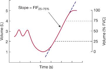
Measurement of the forced inspiratory vital capacity (FIVC) consists of two steps: (1) full expiration to RV, followed by (2) a rapid maximal inspiratory effort (Fig. 33-17). The rate of airflow over the middle half of the forced inspiratory vital capacity (FIF25–75%) is determined using a procedure similar to that described previously for the FEF25–75%.
Figure 33-17 Forced inspiratory volume–time curve. The FIF25–75% is the slope of a line between the points on the trace corresponding to 25% and 75% of the inspired volume.
In normal subjects, the FIF25–75% is greater than the FEF25–75%. Since inspiratory flow is more dependent on effort than is expiratory flow, a fall in the FIF25–75% is usually a more sensitive indicator of respiratory muscle dysfunction or a suboptimal effort than is the FEF25–75%. When airway resistance is high, a disproportionate fall in FIF25–75% relative to FEF25–75% suggests an extrathoracic site of airway obstruction (see Approach to Interpreting Commonly Performed Pulmonary Function Tests).
 FLOW–VOLUME RELATIONSHIPS
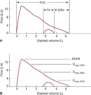
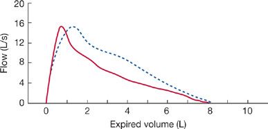
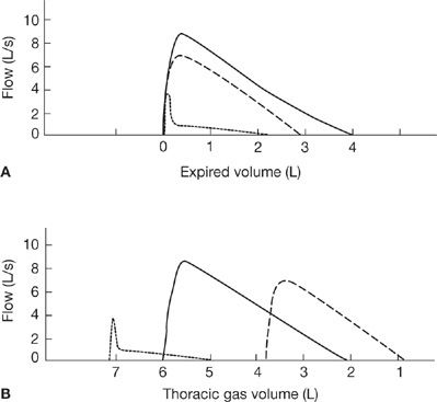
In addition to analysis of the relationship between volume and time depicted on a spirogram, examination of the relationship between flow and volume provides useful information about lung function. A flow–volume curve, which shows the relationship between lung volume and maximal airflow as lung volume changes during a forced expiration, is shown in Figure 33-18. The test comprises four phases of breathing into a spirometer: (1) tidal breathing for several breaths, (2) a maximal inspiratory effort to TLC, followed by (3) a maximal expiration to RV done as forcefully and quickly as possible, and (4) another maximal inspiratory effort to TLC. Volume is displayed on the horizontal axis and airflow on the vertical axis. Airflow is measured at the mouth using a pneumotachograph; volume is measured either by integrating the pneumotachographic record during expiration or as a change in TGV, determined by a pressure-corrected flow plethysmograph. The records obtained by the two techniques for determining volume differ because the body plethysmograph senses compression of intrathoracic gas during a forced expiration, whereas measurements of volume made at the mouth do not (Fig. 33-19). Differences between curves obtained with the two techniques for measuring volume are most marked in patients with airway obstruction in whom considerable gas compression occurs during a forced expiration.
Figure 33-18 Flow–volume plots during forced expiration (outer trace) and quiet expiration (inner trace). A. The subdivisions of lung volume. B. The common flow measurements. PEFR = peak expiratory flow rate; ![]() max,75%,
max,75%, ![]() max,50%, and
max,50%, and ![]() max,25% = flows at 75%, 50%, and 25% of the vital capacity, respectively.
max,25% = flows at 75%, 50%, and 25% of the vital capacity, respectively.
Figure 33-19 Comparison of the flow–expired-volume curve (solid line) with a simultaneously recorded flow–thoracic-gas-volume curve (dashed line). The difference between the two curves results from the compression of gas in the lungs during a forced expiration.
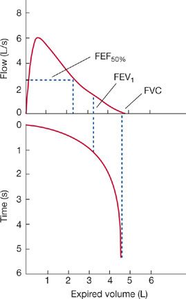
For the sake of comparison, tracings of flow versus volume and volume versus time, recorded during the same FVC maneuver and aligned by using a common volume axis as the abscissa, are shown in Figure 33-20. Selected measurements are more evident in one tracing or the other – for example, maximal expiratory flow in the flow–volume curve and volume expired in 1 second (FEV1) in the volume–time curve.
Figure 33-20 Flow–volume and volume–time curves depicting the same forced expiration aligned along a common volume axis (abscissa). Points corresponding to the FEV1, FVC, and FEF50% obtained from the volume–time plot are shown on the flow–volume curve.
Comparison of serial curves from a single person or curves from different subjects requires that the curves be aligned on the volume (horizontal) axis so that points of maximal inspiration or maximal expiration coincide. As may be seen in Figure 33-21A, which illustrates typical curves from a normal subject and two patients, one with pulmonary fibrosis and the other with obstructive airway disease, the information provided by this form of representation is limited; that is, the vital capacities and airflows from the patients are abnormally low. The limitation stems from the fact that the change in volume during expiration is shown relative to the maximal inspiratory level rather than to an absolute volume of gas in the lungs – that is, RV or TLC. When RV or TLC is known so that absolute volumes can be plotted on the horizontal axis (Fig. 33-21B), additional insight is gained into the flow–volume relationship depicted in Figure 33-21B. The patient with obstructive disease of the airways manifests a reduction in expiratory airflow at elevated lung volumes, which should enhance airflow. In contrast, the reduced rate of airflow in the patient with pulmonary fibrosis is normal, or even supranormal, when the lung volume at which the airflow occurs is taken into account; that is, the reduced airflow is primarily a function of the reduced lung volume, rather than of airway obstruction.
Figure 33-21 Airflow at different lung volumes. A. Flow–volume curves aligned at TLC. B. Flow–volume curves displayed relative to thoracic gas volume. Although the curves aligned at TLC (A) show striking differences in the pattern of airflow, they provide no insight into the relationship between lung volumes and airflow. See text for discussion.
 MAXIMAL VOLUNTARY VENTILATION
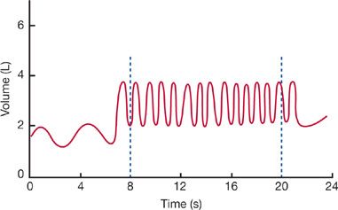
The previous considerations of dynamic lung function focus on a single timed maximal expiratory or inspiratory maneuver. In contrast, the MVV depends on the movement of air into and out of the lungs during continued maximal effort throughout a preset interval (Fig. 33-22). The MVV is a simple, informative test that provides an overall assessment of effort, coordination, and the elastic and flow-resistive properties of the respiratory system.26,27
Figure 33-22 Maximal voluntary ventilation (MVV). After a period of relaxed breathing, the subject breathes rapidly and as forcefully as possible. The total volume of air inspired over 12 seconds and expressed in L/min is the MVV.
In performing the test, the patient is urged to breathe as hard and as fast as possible. As a rule, the patient automatically adjusts frequency and tidal volume for optimal performance. However, extremes of frequency or tidal volume are to be avoided, since neither panting nor slow deep breathing leads to the highest possible values. The total volume that is expired during a 12-second interval, expressed in liters per minute (BTPS), is the MVV. In some patients the test cannot be done because of an inability to continue the necessary effort for 12 seconds.
A normal value for MVV indicates that the overall integrated performance of the respiratory system is intact, thereby excluding moderate to severe restrictive or obstructive disease. In addition, a normal value suggests that the elastic and flow-resistive properties of the respiratory system, respiratory muscle strength, coordination of respiratory performance, and motivation of the patient are all normal. Although this test is very useful in detecting overall disturbances in integrated performance and diffuse tracheobronchial and pulmonary parenchymal diseases, other tests are required to pinpoint specific disorders.
The difference between the MVV and the resting minute ventilation is the breathing reserve. At one time, a low breathing reserve was correlated with the breathlessness in lung diseases. However, this determination is now primarily of historical interest.
 RESPIRATORY RESISTANCE
Total respiratory resistance (Rrs) is the resistance to airflow and chest expansion offered by the airways (Raw), chest wall (Rw), and lung tissue (Rti):

The overall resistance of the respiratory system can be determined with a technique employing forced oscillation (see Small-Airway Function). However, further methodologic refinements permitting determination of pulmonary resistance – the sum of airway and tissue resistances (Raw + Rti) – have not proved to be worthwhile clinically, particularly since measurement of transpulmonary pressure with an esophageal balloon is necessary. Other variations of the determination of resistance measurements have also been explored. However, the only clinically useful measurement of resistance is airway resistance, which is now routinely determined in pulmonary function laboratories.
 AIRWAY RESISTANCE
Airway resistance (Raw) is defined as the ratio of the driving pressure (P) for flow to the actual rate of airflow (![]() ) along the airways – that is, the mouth, nasopharynx, larynx, and central and peripheral airways:
) along the airways – that is, the mouth, nasopharynx, larynx, and central and peripheral airways:
![]()
where ΔP, the drop in pressure over the entire length of the airways, is determined as the difference between alveolar pressure (PA) and pressure at the mouth (Pm) or airway opening (Pao).
Although airflow and pressure at the airway opening are easily measured, the difficulty in measuring alveolar pressure prevented the routine determination of airway resistance until DuBois and colleagues introduced the plethysmographic technique in 1956.28
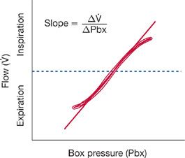
With this technique, the patient, seated in the body plethysmograph, pants at a rate of about two breaths per second while airflow is measured using a pneumotachograph. During inspiration and expiration, gas in the alveoli is alternately rarefied and compressed, causing changes in pressure within the sealed plethysmograph. The relationship between plethysmograph pressure and airflow during the panting maneuver is displayed on the X and Y axes of an oscilloscope (Fig. 33-23).
Figure 33-23 Plot of airflow (![]() ) versus body plethysmograph pressure (Pbx). The slope of this curve, in the range of 0 to 0.5 L/s of inspiratory flow, divided into the slope of the loop obtained when the shutter is closed (see Fig. 33-7) provides a measure of airway resistance (Raw).
) versus body plethysmograph pressure (Pbx). The slope of this curve, in the range of 0 to 0.5 L/s of inspiratory flow, divided into the slope of the loop obtained when the shutter is closed (see Fig. 33-7) provides a measure of airway resistance (Raw).
While the panting continues, a shutter at the airway opening is closed so that airflow is transiently interrupted. Using the technique employed in the determination of FRC, changes in pressure in the plethysmograph (equivalent to changes in lung volume) and at the mouth are displayed on the X and Y axes, respectively, of the oscilloscope (Fig. 33-6). However, since airflow is zero while the shutter is closed, the pressure at the mouth equals alveolar pressure (Pao = PA).
Panting while the shutter is open allows the determination of the relationship between airflow (![]() ) and plethysmograph pressure (Pbx) – that is,
) and plethysmograph pressure (Pbx) – that is, ![]() /Pbx. Similarly, panting against a closed shutter enables the determination of the relationship between alveolar pressure (PA) and plethysmograph pressure – that is, PA/Pbx. Airway resistance is calculated by dividing the slope of the loop obtained by plotting PA versus Pbx while the shutter is closed by the slope obtained by plotting
/Pbx. Similarly, panting against a closed shutter enables the determination of the relationship between alveolar pressure (PA) and plethysmograph pressure – that is, PA/Pbx. Airway resistance is calculated by dividing the slope of the loop obtained by plotting PA versus Pbx while the shutter is closed by the slope obtained by plotting ![]() versus Pbx while the shutter is open:
versus Pbx while the shutter is open:


Raw is measured during a panting maneuver for several reasons:29 (1) The rapid respiratory frequency in panting circumvents the poor low-frequency response characteristics of many plethysmographs. (2) The small inspired and expired volumes minimize temperature fluctuations in the plethysmograph that would otherwise occur as tidal breaths of air at body temperature are exchanged with breaths of air at room temperature. (3) During panting, the glottis remains open, thereby minimizing its contribution to overall airway resistance. Use of plethysmographs linked to microprocessors that automatically correct for temperature-related volume differences has made possible the determination of airway resistance during quiet breathing instead of during panting.
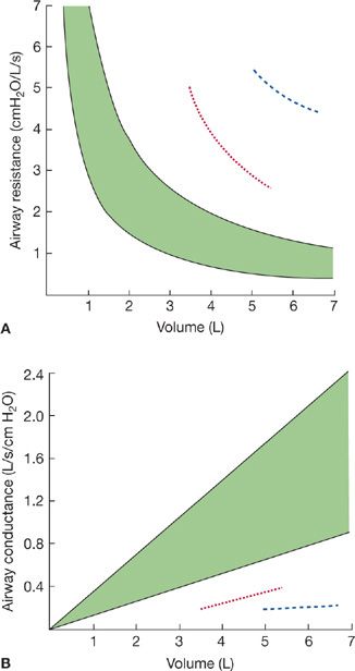
Airway resistance varies inversely with lung volume; it is low at large lung volumes and increases curvilinearly as lung volume and, consequently, airway diameters are reduced (Fig. 33-24A).30 In contrast, the inverse of airway resistance, airway conductance, is linearly related to lung volume (Fig. 33-24B). Interpretation of a given value for airway resistance or airway conductance requires that the lung volume at which the measurement is made be taken into account. Specific conductance (SGaw) is calculated by dividing airway conductance by the lung volume.
Figure 33-24 The relationship between airway resistance (A) and airway conductance (B). The shaded area represents the predicted normal range. Values are shown for an asthmatic patient before (dashed line) and after (dotted line) bronchodilator therapy. Airway resistance increases as lung volume decreases. Conversely, airway conductance, the inverse of resistance, decreases as lung volume decreases.
Defining the range of normal for Raw is difficult because of the lack of data obtained from populations sorted into smoking and nonsmoking groups and because of the inter- and intraindividual variations of Raw with lung volume. One classification scheme proposed for defining normal and abnormal Raw in adults in whom FRC exceeds 2 L is given in Table 33-7.
