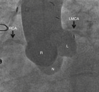
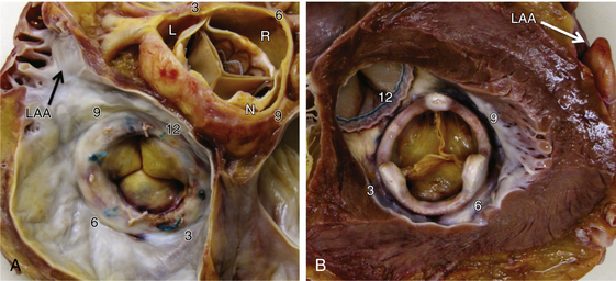
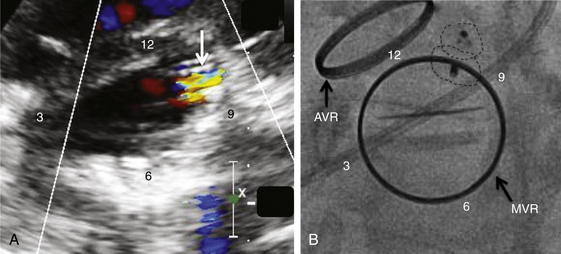
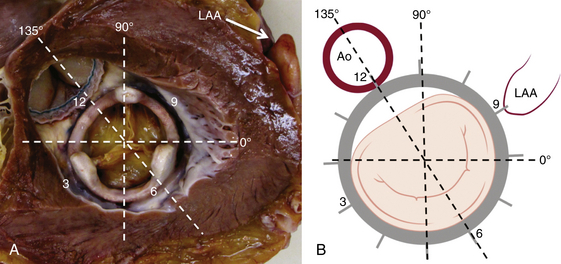
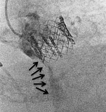
Chapter 12 Paravalvular leak (PVL) complicating mechanical or bioprosthetic surgical valve replacement is an uncommon but occasional occurrence. Various series have demonstrated an incidence of 2% to 12% after mitral valve replacement (MVR) and 1% to 5% after aortic valve replacement (AVR). Furthermore, transcatheter aortic valve replacement (TAVR) is a burgeoning technology, with moderate to severe aortic regurgitation (AR) in up to 17% of patients, the majority of whom have paravalvular AR (PAR).1 Given the magnitude of individuals in the United States and worldwide who undergo each of these operations, there are a large number of patients each year who suffer from PVL. Most patients with PVL need treatment within the first year after valve replacement.2 These patients usually suffer from symptoms of congestive heart failure (CHF) (85%), though hemolysis is also common (13% to 47% of patients).3 The risk for PVL is greater for mechanical prostheses, and it is higher among patients with calcified annuli, those undergoing valve replacement for infective endocarditis, and patients with a history of previous valve surgery in the same position. Each of these factors provides a predisposition to improper suturing of the valve ring into the annulus. As a result, structural interventionalists have become increasingly interested in developing percutaneous methods for PVL closure. Since the first reports of the procedure in 1992, a number of series have been published with encouraging rates of procedural success and good clinical outcomes.4–7 This chapter will provide an overview of the imaging, techniques, devices, and outcomes of percutaneous mitral and aortic PVL closure. Although not specifically addressed, closure of tricuspid valve ring or prosthetic leaks is feasible using similar methods and devices. For the sake of consistency in nomenclature, the mitral valve (MV) is viewed as a clock face, and leak origin defined by the position on the clock (Figure 12–1). Using TTE, the parasternal short-axis image is useful, displaying the MV as a clock face that allows an easy definition of the PVL origin (Figure 12–2). In a large surgical series, the most common location for mitral PVL was anteromedial (between hours 10 and 11) and posterolateral (between hours 5 and 6).3 Similar analysis of a percutaneous series revealed the most common mitral PVLs between 10 and 2 o’clock (45%) and between 6 and 10 o’clock (37%).6 Figure 12–1 Clock-face designation of the mitral and aortic valves from the left atrial side (A) and left ventricular side (B). L, Left coronary cusp; LAA, left atrial appendage; N, noncoronary cusp; R, right coronary cusp. Figure 12–2 A, Transthoracic echocardiogram in a patient with mitral paravalvular leak (PVL). Parasternal short-axis view demonstrates the mitral clock face with the leak at 10 o’clock. B, The patient went on to have PVL closure using a 6-mm Amplatzer septal occluder device (left anterior oblique projection). AVR, aortic valve replacement; MVR, mitral valve replacement. When using TEE, localizing the PVL requires a reconstruction of the clock face in the mind of the operator. Figure 12–3 demonstrates the clock-face orientation of the MV with TEE angles listed around the periphery of the valve showing which parts of the MV are interrogated at each angle. Movement of the TEE probe cranial and caudal with anteflexion or retroflexion of the imaging crystal cuts the valve at planes parallel to those listed. Figure 12–3 Mitral valve (MV) as viewed from the left ventricle. The angles shown refer to the cuts made by a transesophageal echocardiography imaging crystal. The numbers correspond to the clock face perspective of the MV (numbering is as viewed from the left atrium). Ao, Aorta; LAA, left atrial appendage. An example of PVL localization by TEE is given in Figure 12–4: In A, the leak origin is shown in the 120–degree view, with the leak in the anterior portion of the MVR; in B, the leak origin is shown in the 30–degree aortic short-axis view, just medial to the aortic valve (AV) (i.e., next to the left coronary cusp). The ultrasound beam at each of these TEE angles is applied to the MV clock-face view in C, with localization of the PVL at the intersection. D confirms the location where an Amplatzer ventricular septal occluder device (St. Jude Medical, St. Paul, Minn.) was subsequently placed. Figure 12–4 Transesophageal echocardiography (TEE) analysis to determine location of mitral paravalvular leak (PVL). Position along the perimeter of the aortic valve can also be referenced to a clock face, as shown in Figure 12–1. In a large series examining PVL closure, aortic leaks most commonly presented at the 7 to 11 o’clock position (46%), followed by the 11 to 3 o’clock position (36%).6 Alternatively, operators may choose to identify the origin of the PVL with respect to the native cusp location (i.e., right, left, and noncoronary cusps). This is useful for procedural guidance and for assessing risk of coronary impingement with a device. Whereas the long-axis TTE and TEE views are helpful in defining the anteroposterior relationship of the leak, the short-axis view is most helpful in defining the leak with respect to the cusps (Figure 12–5). This relationship allows a simple translation to the fluoroscopic projection of the aortic root (Figure 12–6). Figure 12–5 Aortic paravalvular leak localization. Guidance of the percutaneous PVL closure procedure can be performed using TEE and/or ICE. The authors perform all PVL procedures using only conscious sedation and local anesthetic, and therefore try to minimize the duration of TEE use, instead favoring ICE to direct the procedure until TEE is absolutely necessary (Figure 12–7). Generally, the TEE probe is placed after crossing the leak with a wire and before crossing it with a delivery sheath. In certain situations, ICE is ineffective at properly visualizing the mitral PVL and TEE guidance is necessary for crossing the leak. This is especially true in cases of lateral PVL, where the ICE catheter is furthest away from the leak. ICE is routinely used for transseptal (TS) puncture of the interatrial septum (IAS), and therefore it is already in place for guidance during mitral PVL procedures that are performed via TS puncture. In patients requiring tricuspid or aortic PVL, an extra femoral venous sheath is placed to introduce the ICE catheter for procedural guidance. Figure 12–7 Use of intracardiac echocardiography to guide mitral paravalvular leak (PVL) closure. TEE is also integral to the PVL procedure for wire/catheter guidance, evaluation of procedural success and need for additional device(s), and assessment of complications (such as valve impingement by the device). Since ICE and TEE are 2D imaging modalities, the entirety of wires and catheters may not be seen in the left atrium (LA) if the devices are off-axis to the imaging plane. Echocardiographic guidance of the equipment may therefore require constant adjustment of the ICE and/or TEE. On the other hand, real-time 3D TEE provides excellent image resolution and guidance of wires and devices to the site of PVL with minimal manipulation of the imaging probe (Figure 12–8). Because not all probes and TEE machines are capable of real-time 3D imaging, it is important to assure that the proper equipment is on hand before commencing the procedure. Figure 12–8 Transesophageal echocardiography (TEE) guidance of mitral paravalvular leak (PVL) closure. In addition to echocardiography, angiography may be helpful in defining the location of a PVL for procedural guidance (Figure 12–9). However, as the patients who need PVL closure are often sick with numerous comorbidities including chronic kidney disease, angiography is not often used. Figure 12–9 Aortic root angiography in a patient with aortic paravalvular leak (PVL) after transcatheter aortic valve replacement (left anterior oblique projection). Transesophageal echocardiography had demonstrated the leak at the junction of the right and noncoronary cusps. Angiography was helpful in delineating the PVL (arrows) for subsequent wiring. Closure is demonstrated in Figure 12-16. Fluoroscopy provides a 2D image of 3D structures. The operator must integrate the 2D and 3D images obtained echocardiographically into his or her mental picture of the intracardiac space to properly guide wires, catheters, and devices to the PVL for percutaneous closure under fluoroscopic guidance. In order to bridge this 2D-to-3D gap, technologies have been developed to overlay information taken from CT onto the real-time fluoroscopic image.8 A thorough description of the fusion process has been previously published (see reference 8), and an overview is given in Figure 12–10. In brief, after the initial identification of PVL origin using TTE and/or TEE, a mark is made on the preprocedural CT scan of the PVL. Markings of the proposed TS puncture location are also made to aid guidance of the Brockenbrough needle. CT markings are made of the prosthetic valve, the trachea, and/or other structures to provide assurance of proper image overlay. Upon the patient’s arrival to the cardiac catheterization lab, a rotational CT-like image (Syngo DynaCT, Siemens Healthcare, Forchheim, Germany) is obtained to establish the patient orientation on the table. The preprocedural CT is then registered to the procedural DynaCT (3D-3D fusion), and the CT markings can be overlaid onto the real-time fluoroscopic images. This process is quite helpful in directing wires through the PVL, anecdotally reducing procedural time, radiation dose, and TEE duration. Figure 12–10 Fusion of preprocedural computed tomography (CT) markings to real-time fluoroscopy. A, Areas of interest are marked on the preprocedural CT (left anterior oblique [LAO] projection). B, The CT markings are overlaid onto the real-time fluoroscopic image in the catheterization lab (LAO). C, The PVL marking facilitates crossing the leak with a SAG (right anterior oblique projection). Ao, Aorta; IVC, inferior vena cava; LPA, left pulmonary artery; MVA, mitral valve anulus; PVL, paravalvular leak; RA, right atrium; SAG, stiff-angled Glidewire. 1. TS Approach: TS puncture and antegrade access to the mitral PVL is from the LA via a femoral venous sheath. If there is inadequate support to place a delivery sheath with a wire passed into the left ventricle, the wire can be advanced to the descending aorta (Figure 12–11, A) (and also snared via the femoral artery if necessary) or snared via a transapical (TA) sheath (Figure 12–11, B). TA snaring may be useful if snaring from the descending aorta results in impingement upon the prosthetic leaflets and hemodynamic compromise or in the presence of a mechanical aortic valve. Figure 12–11 Approaches to mitral paravalvular leak closure. 2. Femoral Artery Approach: A guiding catheter is advanced across the AV to the left ventricle and the PVL is wired retrograde. This may be accomplished with a Glidewire (Terumo Medical, Somerset, NJ) or even a 0.014-inch coronary wire that can often be “blown through” the mitral PVL. The retrograde wire is then snared via TS puncture and brought to a femoral venous sheath; devices are delivered in an antegrade fashion across the PVL via the femoral vein (Figure 12–11, C). This approach is not feasible if the patient has a mechanical AVR. 3. TA Approach: Direct retrograde wiring is from the left ventricle via TA sheath placement. Devices may be delivered retrograde via a delivery sheath placed in the left ventricular (LV) apex (Figure 12–11, D) or in an antegrade fashion after snaring the wire via TS puncture (in order to minimize the LA apical sheath size) (Figure 12–11, E).
Percutaneous Repair of Paravalvular Leaks
12.1 Imaging
Preprocedural Echocardiography
Localization of Mitral Paravalvular Leak
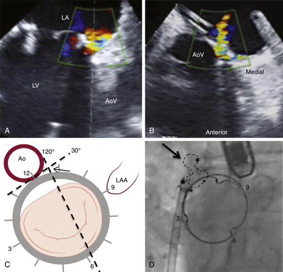
A, TEE 120-degree view, and B, TEE 30-degree short-axis view. C, The TEE planes are shown on the mitral valve clock face (LV view) with the intersection (arrow) defining the PVL origin. D, Deployment of the Amplatzer muscular ventricular septal defect (VSD) occluder (arrow) confirms the initial leak localization by TEE (left anterior oblique projection). AoV, aortic valve; LA, left atrium; LAA, left atrial appendage; LV, left ventricle.
Localization of Aortic Paravalvular Leak
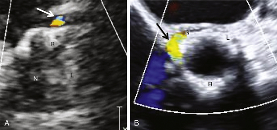
A, Transthoracic echocardiogram parasternal short-axis view, leak at native right coronary cusp. B, Transesophageal echocardiogram short-axis view (45°), leak at junction of right and noncoronary cusps. L, native left coronary cusp; N, native noncoronary cusp; R, native right coronary cusp.
Procedural Echocardiography
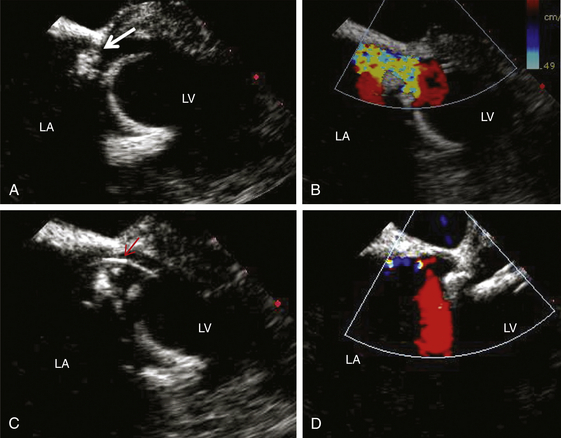
A, Two-dimensional view of the PVL (arrow). B, Color-flow Doppler demonstration of the leak. C, Wire across the leak (arrow). D, Minimal mitral regurgitation after deployment of closure device. LA, Left atrium; LV, left ventricle.
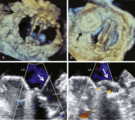
Three-dimensional TEE (LA view) shows the wire crossing the PVL (A) and the Amplatzer septal occluder device in position (partially in the left atrial appendage [LAA]) (B). C and D, Confirmation in two-dimensional TEE view. LA, Left atrium; LV, left ventricle.
Procedural Fluoroscopy and Angiography
Procedural Computed Tomography–Fluoroscopy Fusion Imaging

12.2 Techniques for Paravalvular Leak Closure
Access Site/Approach for Paravalvular Leak Closure
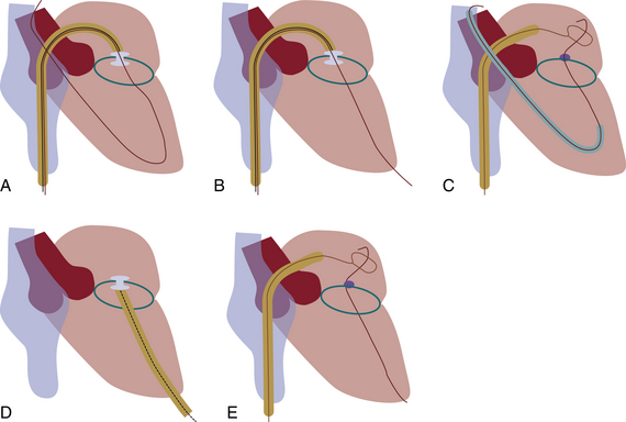
A, Antegrade wiring via transseptal (TS) puncture followed by advancement of the wire to the descending aorta. B, TS wire is snared via transapical (TA) puncture. C, Retrograde wiring from the left ventricle followed by TS puncture and delivery of devices via the antegrade TS approach. D, Retrograde wiring and device delivery via TA sheath. E, Retrograde wiring via TA approach followed by TS puncture to snare the wire and advance devices in an antegrade fashion. (Adapted from Kapadia, SR., Tuzcu, EM. Plugging holes. Circ Cardiovasc Interv 2011; 4: 308-10.)
![]()
Stay updated, free articles. Join our Telegram channel

Full access? Get Clinical Tree


Percutaneous Repair of Paravalvular Leaks

