THE CARDIOPULMONARY BYPASS CIRCUIT
The cardiopulmonary bypass (CPB) circuit is intended to isolate the cardiopulmonary system so that optimal surgical exposure can be obtained for operations on the heart, lungs and great vessels. For this isolation to be effective, the CPB circuit must be able to perform the functions of the intact cardiopulmonary system for a finite period. At a minimum, the circuit must be capable of adding oxygen and removing carbon dioxide from blood and of providing adequate perfusion of all organs with this blood. In addition, the circuit must be able to fulfill these requirements without doing permanent damage to the cardiopulmonary system, the blood, or any of the patient’s end organs.
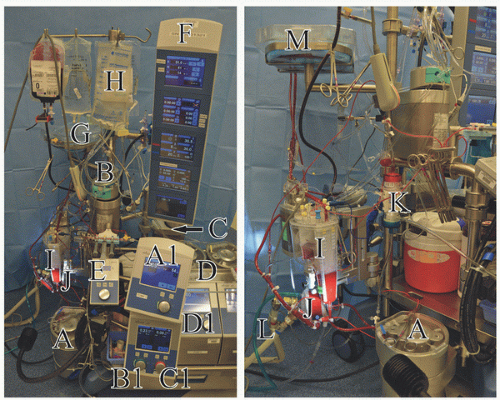
The major components for consideration in a pediatric bypass circuit are the arterial pump, oxygenator, venous reservoir and cardiotomy system, heat exchanger, arterial line filter (ALF), tubing, cannulas, and hemofilter (
Fig. 28.1). A cell saver can be regarded as accessory equipment.
Arterial Pump
The arterial pump system is the “heart” of the heart-lung machine, being the driving force to the “lung” of the heart-lung machine. Arterial pump head systems are classified as either
roller head or
centrifugal head. Most pediatric perfusion practices utilize a roller head for the arterial pump (
1).
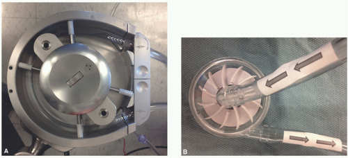
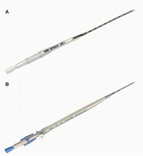
Roller Head Pump
The roller head pump, shown in
Figure 28.2A, consists of a raceway where two roller spindles oriented 180° from each other rotate around a central axis and compress the raceway tubing. This raceway tubing is also referred to as the “boot line.” The double-headed roller pump is a positive volume displacement pump. Sequential compression of the boot line propels the blood forward. The amount of compression of the tubing is set in a manner to ensure forward flow without
being over- or underocclusive, otherwise known as the minimally nonocclusive setting. This compression setting is simply referred to as the “occlusion” and is set during priming of the circuit. Proper occlusion is commonly set at a level that allows for the fluid level in the arterial limb to fall at a rate of 1 cm/min when held 75 cm above the venous reservoir fluid level. An overocclusive setting risks damaging the formed elements of the blood as well as increasing the risk of rupturing the boot line. An underocclusive setting risks damaging blood elements by allowing for sloshing in the raceway and compromises effective forward flow. This becomes an important safety issue if flow is not being monitored with an arterial line flow probe. Roller head pumps in modern heart-lung machines have the advantage of very low primes, since it is common for the arterial head to be positioned close to the venous reservoir and oxygenator. These pump heads also operate independently of vascular and system resistance, thereby allowing precise low-flow management, which is especially important in pediatric perfusion. To prevent circuit disruptions with load-independent roller head pumps, it is standard practice to incorporate servoregulating pressure monitoring to prevent excess system pressures. Circuit system pressure normally ranges between 100 and 250 mm Hg, but with kinked tubing or a misplaced line clamp can instantly spike to >500 mm Hg. Servoregulation adjusts arterial pump flow automatically to prevent pressures which could cause circuit connections to fail with subsequent loss of cardiopulmonary support.
Centrifugal Head Pump
The centrifugal head pump, shown in
Figure 28.2B, operates on the principle of a constrained vortex. Impellers or vanes on a spinning disc within plastic housing create negative pressure at the pump’s central axis inlet and positive displacement at the pump’s normally singular outlet, positioned at its outer circumference. As with roller head systems, a centrifugal head system is positioned in the bypass circuit to aspirate blood from the venous reservoir and to then pump it into the oxygenator. Centrifugal heads have the theoretical advantage of creating less trauma to the formed elements of the blood (
2,
3). However, a best-evidence review in patients undergoing elective coronary artery bypass grafting failed to find a significant difference in this regard as compared to roller head pumps (
4). Centrifugal heads are afterload-sensitive. An afterload-sensitive system greatly reduces the chances of overpressurizing a pump circuit that can lead to component and system failure, otherwise referred to as “blowing up a circuit” (
5). This benefit comes at the expense of less-constant pump flow when system resistance varies (changing systemic vascular resistance, pressure on the arterial limb of the circuit by the surgical team, cannula position change, etc.). Centrifugal heads also reduce the risk of massive arterial air embolism in the case of an emptied venous reservoir, because forward flow is stopped if large amounts of air enter the constrained vortex. Disadvantages of centrifugal systems relative to roller systems for pediatric perfusion include cost and increased prime volume. As with roller head pumps, it is standard practice to incorporate servoregulating arterial circuit pressure monitoring. Additionally, centrifugal systems commonly incorporate a one-way valve in the arterial limb of the bypass circuit to prevent retrograde flow back through the device which could occur during low-flow and no-flow conditions. Automated pump arterial line clamps which activate to prevent retrograde flow may also be used.
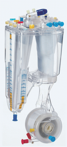
Oxygenators
Oxygenators perform the gas exchange functions of the lung and are thus the “lung” of the heart-lung machine. In modern systems, the oxygenator is integrated with several additional components, including the gas exchange membrane, venous reservoir and cardiotomy filter, and heat exchanger (
Fig. 28.3). Some oxygenators on the market are also integrated with an
ALF. Despite the fact that oxygenators are incorporated in a system in which blood is pumped under pressure, all gas exchange occurs at atmospheric pressure because the oxygenators are vented to the atmosphere.
Design
There are two distinct types of oxygenators: bubble oxygenators and membrane oxygenators. Bubble oxygenators will not be discussed here, because essentially only membrane oxygenators are currently used in the care of pediatric cardiac surgical patients (
6,
7).
Membrane oxygenators can be classified as either microporous or true membrane. The gas exchange membrane for pediatric CPB is nearly universally of the microporous type. Microporous membranes are made of 200 to 300 µm diameter polypropylene tubes with hydrophobic pores 0.03 to 0.07 µm in diameter. These pores cover at least 50% of the membrane surface. Blood flow is normally on the outside of the tubes, while countercurrent gas flow is through the inside of the tubes. This is referred to as extraluminal blood flow and is preferred over intraluminal flow, which has a higher risk of membrane clots and shunts which could quickly decrease device performance. Upon exposure to blood, the micropores are designed to become covered with a thin proteinaceous layer through which gas exchange occurs without blood and gas coming in direct contact.
The other type of membrane oxygenator is referred to as a true membrane or a solid membrane type because an intact membrane separates the gas and blood. Solid membranes are constructed of methyl silicon rubber that is thin enough (<25 µm) to permit diffusion of gas, with CO2 diffusing across the membrane five times as easily as O2. These membranes are more limiting to diffusion than microporous systems, and therefore require a greater gas exchange surface area. Hence, the priming volume to provide comparable gas exchange is larger. They also do not share the important advantage of microair removal from the blood flow path that microporous-type systems have. A major advantage of true membranes is that they have a useful life measured in days. For this reason, true membranes are still used in the setting of extracorporeal membrane oxygenation (ECMO), although their use in this setting is decreasing as advances in microporous systems have increased their useful life.
Gas Exchange
While modern membranes themselves offer little impedance to gas diffusion, there are other characteristics of membrane oxygenators that limit gas exchange. The primary determinants of O
2 and CO
2 exchange across a membrane are the solubility and diffusability of each in blood and the partial pressure gradient across the membrane. Because O
2 is less soluble and diffusible in blood than CO
2 (ratio of 1:25), the thickness of the blood film has a greater influence on oxygen exchange. Approximately 90% of the resistance to diffusion in a membrane oxygenator system is diffusion of O
2 into blood (
8). The pressure gradient for O
2 can be increased by increasing the O
2 concentration in the fresh gas flow. However, because of the lower diffusability of O
2, a thick blood film or boundary layer will result in poor O
2 delivery to the erythrocytes most distant from the gas exchange pores, even when the pressure gradient for O
2 is high. Modern membranes have design features to induce eddy currents, which serve to limit the boundary layer and maximize red blood cell exposure to the micropores. As CO
2 is more soluble and diffusible than O
2, CO
2 exchange is mainly dependent on the pressure gradient for CO
2 across the membrane. The rate of CO
2 removal can be increased by increasing the oxygenator’s sweep flow rate of ventilating gas, which is analogous to increasing alveolar ventilation. The rate of CO
2 removal can also be enhanced by decreasing the CO
2 content of the sweep gas. Most adult oxygenator systems do not contain CO
2 in the sweep gas but pediatric programs utilizing pH-stat blood gas management commonly do, and therefore CO
2 content of the ventilating gas becomes an important consideration.
Capabilities and Sizing
The properties of O2 transfer into and CO2 removal from the blood are defining characteristics of the different oxygenators. The manufacturing techniques for oxygenator bundle wrapping, the overall oxygenator membrane surface area, and the blood flow path through the device will primarily determine the gas transfer capabilities and maximum recommended blood flow rate which can be handled by the device. To note, over the course of several hours of use, the gas exchange capacity of microporous membranes deteriorates as a protein layer coats the micropores. The designed useful life for gas exchange in microporous oxygenators, as stated by their manufacturers, is normally 6 hours. Pediatric perfusion systems must appropriately size the oxygenator to meet the anticipated individual patient needs for gas exchange and blood flow.
Air Embolism
Microporous systems have been proven to be immensely effective. Because their efficient gas exchange properties and microair removal are difficult to match, they have lead the marketplace for cardiac surgery for more than two decades. A disadvantage of microporous membranes is that air can be drawn across the micropores into the blood flow path under unique negative pressure situations. Negative pressure in the oxygenator can occur at any time but practically speaking this can occur during or after bypass. On bypass, if there is an abrupt stoppage of blood flow, the fluid momentum in the oxygenator has the potential to pull ventilating gas into the blood flow path. Excessive suction while drawing blood samples, especially with low flow rates or regional perfusion, can draw ventilating gas into the blood flow path. After bypass, air can be drawn into the blood flow path during traditional
arteriovenous modified ultrafiltration (MUF). Postoxygenator ALFs are therefore extremely important safety devices.
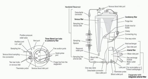
Venous Reservoir and Cardiotomy System
The venous reservoir and cardiotomy system are other components integrated into modern oxygenator systems (
Fig. 28.4). Integration of the venous and cardiotomy systems decreases prime volume and overall system surface area by eliminating separate connections between the two devices.
Venous Reservoir
The venous reservoir has blood flow into it directly from the bypass circuit venous line as well as from the cardiotomy filter. Venous return from the patient has its own dedicated filtration system to process the relatively clean venous blood. Venous reservoirs may be open or sealed. Open reservoirs are open to the atmosphere so that air is automatically purged. Sealed reservoirs have a single venting port which may be easily sealed for use with vacuum-assisted venous drainage (VAVD). VAVD requires the use of a sealed reservoir.
Cardiotomy System
Cardiotomy suction serves as an important source of blood conservation. Most systems use a roller pump to provide cardiotomy suction, with the collected blood directed to a cardiotomy filter that then drains into the venous reservoir. As the cardiotomy suction is frequently used during cannula placement before initiation of CPB, it is essential that adequate heparinization be achieved before use of cardiotomy suction so that clot does not form in the cardiotomy filter or venous reservoir.
The cardiotomy filter is normally located higher than and behind the venous reservoir. This superior arrangement allows the cardiotomy filter, which may have more dynamic volume hold up during filtering, the time necessary to work before blood drains into the circulating volume of the venous reservoir. Placing the cardiotomy filter posteriorly in the venous reservoir allows the perfusionist to visualize and focus on the forward facing venous reservoir level to constantly ensure a safe operating level.
The cardiotomy filter has a higher filtration capacity than the venous return filter to handle blood from the field suction devices and ventricular vent line. Cardiotomy blood always has air mixed in and may also contain particulate contaminants which necessitate increased filtering capacity. While cardiotomy suction has its disadvantages, most clinicians consider it obligate, especially in pediatric cardiac surgery, because of the volume of blood lost to the field with collateral circulations and general bleeding during the course of surgery. If cardiotomy suction was not used in these situations, there would be a regular need for homologous blood transfusion simply to maintain a sufficient volume within the CPB system. And, the loss of plasma via cell saver salvage may also be unacceptable.
Blood from the pericardial well collected by cardiotomy suction during bypass and returned to the venous reservoir is known to activate the extrinsic coagulation pathway (
9). This aspirated pericardial well blood contaminated by tissue contact is the most significant activator of the coagulation system
during bypass (
10). Pericardial aspirate is rich in tissue factor (TF) and procoagulant cellular (primarily platelet) derived microparticles (
10,
11,
12). It has also been demonstrated that elimination of cardiotomy suction return to the venous reservoir or washing of pericardial cardiotomy blood prior to return reduces inflammatory mediator generation and thrombin, neutrophil, and platelet activation (
13). Cardiotomy suction is the major source of blood trauma and hemolysis during CPB due to the unavoidable aspiration of air and blood (
10,
14).
In addition to cardiotomy suction, bypass circuits utilize a roller head pump to provide ventricular venting. The vent line collects blood from the ventricular vent and normally returns it to the cardiotomy filter.
HEAT EXCHANGER
Cardiopulmonary bypass commonly utilizes hypothermia to reduce systemic, especially cerebral, oxygen consumption and to aid in maintaining myocardial hypothermia during cardioplegic arrest. Heat exchangers are necessary to produce the active cooling and rewarming of the patient’s blood required for hypothermic bypass. Integration of the heat exchanger into the oxygenator system is a common way to reduce prime volume.
The oxygenator heat exchanger has a stainless steel or plastic barrier separating countercurrent flow of water and blood. A folded flat sheet design increases the surface area for heat transfer. The water temperature is controlled by a thermocirculator which is commonly referred to as a heater-cooler. The perfusionist sets the temperature of the water to effect the target patient temperature for various phases of bypass. This water temperature is set within certain limits outlined by the manufacturer. The temperature gradient between the venous blood inlet and the water inlet is normally kept less than 10°C. This maximum gradient helps evenly cool and warm the blood and patient while preventing gas from coming out of solution. Excessive gradients during warming or cooling can allow gas to come out of solution to form microemboli in the blood of the patient and bypass circuit. In other words, if cold blood with its higher gas solubility enters a warmer area of the patient or circuit with lower gas solubility, gaseous microemboli (GME) can form. The integrated heat exchanger is normally rated for performance based on the achieved heat transfer divided by the potential heat transfer. This performance factor can be quantified with the following equation:
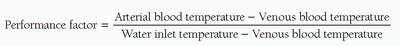
The performance factor will vary at different blood flow rates since the heat exchange surface area is fixed and heat exchange improves with time allowed for transfer. The adequacy of heat exchange performance is ideally considered at the maximum expected blood flow rate for a given cardiopulmonary bypass case. Of note, the water inlet temperature should never reach 40°C, as at 42°C protein denaturation and damage to the blood may result. Also, aggressive rewarming should be avoided since hyperthermic perfusate temperatures have been linked to greater neuropsychologic dysfunction after cardiac surgery (
15), and an oxygenator outlet temperature greater than 37°C has been correlated with acute kidney injury (
16). These potential complications must be considered in light of the fact that oxygenator temperature systems at normothermia may under report outlet values by 0.5°C or more (
17).
A variety of heater-cooler systems are available, and include the 3T Heater-Cooler System (Sorin Group, Milan, Italy), Hemotherm CE (Cincinnati Sub-Zero Medical, Cincinnati, OH), and heater-cooler unit HCU 40 (Maquet Getinge Group, Göteborg, Sweden). Circuits can supply temperature-controlled water to the oxygenator heat exchanger, the cardioplegia heat exchanger, and warming/cooling blankets. Some centers have used hot and cold water from institutional sources (“wall water”) which are then passed through a mixing valve to control CPB temperatures. Such systems are costly and rarely used in light of the efficient and more cost-effective heater-cooler systems available today.
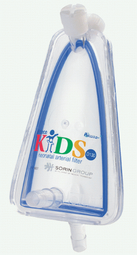
Arterial Line Filter
The ALF may be a separate (nonintegrated) component positioned distal to the oxygenator or less commonly integrated into the oxygenator.
Nonintegrated ALFs consist of a screen filter, usually made of polyester, which may be a flat sheet or folded and layered to increase contact surface area (
Fig. 28.5). This screen filter commonly has a pore size of 20 to 40 µm which traps particulate matter and air larger than its pore size. There is usually a low-flow purge of blood at the top of the device which returns blood, and any air, to the cardiotomy filter.
Integration of the ALF into the oxygenator is of particular benefit in pediatric cardiac surgery since a significant reduction in prime volume can be achieved. The integrated ALF is primarily wrapped around the oxygenator membrane, but can be integrated into the oxygenator bundle itself with unique bundle weaving technology. Neither of these designs requires a purge line to the cardiotomy filter. Wrapping the filter medium around the oxygenator bundle has the advantage of creating back pressure which can purge microair into the gas flow path of the microporous oxygenator. The other method for integrating the ALF with the oxygenator is by constructing the oxygenator bundle fibers such that the space between the membrane fibers before the blood exits the device is a maximum of 25 to 40 µm. There is currently only one oxygenator on the US market which is approved with this technology (Affinity Fusion Oxygenation System, Medtronic, Minneapolis, MN), and it is unclear if this technology will become more prevalent in future devices. Studies comparing the effectiveness of GME removal by available external ALFs to integrated filters wrapped around the oxygenator bundle and filtration provided by unique bundle
wrapping technology are warranted to validate these relatively new technologies.
Tubing
Custom tubing packs are an essential item for pediatric perfusion practice. The overall goals for tubing selection are to minimize sizes and requisite prime volume while assuring reasonable system pressure so as not to damage the blood or increase the risk of tubing disconnect while on bypass. Tubing packs can be customized to accommodate an institution’s selection of heart-lung machine and arterial head systems, oxygenators, ALFs, and the positioning of these components relative to the surgical field.
Tubing Sizes
Tubing sizes for congenital heart surgery range in internal diameter sizes from 1/8 to ½ inches, and will vary within each custom set-up. Prime volumes for different size tubing are shown in
Table 28.2.
Institutions generally have accepted maximum values for system pressure and achievable flow rates for the different tubing sizes. Tubing packs are then defined based on anticipated pump flow and line lengths required within a CPB setup. For example, a program may start with 3/16-inch tubing for the major tubing components (arterial and venous limbs, boot line) for patients with an expected maximum bypass flow rate of 600 mL/min. As patient weight and expected flow rates increase, the different tubing components are then upsized. The venous limb size is normally increased first, followed by the boot line, and finally the arterial limb until adult bypass circuit sizes are achieved. An adult circuit commonly has a 3/8-inch arterial limb with ½-inch venous and boot lines. The venous limb tends to be the largest tubing prime component, but can be reduced in size with augmented venous return (kinetic and vacuum assisted drainage) techniques.
Table 28.3 provides an example of tubing selection based on its position and maximum recommended pump flow rate.
The left ventricular and other vent lines and the field suction lines are other primary components of a custom tubing pack. They are not normally primed before bypass and so their volumes have less impact on the system. However, their sizing is particularly important for small patients because they can be intermittently primed with blood during bypass. Generally, these lines are primed at various times during bypass, but are free of blood during the weaning phase of bypass. For example, an aortic root vent line may be primed with aortic root blood after aortic cross-clamping and during rewarming to aid in de-airing. This line is then either disconnected or
allowed to deprime to the bypass circuit before separation from bypass.
Surface Modification
Treatment of the bypass circuit tubing, cannulas, and oxygenators with heparin and other surface-modifying agents (SMAs) has been undertaken by manufacturers in an effort to increase the circuit’s biocompatibility (
18,
19,
20). In theory, use of SMAs should result in decreased activation of platelets and attenuation of the inflammatory response induced by contact activation (
21). However, solid evidence linking use of SMAs to meaningful improvements in important clinical outcomes such as reduced blood loss, reduced incidence of renal dysfunction, or shorter duration of ventilatory support in either children or adults undergoing cardiac surgery with CPB is lacking (
21,
22). Despite this, SMAs are clearly in widespread use in pediatric cardiac surgery programs; a 2011 review of international pediatric perfusion practice reported that 85% of programs were using CPB circuits that incorporated SMAs (
1,
7).
Cannulas
Once the circuit components for bypass are selected and assembled, and the circuit primed, attention shifts to cannulation. Assuring proper arterial inflow and venous outflow with appropriate gas exchange are important first assessments when placing a patient on CPB. This includes not only the type and size of the arterial and venous cannulas, but also the site for cannulation.
Arterial Cannulas
Arterial inflow is provided most often with a single arterial cannula placed in the ascending aorta proximal to the innominate artery. Alternative arterial inflow strategies include femoral arterial cannulation for reoperations, double arterial cannulation for interrupted aortic arches, and ductus arteriosus/pulmonary artery cannulation for ascending aorta and aortic arch hypoplasia. The surgeon must be cognizant of the arterial cannulation strategy required and its potential effects on systemic perfusion, operative strategy and blood pressure monitoring sites.
Sizing of arterial cannulas is by their outer diameter. The lumen must be large enough to allow for anticipated pump flow rates while not creating excessively high system pressures. If a cannula is too large, it can obstruct native heart output, particularly in the ascending aortic position as this output is critical during cannulation and the initiation and weaning phases of bypass. An arterial cannula that is too small, in addition to limiting flow, leads to high pressures, increased flow velocities, jetting against the arterial wall, and high shear forces which may damage the formed elements of the blood (
23,
24). The pressure drop across an arterial cannula is normally limited to 100 mm Hg. Arterial cannulas come in a variety of styles and sizes to meet the varied needs of congenital cardiac patients (
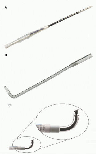
Fig. 28.6). The outer diameter for arterial cannulas ranges from 6 to 24F to accommodate neonates to older adults. Arterial cannulas commonly have wire-wound bodies to resist kinking. Additionally, arterial cannulas should not become too rigid during hypothermia since this can put undue stress on the aortic wall.
Venous Cannulas
The venous limb of the bypass circuit connects to the venous cannulas. The majority of adult cardiac procedures are extra-cardiac in nature (coronary artery bypass grafts and aortic valve replacements) and may be performed with only a single right atrial cannula for venous drainage. In contrast, most congenital heart operations are intra-cardiac. Venous drainage is typically provided with bicaval cannulation, which allows for total CPB. Venous cannulas are normally rated for achievable flow based on the pressure drop across their length in the setting of gravity siphon drainage (GSD). A pressure drop less than 35-40 mm Hg is commonly used as a limit. Venous cannulas ideally have an internal lumen that is large enough to handle the expected portion of the bypass flow diverted to it while not having an external diameter that completely occludes the vessel. Venous cannulas commonly have side port holes, in addition to the tip hole, which importantly affect flow performance. Blocking these side ports by inserting too large a cannula can diminish flow performance and desired flow rates (
Fig. 28.7). It follows that a maximized internal-to-outer (IO) ratio of cannula diameter is advantageous. For this reason, metal- and hard plastic-tipped venous cannulas are commonly used in pediatric settings. These materials lend
themselves to more favorable IO ratios than standard cannula materials such as polyvinylchloride.
Hemofilters
Hemofilters are devices commonly added to the CPB circuit to filter blood by removing water, low molecular weight solutes (potassium, glucose, heparin, citrate, lactate), and inflammatory mediators (
25,
26). The removal of water results in hemoconcentration and an increase in the hematocrit. These devices produce the ultrafiltrate as a result of a hydrostatic pressure gradient across a semipermeable membrane, and are the same devices used for hemodialysis. When hemofilters are used in conjunction with CPB, they are commonly called hemoconcentrators. Use of the term “ultrafilter” is commonly used without distinction.
Hemofilters consist of a core of microporous hollow fibers made of polysulfone, polyethersulfone, polyamide, or polyacrylonitrile material arranged in a bundle. The pore size in hemofilters generally allows molecules less than 60,000 to 70,000 Da to pass. Due to the pressure drop across the device, blood inflow can either be passively obtained from the arterial side of the CPB circuit or actively provided with the use of a roller head pump. Hemoconcentrator outflow is normally diverted to the cardiotomy venous reservoir. The ultrafiltrate is collected in a container, commonly connected to a regulated vacuum source, and discarded.
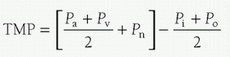
The ultrafiltrate has the composition of glomerular filtrate, and the rate at which it is produced is dependent on the transmembrane pressure (TMP). TMP is determined by the arterial inlet pressure (Pa), the venous outlet pressure (Pv), the absolute value of applied suction at the outlet (Pn), the oncotic pressure at the inlet (Pi), and the oncotic pressure at the outlet (Po), as follows:
Using the regulated vacuum source connected to the outlet of the device increases or decreases Pn. For most hemofilters, the TMP should not exceed 500 mm Hg.
The techniques and potential benefits and risks of ultrafiltration are discussed later in the chapter in the section relating to the conduct of CPB.
CARDIOPULMONARY BYPASS CIRCUIT PRIME
The prime volume of the bypass circuit is a simple function of adding the prime volume of the various components utilized. Normally, the lowest volume circuit components available which can safely provide the anticipated maximum flow rates and gas exchange, with some performance reserve, are chosen. The circuit is commonly flushed with CO2 and then primed with a crystalloid solution. This process helps ensure that the components of the circuit and their connections are not leaking and are visually free of air. Thereafter, the degree of hemodilution (dilutional hematocrit, %) is calculated using the following formula:
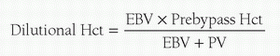
where EBV = the patient’s estimated blood volume (mL) and PV = circuit prime volume (mL). The patient’s EBV is the product of weight and blood volume. Because blood volume changes with weight/age, EBV is calculated using the values shown in
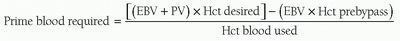
Table 28.4. If the dilutional hematocrit is deemed acceptable, the prime can be buffered and the patient can be placed on CPB with a clear prime. If the dilutional hematocrit is deemed too low, red blood cells may be added to the circuit to achieve the desired dilutional hematocrit. The amount of blood required (mL) in the circuit prime can be calculated with the following equation:
Institutional practice varies with respect to the type of blood used (packed red blood cells with or without plasma added) for priming the circuit and the lowest acceptable dilutional hematocrit. While most centers use packed red blood cells, the use of whole blood or packed red blood cells reconstituted with plasma may reduce untoward dilution of clotting factors during bypass (
27). A safe dilutional hematocrit for CPB has yet to be defined for the numerous cardiac defects seen in pediatric cardiac surgery. Analysis of the Boston hemodilution trials found that in neonates and infants undergoing biventricular repair without arch reconstruction, a hematocrit greater than approximately 24% on bypass was associated with improved neurodevelopmental outcomes (
28). While there has been great interest in transfusion-free bypass for congenital heart surgery, studies are needed to demonstrate that lower hematocrit strategies have comparable neurologic outcomes as compared to protocols maintaining a hematocrit greater than 24% during CPB in pediatric cardiac surgery patients. The current practice at Boston Children’s Hospital is a dilutional hematocrit at the onset of bypass of 24% to 35% in neonates, infants, and children and depends on the underlying diagnosis and intended operation.
CONDUCT OF CARDIOPULMONARY BYPASS
Initiation of Bypass
In clinical practice, the perfusionist initiates bypass by releasing the circuit arterial limb clamp and increasing pump flow to the arterial cannula. It is imperative that the circuit system pressure is within acceptable and expected limits as flow is increased toward the target rate. An excessively high pressure indicates a problem ranging from a simple failure to remove the arterial limb clamp or a kinked arterial limb to a malpositioned cannula or ascending aortic dissection. The surgeon and perfusionist must be familiar with how to deal with these events. The circuit venous limb clamp is released after the arterial limb clamp but it is held near the venous line until proper venous drainage and arterial inflow are reasonably assured. Reapplication of the venous clamp may be necessary to prevent exsanguination if the arterial cannula inadvertently comes out or if arterial inflow is interrupted in some other way during this critical phase of bypass. Preventing exsanguination significantly decreases emergent interventions required when arterial inflow is compromised and being rectified during the initiation of bypass.
The assessment of venous drainage at the initiation of bypass is critical and is nearly simultaneous with assessment of arterial inflow. Proper drainage with the given venous cannulas normally equates to arterial inflow at its target rate with a sufficient and stable venous reservoir volume. If this is not the case, several considerations must be made including adjustment of cannula position and/or size and verification of bypass circuit venous limb patency. Initiation of bypass is almost always with GSD, commonly referred to as “gravity.” Gravity drainage for bypass is dependent on venous cannula size, the relative height of the patient above the venous reservoir, the length and diameters of the venous tubing, maintenance of a continuous fluid column, characteristics of the venous reservoir, and patient volume status (
29). These requirements can be limiting with the small cannulas and bypass tubing used in pediatrics and a problem when significant collateral or other unique circulations flood the surgical field preventing adequate visualization for the surgeon. These concerns and the desire to decrease prime volume have led to an increased use of augmented venous return strategies for pediatric CPB.
Most commonly in pediatric perfusion, augmented venous return is via vacuum-assisted venous drainage (VAVD). The vacuum technique has the perfusionist apply negative pressure from a regulated vacuum source to a sealed hard-shell venous reservoir. This vacuum pressure gets transmitted to the venous limb of the bypass circuit. The requirements of gravity drainage described above become less important with use of VAVD. Vacuum can improve drainage and visualization at the field. Vacuum assisted drainage is not without risk. Vacuum increases air entrainment into the venous limb of the circuit that, even with arterial line filtration, has been shown to increase arterial line GME transmission to the patient (
30,
31,
32,
33). It is unclear what level of GME becomes associated with adverse neurologic outcomes, but even the proper application of vacuum assist has been associated with a devastating outcome (
34). VAVD also carries an increased risk of massive air embolism via the venous limb of the bypass circuit due to the venous reservoir being sealed and the presence of a nonfunctioning high-pressure relief valve (
35,
36,
37). Vacuum drainage can greatly aid the surgeon and decrease circuit prime volume and decrease transfusion requirements for bypass (
38). Proper clinical application of VAVD has the potential to prevent untoward outcomes (
39) but much research is needed to qualify the effect of increased GME load on clinical outcome in congenital cardiac surgery. An alternative technique to VAVD is kinetic-assisted venous drainage (KAVD). With KAVD, a kinetic pump applies suction to the venous drainage
line rather than to the reservoir. A centrifugal pump is used for control of the negative pressure (
24).
Once proper arterial inflow and venous drainage are assured, bypass parameters are adjusted to achieve target flow rates, mean arterial pressure, depth of hypothermia, and blood gas values.
Partial versus Total Bypass
The initial phase of bypass is usually partial CPB. With partial CPB, only a portion of the systemic venous return to the heart drains into the bypass circuit, with the remaining portion passing to the right atrium (RA). Ideally, right atrial return passes to the right ventricle (RV) and pulmonary vasculature, where gas exchange occurs. The blood then returns to the left atrium (LA) and left ventricle (LV), from which it is ejected into the systemic circulation. During partial CPB, the patient’s systemic blood flow is therefore provided in part by the CPB circuit and in part by the patient’s heart. There are two essential requirements for partial bypass to be effective: the heart must be beating and ejecting and the lungs must be ventilated. If ejection is ineffective or nonexistent, distention of the heart will occur and systemic blood flow will be inadequate. In the absence of ventilation, pulmonary venous blood returning to the LA will ultimately reach the systemic circulation without having undergone gas exchange; this can result in hypoxemia and hypercarbia. The patient’s arterial Po2, Pco2, and pH are thus a reflection of the quantity and effectiveness of gas exchange in the two sources of systemic blood flow. Therefore, during partial CPB, samples for blood gas analysis must be drawn from the patient and not from the CPB circuit in order to accurately reflect in vivo conditions.
Cases with single venous cannulation of the right atrium effectively have the patient on partial bypass. In contrast, if nearly all of the venous return is diverted to the CPB circuit, the patient is said to be on total CPB. Total bypass is normally achieved with bicaval cannulation and caval snares, which prevent blood from circumventing the caval cannulas. Caval snares also prevent air from entering the bypass circuit once the right heart is opened. Total bypass is preferred for intra-cardiac repairs to aid in visualization at the surgical field. Capturing all venous return to provide true total bypass in congenital cardiac patients can be problematic. Patients may have a persistent left superior vena cava (SVC) with drainage to the coronary sinus, an interrupted inferior vena cava (IVC) with drainage of hepatic veins directly to the RA or azygous continuation to a left-sided SVC, which may not be easily accessed or cannulated. These situations usually require increased use of field suction in the pericardial well or in the heart itself.
Flow Rates and Temperature
Flow rates during CPB are chosen to provide adequate systemic oxygen delivery. Systemic hypothermia is routinely employed during pediatric CPB, with many operations performed at temperatures of 28°C to 32°C. Systemic hypothermia reduces whole-body and cerebral oxygen consumption 5% to 7% for each 1°C decrease in body temperature (
40). Flows of 1.8 to 2.5 L/min/m
2 are commonly used for infants, children, and adults during mild-to-moderate systemic hypothermia. Due to age-related differences in the relationship of weight to body surface area, when these flow rates are expressed in mL/kg/min, they will be substantially higher in the neonate than in the adult. Low-flow CPB in neonates and infants is conducted at temperatures of 18°C to 22°C and flow rates of 50 to 75 mL/kg/min or approximately 0.7 to 1.2 L/min/m
2. The arterial pump head output is decreased from the full flow value in a temperature appropriate fashion.
Table 28.5 lists common index flows used in pediatric CPB relative to patient temperature. These listed flows are general estimates only as flow rates vary with surgical and patient needs. Near infrared spectroscopy (NIRS) monitoring of regional cerebral tissue oxygen saturation is used by clinicians as an adjunct to real-time arterial and venous blood gas values in an attempt to provide safer blood flow rates during CPB (
41,
42,
43).
Blood Gas Management
Blood gas management during hypothermic CPB is a confusing and poorly understood topic for many clinicians new to cardiac surgery, and has been reviewed in detail by Jonas (
44). The best way to approach this subject is to understand 1) the change in pH of water and blood when cooled; 2) how blood gas analyzers function with respect to temperature; 3) the difference between the a-stat and pH-stat strategies with respect to how arterial blood gases are interpreted and whether CO
2 is added to the circuit ventilating gas; 4) cerebral autoregulation and the interaction with temperature
and pH; and finally (
5) α-stat and pH-stat in relation to the dominant mechanism of cerebral injury in pediatric cardiac surgery.
Change in pH of Water and Blood with Cooling
Electrochemical neutrality occurs when there are equal concentrations of hydrogen (H+) and hydroxyl (OH–) ions. Electrochemical neutrality is important for maintenance of a constant transcellular H+ gradient necessary for many cellular processes and optimal protein and enzyme function. In humans, electrochemical neutrality (ratio of H+:OH– = 1) occurs at an intracellular pH of 7.1, which is close to the pH of neutrality of water (7.0). Buffer systems maintain the extracellular pH at 7.4 and the intracellular pH at 7.1. The imidazole group of the amino acid histidine is present in many cellular and plasma proteins, including hemoglobin. Together with phosphate (mainly intracellular) and bicarbonate, these buffers maintain an equal concentration of H+ and OH– ions, and thereby electrochemical neutrality.
When water (and blood) is cooled, the dissociation constant (pK) decreases, resulting in an equal reduction in the concentration of H
+ and OH
– ions. As pH is the inverse logarithm of the H
+ concentration, and because the H
+ concentration decreases with cooling, the pH of the water (and blood) will increase. For each 1°C decrease in temperature, the pH of water will increase by 0.017 and the pH of blood will increase by 0.0147 (
45).
Changes in cellular pH during hypothermia are mediated through Paco2 homeostasis. As temperature decreases, the solubility of CO2 in blood increases. If the total CO2 content of blood is held constant, this increase in CO2 solubility will result in a reduction in Pco2. For example, if the total CO2 content is held constant and the measured Pco2 at 37°C is 40 mm Hg, then the measured Pco2 at 20°C will be 16 mm Hg. This causes pH to increase as temperature decreases and electrochemical neutrality is maintained.
Blood Gas Analyzers and Temperature
Blood gas analyzers evaluate samples at a temperature of 37°C. If a blood sample is lower than 37°C, the analyzer will warm the sample to 37°C and then measure the various parameters. Therefore, when a blood gas sample is drawn from a hypothermic patient and sent to the blood gas laboratory, the sample is warmed to 37°C before measurement. The values obtained at 37°C are called the temperature-uncorrected values. These values are then converted to temperature-corrected values at the patient’s temperature using a nomogram. The nomogram accounts for temperature-induced changes in pH, O2 solubility, and CO2 solubility in a closed-blood system. When pH and Paco2 are measured at 37°C and then corrected to a lower temperature, the electrochemically neutral pH will be higher and the corrected Paco2 will be lower than the values at 37°C. Temperature correction of blood gas values is independent of whatever blood gas strategy is being used to manage the patient and is only accounting for the physiochemical changes of temperature on pH and solubility of CO2 and O2.
α-Stat and pH-Stat
α-Stat and pH-stat are methods of acid-base management and directly influence blood flow to the brain and other organs.
In α
-stat regulation, electrochemical neutrality is maintained at whatever temperature the patient is at. This is achieved by allowing the pH to increase as the patient is cooled. The pH will be alkalotic and the Paco
2 decreased in the temperature-corrected blood gas and normal in the temperature-uncorrected blood gas. For example, when a blood gas is taken from a patient at 27°C, the temperature uncorrected (at 37°C) pH and Paco
2 will be 7.4 and 40 mm Hg, respectively, while the temperature corrected (27°C) pH and Paco
2 will be 7.55 and 26 mm Hg, respectively (
Table 28.6). With a-stat management, the total CO
2 content of the patient and bypass circuit is held constant.
With
pH-stat regulation, electrochemical neutrality is lost in that the pH is maintained at 7.4 and the Paco
2 at 40 mm Hg at whatever colder temperature the patient is at, that is, normal values on the temperature-corrected blood gas. As shown in
Table 28.6, at temperature-uncorrected values the pH will be acidotic and the Paco
2 higher than normal. A pH-stat strategy is achieved by adding CO
2 to the ventilating gas during hypothermic CPB to increase Paco
2 and decrease the pH. In contrast to a-stat regulation, in which total CO
2 content is kept constant, pH stat regulation results in an increase in total CO
2 content.
It is important to point out that at a patient temperature above 30°C there is essentially no difference between a-stat and pH-stat management. The difference between these strategies becomes more marked as temperature progressively decreases and is not clinically relevant until patient temperature is below 30°C. For practical purposes, it is easier to use uncorrected blood gases aiming for a pH of 7.4 and a Paco2 of 40 mm Hg at 37°C during a-stat management and blood gases corrected for patient temperature aiming for a pH of 7.4 and a Paco2 of 40 mm Hg during pH-stat management.
Cerebral Autoregulation, Temperature, and Metabolism
Landmark studies by Greeley and colleagues found that when a-stat regulation is used, pressure-flow autoregulation is preserved during moderate hypothermic (25°C-32°C) bypass, but is lost or attenuated during deep hypothermic (18°C-22°C) bypass (
46,
47). Cerebral blood flow (CBF) and cerebral O
2 consumption (CMRo
2) are appropriately coupled with a-stat regulation. In contrast, the addition of CO
2 during pH-stat management produces loss of autoregulation and uncoupling of CBF and CMRo
2 (
48). As a result, CBF varies linearly with arterial blood pressure and luxuriant cerebral blood flow exists with CBF far in excess of that dictated by cerebral metabolic rate. This hyper-perfusion state is the result of reduced CMRo
2 induced by hypothermia and cerebral vasodilation resulting from a disproportionately high Paco
2 for the degree of hypothermia present. Cerebral metabolism is exponentially related to temperature, and the temperature coefficient in neonates, infants, and children is 3.65 versus 2.4 in adults (
49,
50).
pH-Stat for Pediatric Bypass
The etiology of brain injury during CPB is a major consideration in the decision to use an α-stat or pH-stat strategy. Because of atherosclerotic disease, adults are more susceptible than children to brain injury resulting from macro- and microembolism of atherosclerotic debris. By linking CBF with CMRo
2 and thereby avoiding the cerebral hyperperfusion associated with pH-stat, α-stat regulation is most commonly used for adult cardiac surgery. Global and regional hypoperfusion is a bigger concern in the pediatric population. Additionally, lower temperatures, with shift of the oxyhemoglobin dissociation curve to the left, are more frequently required in children. Consequently, pediatric CPB more frequently uses the pH-stat strategy. Additional benefits of pH-stat include suppression of CMRo
2, which may prolong oxygen availability during periods of circulatory arrest, and more efficient brain cooling (
51). The acidosis associated with pH-stat increases the pulmonary vascular resistance and thereby decreases pulmonary blood flow, which has the benefit of reducing the steal of blood from the systemic and hence cerebral circulation in patients with significant aortopulmonary collaterals (
52). For an extensive review supporting the use of pH-stat in pediatric cardiac surgery, the reader is referred to reference (
44).