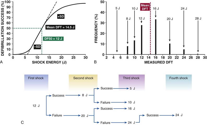
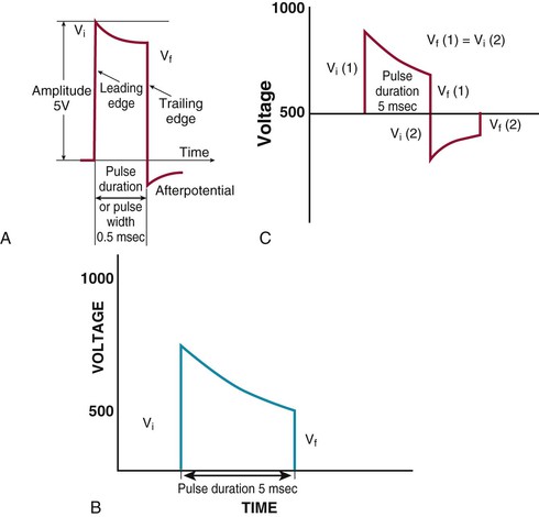
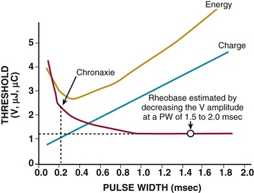
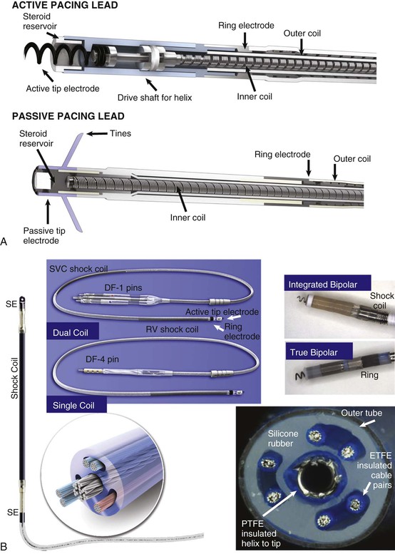
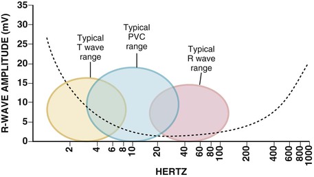
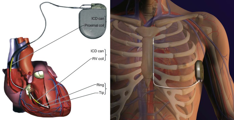
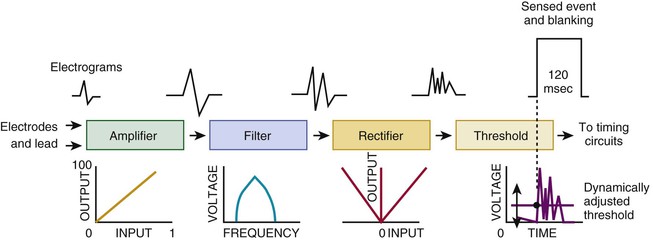
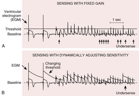
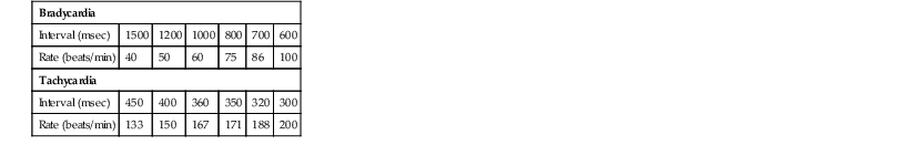
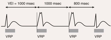
Charles D. Swerdlow, Paul J. Wang, Douglas P. Zipes Electrical therapy for cardiac arrhythmias includes low-voltage pacing pulses, which are used to treat bradycardia or to provide antitachycardia pacing (ATP) for termination of reentrant tachycardias, and high-voltage shock pulses, which are used to defibrillate atrial fibrillation (AF) or ventricular fibrillation (VF) or to cardiovert ventricular tachycardia (VT). An applied electrical stimulus interacts with cardiac electrical activity via its resultant electrical field, which is proportional to the spatial derivative of the voltage applied (local rate of change with respect to the distance derivative). The response of the heart is mediated by the passive and active (ion channel) properties of cell membranes, by the properties of electrical connections between cardiac cells, and possibly by direct intracellular electrical effects. Local and Global Effects of Cardiac Electrical Stimulation Cardiac pacing requires a local stimulus sufficient to depolarize (reduce the membrane potential of) local myocardium during diastole and initiate a self-propagating wave front of depolarization. To achieve this local effect, pacing pulses are delivered from electrodes with small surface areas (1 to 6 mm2). The local field strength required is approximately 1 V/cm. A stimulus that successfully stimulates local myocardium is said to capture it. Bradycardia pacing requires that the stimulus capture fully excitable local myocardium during diastole. The stimulated wavefront then propagates to most or all of the myocardium, which is also fully excitable, thereby resulting in electrical depolarization of cells and resultant mechanical contraction. In contrast, ATP stimuli must interact with the specific reentrant circuit driving the tachycardia, which is generally remote from the site of pacing, and it must do so while most of the myocardium is refractory or relatively refractory. Thus the ATP stimulus must capture local myocardium during the relative refractory period, propagate to the reentry circuit through relatively refractory myocardium, enter the circuit during an excitable gap in refractoriness, and terminate the tachycardia by causing a bidirectional block (see Chapter 33). Stimulus strength for local capture by ATP is higher than that for bradycardia pacing because ATP pulses are usually delivered to myocardium that is relatively refractory rather than fully excitable. Global. In contrast to pacing, initiation and termination of AF or VF by shocks require global field effects. Defibrillation shocks are delivered from electrodes with large surface areas (400 to 800 mm2 for transvenous electrodes, 35 to 70 cm2 for subcutaneous or epicardial electrodes, and 75 to 100 cm2 for transthoracic electrodes/patches) separated by 10 to 40 cm. The minimum global field strength required for ventricular defibrillation is 3 to 4 V/cm when using biphasic shocks and 5 to 6 V/cm when using monophasic shocks. Although the field strength required for defibrillation is only a few multiples of that needed for pacing, defibrillation requires that these field strengths be achieved throughout all (or almost all) of the ventricular myocardium, whereas pacing requires achieving it only locally, within a few millimeters of the tip electrode. This spatial difference in field requirements alone requires that defibrillation pulses contain approximately a million times as much energy as a pacing pulse. Additionally, the cardiac time constant (see later) is approximately 10 times longer for defibrillation than for pacing. Combining these two considerations, defibrillation pulses require approximately 10 million times more energy than pacing pulses do. Principles of Bioelectrical Stimulation Thresholds for Pacing and Defibrillation. A threshold stimulus is the minimum stimulus required to evoke a response. Stimuli weaker than the threshold never evoke a response, and stimuli stronger than the threshold always evoke a response. Thus the threshold for pacing is the minimum stimulus strength needed to depolarize local myocardium and to initiate a propagated response. Defibrillation is best described by a probability-of-success curve (Fig. 36-1A) rather than by a threshold.1 Shock strength is plotted on the abscissa and probability of successful defibrillation on the ordinate. Because defibrillation is probabilistic, the same clinically relevant shock strength may either succeed or fail on successive attempts. Nevertheless, the term defibrillation threshold (DFT) is used as the minimum shock strength that results in defibrillation during testing. DFT testing refers to various methods that assess the efficacy of defibrillation by calculating a shock strength on the sloping portion of the curve based on successes and failures of a few shocks at different strengths. Thus these methods are based on limited, discrete sampling of a continuous statistical distribution (Fig. 36-1B). Because repeated sampling of a probability distribution is likely to result in variations, repeated measurements of the DFT result in variation in measured values. Waveforms. The waveform of an electrical pulse is the temporal pattern of its amplitude, measured by voltage (or current). Voltage is a critical parameter for pacing or defibrillation because it determines the electrical field that interacts with the heart. In general, current is linearly related to voltage by Ohm’s law (V = IR, where V is voltage, I is current, and R is resistance). Waveform duration is critical because a pacing pulse or shock interacts with the heart for the duration of the waveform. Furthermore, the time course of the heart’s response to a pacing or defibrillation pulse depends on time-dependent passive and active ion channel processes, collectively referred to as the membrane time constant (τm) of cardiac tissue (see Chapter 33). Thus the most easily measured electrical parameter relevant to pacing or defibrillation is voltage (or current) as a function of time. Although implantable cardioverter-defibrillator (ICD) shocks are often specified in terms of energy (joules), energy is not a direct determinant of defibrillation. All pacing and defibrillation in implantable devices result from discharge of a capacitor. Thus they have a fixed leading-edge voltage and a trailing-edge voltage determined by the waveform duration and waveform time constant τw, which is defined as the product of the capacitance (C) and electrical resistance (R) of the pacing or defibrillation pathway (electrodes and tissue, τw = RC). τw is the duration in which the capacitor delivers 86% of its stored energy. Because pacing waveforms are short pulses delivered through high-resistance pathways, they approximate constant-voltage pulses with a lower amplitude, longer duration after potentials of opposite polarity (Fig. e36-1A Strength-Duration Relationship. A plot of the stimulus strength required for pacing or the shock strength required for defibrillation as a function of pulse duration is known as a strength-duration curve (Fig. 36-2). The strength-duration curve can be approximated by an inverse exponential or hyperbolic function. The strength-duration curve is characterized by two parameters. The rheobase is the long-duration asymptote (essentially the lowest value), which is determined by properties of the lead system and electrode-myocardial interface. The chronaxie is the duration at which the threshold is twice the rheobase amplitude. It may be considered an approximation of an aggregate membrane time constant for the myocardium. Clinically, the chronaxie is important for design of efficient pacemakers and ICDs because it relates to the waveform that paces or defibrillates with the lowest energy, and minimizing the energy required is an important consideration for the longevity and size of pacemaker and ICD generators. A waveform with a duration approximately equal to the chronaxie paces with the lowest energy. Presently, no comprehensive theory permits determining the waveform duration that defibrillates with lowest energy from first principles, but approximations and empiric data relate it to the chronaxie. For capacitive-discharge defibrillation waveforms, the duration (of the first phase of a biphasic waveform) that defibrillates with minimum energy may be considered intermediate between the optimal duration for response of the cell membrane (chronaxie or τm) and the optimal duration for the capacitor to deliver its charge (τw). Usually, τw exceeds τm, so phase 1 of transvenous biphasic waveforms exceeds the chronaxie by 25% to 75%. Programming Strength, Duration, and Polarity of Pacing and Defibrillation Pulses. The durations of pacing and defibrillation pulses are optimized to achieve the desired physiologic result with the minimum energy consumption from the device’s battery. Typically, the voltage output for pacing is set at 1.5 to 2 times the threshold at pulse durations of 0.4 to 0.5 millisecond and at 1.5 to 2 times the pacing chronaxie of 0.2 to 0.3 millisecond. Lower safety margins may be programmed for pacemakers that determine capture automatically on a beat-to-beat basis. The shock strength for defibrillation is typically programmed near the ICD’s maximum output of 750 to 900 V or 30 to 40 J with pulse durations of 3.5 to 6 milliseconds for the first phase of biphasic waveforms, longer than the defibrillation chronaxie of about 3 milliseconds but toward the short end of the range that permits the ICD to deliver the energy stored on the high-voltage capacitor. At the long coupling intervals used for bradycardia pacing, the pacing threshold is lower if the negative electrode (cathode) is used for stimulation, but at short coupling intervals, which may initiate tachyarrhythmias, the stimulation threshold is lower for the positive electrode (anode). Thus cathodal pacing is preferred for bradycardia pacing to enhance the device’s longevity and to minimize proarrhythmia. Anodal stimulation of the right ventricular defibrillation electrode is preferred for defibrillation, although polarity has little effect on the efficacy of defibrillation for presently used biphasic defibrillation waveforms. Metabolic Effects on Pacing and Defibrillation Thresholds. The most clinically important metabolic abnormality is hyperkalemia, which raises pacing and defibrillation thresholds and alters sensing by causing conduction delays and local conduction block. Additionally, marked acidosis or alkalosis raises pacing thresholds but does not affect defibrillation thresholds. Profound hypothyroidism can also raise the pacing threshold. Intracardiac Electrogram An electrogram (EGM) displays the electrical potential difference between two points in space over time. The electrocardiogram (ECG), recorded from two electrodes on the body’s surface, records electrical activity from the entire heart. In contrast, EGMs recorded from small endocardial or epicardial pacing electrodes record only local activity. Because EGMs record a difference in potential between two points, two electrodes are always required. However, in common use, the terms unipolar and bipolar refer to the number of intracardiac electrodes in the recording electrode pair. Unipolar EGMs are recorded between an electrode in the heart and a remote electrode, whereas bipolar EGMs are recorded between two intracardiac electrodes. Corresponding unipolar and bipolar terminology is applied to the electrodes used for pacing. Unipolar EGMs are recorded between a small tip electrode in the heart and a large remote (indifferent) electrode, typically the metal housing of the pulse generator device, or the can. The location of the remote electrode has little effect on the cardiac EGM, but it may record noncardiac potentials, such as pectoral myopotentials. Bipolar (true bipolar) EGMs are recorded between the tip and ring electrodes on a lead. Integrated bipolar EGMs are recorded between the tip of a right ventricular defibrillation lead and the large right ventricular coil. When compared with true bipolar electrodes (tip to ring), integrated bipolar EGMs have a wider field of view and thus are more likely to oversense nonphysiologic signals or physiologic signals that do not reflect local myocardial depolarization (Fig. 36-3A). Signals that do not originate in the local myocardium are called far-field signals. They include signals originating in a different cardiac chamber. The typical amplitude of transvenous atrial and ventricular EGMs is in the range of 1.0 to 5 mV and 5 to 20 mV, respectively. The frequency content of ventricular and atrial EGMs is similar (5 to 50 Hz). T waves have a lower frequency (1 to 10 Hz), whereas most noncardiac myopotentials and electromagnetic interference have higher frequencies. This permits the use of electronic band pass filters to reduce sensing of signals that do not represent myocardial depolarization (oversensing) (Fig. 36-4). Heart rate and stroke volume are the two determinants of cardiac output, which increases fivefold to sixfold to meet the metabolic demands from rest to peak exercise. The ability of the heart rate to increase during exertion is termed chronotropic competence. It plays a particularly large role as exertion approaches its peak. Atrial filling of the left ventricle occurs throughout diastole as long as the mitral valve remains open, beginning with the early diastolic filling phase. At the end of diastole, immediately before the onset of systole, the atria contract, which results in a bolus of blood that contributes appreciably to ventricular stroke volume. Maximizing the atrial contribution to cardiac output requires optimal timing of electrical activation of the atria before the onset of ventricular contraction. The coordination of atrial and ventricular electrical activation and mechanical contraction is called atrioventricular (AV) synchrony. The presence of AV synchrony may increase cardiac output by 25% to 30%. Patients with impaired diastolic function or impaired systolic function are most dependent on atrial transport. Any circumstance that prevents appropriate timing of atrial and ventricular contraction can result in impaired AV synchrony along with its hemodynamic consequences. The most hemodynamically disadvantageous AV timing relationship occurs during ventricular pacing with retrograde (ventriculoatrial [VA]) conduction, which results in reverse (VA) synchrony and atrial contraction while the AV valves are closed. Pacemaker syndrome can occur if retrograde conduction is present during single-chamber ventricular pacing or during dual-chamber pacing with loss of atrial pacing or with unreliable sensing. Patients with long PR intervals can exhibit several causes of impaired mechanical dyssynchrony (despite electrical synchrony), depending on the degree of PR prolongation. If the PR interval is extremely long such that the preceding P wave occurs during the preceding ventricular systole, atrial contraction occurs when the mitral valve is closed, a situation akin to ventricular pacing with retrograde conduction but without retrograde atrial activation. If the PR interval is slightly shorter, atrial contraction occurs after the mitral valve has opened but before much of the passive atrial contribution to ventricular filling has been completed. As a result, there may be diastolic mitral regurgitation because of backward flow from the left ventricle to the left atrium while the mitral valve remains open before ventricular systole has begun. If the PR interval is too short, the contribution of atrial contraction is insufficient because the mitral valve closes before atrial systole is complete. Pacemaker syndrome refers to the constellation of symptoms caused by loss of mechanical AV synchrony. As noted, it may occur with AV dissociation or with 1 : 1 AV association that results in an adverse sequence of ventricular and atrial contraction. Studies have examined the clinical consequences of not having AV synchrony. In the MOST study, patients with sinus node disease were randomly assigned to DDD versus VVI pacing. The study demonstrated a lower incidence of AF and heart failure in the DDD pacing arm.1 In patients with impaired AV conduction, DDD pacing delivers right ventricular pacing to ensure that the AV interval is in the physiologic range. However, right ventricular pacing results in intraventricular asynchrony, which has adverse hemodynamic effects (see Chapter 26). In patients with underlying left ventricular dysfunction, right ventricular pacing increases the incidence of heart failure and AF.2 Although no maximal PR interval has been established, some clinicians use a “cutoff” of approximately 350 to 400 milliseconds. In patients with intact AV conduction but a long PR interval, there may be a hemodynamic “trade-off” between having optimal AV timing and accepting the impaired hemodynamics of right ventricular pacing. Pacing algorithms to avoid unnecessary right ventricular pacing in patients with normal intraventricular conduction are discussed later under Pacing Modes. The American College of Cardiology/American Heart Association/Heart Rhythm Society (ACC/AHA/HRS) guidelines for device-based therapy for cardiac rhythm abnormalities were updated in 2008.3 The Guidelines section of this chapter provides guidelines that apply to pacemakers and ICDs. Guidelines for cardiac resynchronization devices are presented in Chapter 26. The main indications for permanent pacing are to relieve or prevent symptomatic bradycardia. They are supported by strong expert consensus but were developed before the era of randomized controlled trials. The strongest indications are related to relief of symptoms confirmed to be caused by bradycardia. Pacing is also indicated for patients who have documented asymptomatic bradycardia and for those with symptoms consistent with bradycardia but no documentation of bradycardia during symptoms, provided that alternative causes of the symptoms have been excluded and the symptoms are sufficiently serious. Pacing is indicated to prevent symptomatic bradycardia in asymptomatic patients if the risk for rapid progression to serious symptoms is high. This indication is applied most commonly to patients with advanced disease of the His-Purkinje system who are at risk for abrupt, high-grade AV block without an adequate escape rhythm. ICDs are indicated for prevention of sudden death from VT/VF either as “secondary prevention” in patients who have been resuscitated from sustained VT/VF or as “primary prevention” in patients without arrhythmic symptoms who are judged to be at sufficient risk for VT/VF. ICDs are the treatment of choice for secondary prevention of VT/VF, provided that patients remain at risk for recurrence of VT/VF and have sufficient life expectancy and quality of life to justify implantation. The strong consensus on the use of ICDs for secondary prevention is based on multiple, randomized controlled trials that compared antiarrhythmic drugs with ICDs, including the AVID (Antiarrhythmics Versus Implantable Defibrillators) study.4 Presently, more than 80% of ICDs are implanted for primary prevention. The MADIT II5 and SCD-HeFT6 randomized controlled trials demonstrated absolute mortality reductions of 5% to 7% over a period of 2 to 4 years in high-risk patients with ischemic or nonischemic cardiomyopathy. High-risk patients are identified primarily by heart failure class and a left ventricular ejection fraction of 30% to 35% or lower. Guidelines based on more limited evidence identify subgroups of high-risk patients with less common diseases, including hypertrophic cardiomyopathy (see Chapter 66) and ion channelopathies (see Chapters 32, 35, and 37). Near-uniform consensus supports secondary-prevention guidelines, but support for primary-prevention guidelines is less consistent. On average, patients who receive ICDs in clinical practice are older and have more serious comorbid conditions, including diabetes and renal failure, than do patients in the foundational clinical trials. Retrospective analyses indicate that ICDs (excluding cardiac resynchronization devices) do not prolong life in identifiable subgroups of primary-prevention patients with extensive comorbidity. Additionally, approximately 15 to 20 primary-prevention ICDs must be implanted in asymptomatic patients to save one life. Not surprisingly, patients vary in their willingness to accept implantation of ICDs to treat statistical risk. A recent expert consensus document provides guidelines for the selection of single- versus dual-chamber pacemakers and summarizes the supporting clinical evidence.7 In patients with sinus node disease, multiple randomized controlled trials have demonstrated that dual-chamber pacing is associated with a lower incidence of AF and pacemaker syndrome than single-chamber ventricular pacing is. These studies reported inconsistent results regarding reduction in heart failure, stroke, and quality of life. Dual-chamber pacemakers should be programmed to minimize right ventricular pacing in patients with intact AV conduction. Rate-adaptive pacing is recommended for patients with significant symptomatic chronotropic incompetence who demonstrate improvement in symptoms after rate-adaptive pacing is programmed. Single-chamber atrial pacing is not generally recommended because many patients with sinus node disease are at risk for AV block, but it may be considered in patients with normal AV and ventricular conduction. Dual-chamber pacing is recommended instead of single-chamber ventricular pacing in patients with these blocks based on expert consensus. However, randomized controlled trials performed exclusively or primarily in elderly, sedentary patients did not support the superiority of dual-chamber pacing for major endpoints other than pacemaker syndrome (e.g., AF, stroke, heart failure). Early, acute randomized studies demonstrated that dual-chamber pacing improves exercise tolerance when compared with fixed-rate ventricular pacing, but benefit over rate-adaptive ventricular pacing has been inconsistent. Thus single-chamber ventricular pacing is an acceptable alternative to dual-chamber pacing in patients with AV block who have clinical conditions that limit the benefits of dual-chamber pacing (e.g. sedentary lifestyle) and in those in whom technical issues such as limitations in vascular access preclude or increase the risk associated with inserting an atrial lead. Presently, expert consensus does not provide guidelines for the selection of single- versus dual-chamber ICDs. Dual-chamber ICDs provide dual-chamber pacing, diagnostics for AF, and discriminators of supraventricular tachycardia (SVT) and VT that are not available in single-chamber ICDs, and their stored EGMs provide higher diagnostic accuracy than single-chamber ones do. Disadvantages of dual-chamber ICDs include higher cost, atrial lead complications, and decreased longevity. Dual-chamber pacing modes that minimize ventricular pacing are important in ICD patients because of their high prevalence of left ventricular dysfunction, and they reduce the risk for heart failure as a result of obligatory right ventricular pacing in ICD patients. Randomized, controlled studies and a meta-analysis have shown a modest benefit of dual-chamber over single-chamber pacing for discrimination of SVT and VT in secondary-prevention patients in whom monomorphic VT occurs at rates that overlap the ventricular rates in SVT or sinus tachycardia. They show no benefit in primary-prevention patients and are unlikely to benefit secondary-prevention patients whose only arrhythmia is VF. Presently, there is no consensus regarding the use of single- versus dual-chamber ICDs, except in patients who require dual-chamber pacing. Pacing and Defibrillation Leads Leads for pacing and defibrillation have in common a cable structure that connects the terminal pins, which are inserted into device receptacles called the “header,” as well as the electrodes used for sensing, pacing, or defibrillation (see Fig. 36-3). Pacing leads may have either bipolar or unipolar structures. With unipolar pacing leads, only one electrode is used for both sensing and pacing; the other electrode in the circuit is the pacemaker generator housing (can) itself. Unipolar pacing at high output may result in pectoral muscle stimulation because energy is dissipated from the pacemaker can. Unipolar sensing is much more likely to result in ventricular oversensing of noncardiac signals such as pectoral muscle myopotentials and electromagnetic interference because the can is part of the sensing circuit and the sensing dipole is large. Bipolar pacing leads have two electrodes between which sensing and pacing occur. Because the sensing dipole is smaller in bipolar sensing circuits than in unipolar circuits, oversensing of noncardiac signals is less common with bipolar sensing. Oversensing of pectoral myopotentials with bipolar sensing often indicates a breach in lead insulation in the pacemaker pocket. Defibrillation leads may have one or two sensing and pacing electrodes in addition to one or two defibrillation coils. If the defibrillation lead has two electrodes—a tip and a ring electrode—“true bipolar” sensing and pacing occur between these two electrodes. If the defibrillator lead has only a tip electrode, “integrated bipolar” sensing and pacing occur between the tip electrode and the distal defibrillator coil. The integrated bipolar design simplifies lead design by reducing the number of electrodes in the lead, but it incorporates a defibrillation electrode in the pacing circuit, which increases the likelihood of postshock oversensing or undersensing. All right ventricular defibrillation leads have a distal defibrillation coil (Fig. 36-3B). Dual-coil leads also have a proximal coil that is usually located in the superior vena cava or high right atrium. Some clinicians prefer single-coil leads because if extraction of the lead is required, proximal coil fibrosis presents the highest risk for serious injury to the superior vena cava. In right-sided implants, the use of dual-coil leads permits removing the can from the defibrillation circuit, which may improve the efficacy of defibrillation. Left pectoral implants are preferred over right pectoral implants for ICDs because the defibrillation vector to the can includes more of the left ventricle. A subcutaneous ICD system has recently been approved (Fig. e36-2 Pacemaker and Implantable Cardioverter-Defibrillator Generators Pacemaker and ICD pulse generators (Fig. e36-3 Batteries. At implantation the battery’s electrochemical potential represents the total lifetime energy available to the device for all monitoring, processing, and therapeutic functions. Performance must be predictable over time to provide an elective replacement indicator. Pacemakers use lithium iodine batteries. The pacing output circuit/control unit acts to convert the battery voltage to the desired voltage output for pacing. Unlike pacemaker batteries, ICD batteries must be able to deliver high current (up to 3 A) and high power (up to 10 W) for several seconds to charge the high-voltage capacitors (Table e36-1 Implantable Cardioverter-Defibrillator High-Voltage Charging Circuits. The high-voltage charging circuit converts the low-voltage output of the battery into the high voltage that charges the shock output capacitor. A special direct current (DC)-to-DC converter/step-up transformer converts the 3.2 V up to the 800 V needed for defibrillation. The charge is stored on a capacitor and then delivered as a single shock. The efficiency of charging circuits is in the range of 50%, and it typically takes 6 to 15 seconds to charge the high-voltage capacitor to maximum voltage (usually 800 to 900 V) and store about 40 J of energy in the capacitor. All ICDs use a biphasic waveform in which the polarity of the waveform is reversed in the middle of the shock. The High-Voltage Capacitor. A capacitor consists of two conductors separated by an insulator (dielectric). They store electrical charge on the surface of the conductors, store electrical energy in the field between the two conductors, and determine the duration required to deliver the shock defibrillation waveform. The energy stored in a capacitor is derived by This equation links stored energy—a key determinant of ICD size—to the voltage stored on the capacitor, which except for minimal voltage loss in the output circuit, is equal to the initial shock waveform voltage (Vi). ICD capacitors have an energy density that ranges from 3 J/cm3 for aluminum electrolytic capacitors to 5 J/cm3 for tantalum powder capacitors, almost 1000 times less than that for batteries. Sensing Versus Detection Sensing. Delivery of appropriate electrical therapy depends on sensing of cardiac depolarizations and detection of arrhythmias by analysis of the timing and morphology of sensed events. When a depolarization wave front passes the tip electrode of an intracardiac lead, a deflection in the continuous EGM signal travels instantaneously via the electrode to the pulse generator. There, the signal is amplified, filtered, digitized, and processed by the sensing electronics (Fig. 36-5). A sensed event is an instant in time when the device determines that an atrial or ventricular depolarization has occurred on the basis of processing the continuous EGM signal. Both pacemakers and ICDs use the measured intervals between sensed events to control pacing on a beat-by-beat basis. There are four relevant intervals: those between atrial events (A-A), between ventricular events (V-V), between an atrial event and the next ventricular event (AV), and between a ventricular event and the next atrial event (VA). However, sensing in pacemakers and sensing in ICDs have major differences: ICDs need reliable sensing of low-amplitude EGMs during VF, whereas pacemakers do not. ICDs cannot use unipolar EGMs for sensing. In contrast, pacemakers may sense either unipolar or bipolar EGMs. Detection. Software in pacemakers and ICDs processes sensed events to classify the atrial or ventricular rhythm and thus detect the presence of tachyarrhythmias. This software, referred to as a detection algorithm, is used to change the pacing mode in response to atrial tachycardia or AF, to store data about untreated tachyarrhythmias, and to treat tachyarrhythmias with ATP or shocks. Sensing Thresholds. In older pacemakers and many modern pacemakers, sensing thresholds are programmed to fixed values. Ventricular channels typically operate at thresholds of 2.0 to 3.5 mV, approximately 10 times less sensitive than those in ICDs. Atrial sensing thresholds typically operate at 0.3 to 0.6 mV to allow sensing of lower-amplitude P waves and atrial EGMs during AF. Highly sensitive programmed values can result in sensing of unintended signals not originating in the cardiac chamber of interest, referred to as oversensing. EGMs sensed from a different cardiac chamber (usually ventricular signals sensed on the atrial channel) are referred to as far-field EGMs. Oversensing of far-field cardiac and extracardiac signals may result in inappropriate pacemaker inhibition or tracking, especially with unipolar sensing. See Troubleshooting, later. In ICDs the guiding principle is that sensing of VF should be sufficiently reliable that clinically significant delays in detection do not occur. Although high sensitivity is required to ensure reliable sensing of VF despite variable- and low-amplitude EGMs, continuous high sensitivity can result in oversensing of cardiac or extracardiac signals during regular rhythm. To minimize both undersensing during VF and oversensing during regular rhythms, ICDs use feedback mechanisms based on R wave amplitude to adjust the sensing threshold dynamically, starting with a high threshold and gradually decreasing the threshold to permit sensing of small R waves (automatic adjustment of sensitivity; Fig. 36-6). The most commonly used nomenclature for pacing modes involves a four-letter code (Table 36-1). The first letter stands for the chamber paced: A for atrium, V for ventricle, and D for dual—both atrium and ventricle. The second letter stands for the chamber sensed: A for atrium, V for ventricle, and D for dual—both atrium and ventricle. The third letter is the function: I for inhibition, T for triggered, and D for dual tracking of atrial activity while inhibited by ventricular activity. The fourth letter is R for rate adaptive. The letter “O” indicates absence of that function. Often it is easier to analyze pacing modes in terms of their associated time intervals (or “periods”) measured in milliseconds than in terms of their rate measured in beats/min. One advantage of using intervals is that they can be added. A second advantage is that intervals accurately describe a cardiac rhythm that varies from beat to beat whereas rate refers to an average value if the rhythm is irregular. Because 1 minute is equivalent to 60,000 milliseconds, the interval in milliseconds corresponding to a rate in beats/min can be determined by dividing the rate into 60,000 (Table e36-2 The VVI mode is the basic single-chamber ventricular pacing mode; it allows pacing to occur when the ventricular rate slows below the programmed lower rate limit (Fig. 36-7). The interval corresponding to the lower rate limit is the ventricular pacing interval. Usually, this is equal to the interval between a sensed ventricular event and the next paced ventricular event, referred to as the “ventricular escape interval.” There is no atrial sensing, so AV synchrony is not preserved. This mode is indicated for patients with permanent AF. The AAI mode is the corresponding single-chamber atrial pacing mode (Fig. 36-8). It is appropriate for patients with sinus node dysfunction and normal AV conduction. Because it does not provide ventricular pacing, it should not be used in patients at risk for AV block. The DDD pacing mode is most commonly used in the patients whose rhythm is not permanent AF (Fig. 36-9). In this mode the atrial rate cannot go lower than the programmed lower rate. A programmed AV delay is the maximum time permitted from an atrial event to a ventricular event. If a spontaneous ventricular event does not occur by the time that the AV delay elapses, a ventricular paced event occurs. In the setting of AV block, all ventricular events are paced. A special characteristic of the DDD pacing mode is the ability to “track” intrinsic atrial activity to maintain AV synchrony. The DDD mode has an upper rate limit, the maximum rate that intrinsic atrial activity will be tracked. The maximum rate is selected to exceed the maximum sinus rate that the patient is capable of achieving. The upper rate limit is predominantly of importance to prevent tracking of rapid atrial activity in spontaneous atrial arrhythmias such as AF. At slow ventricular rates, most of the cardiac cycle constitutes a sensing alert period during which sensed events are used for both pacemaker timing cycles and detection of tachyarrhythmias. After each sensed event the sense amplifier is turned off for a short blanking period (20 to 250 milliseconds) to prevent multiple sensed events during a single cardiac depolarization. Following each blanking period there is a refractory period during which events may be sensed for tachyarrhythmia detection algorithms but do usually not alter pacemaker timing cycles (Fig. 36-10; also see Figs. 36-5 and 36-7 to 36-9). The blanking and refractory periods in the ventricle after atrial sensed or paced events and in the atrium after ventricular sensed or paced events are called cross-chamber blanking and refractory periods. Cross-chamber blanking periods reduce oversensing of the pacing artifact after a paced event in the opposite chamber. The postventricular atrial blanking period (after ventricular events) reduces atrial oversensing of ventricular pacing stimuli and far-field R waves, which may result in incorrect diagnosis of an atrial tachyarrhythmia. ICDs typically have shorter blanking and refractory periods than pacemakers do so that short cardiac cycles can be sensed reliably. In the DDD mode, there is a special refractory period called the postventricular atrial refractory period (PVARP) that starts with any ventricular event and defines a period on the atrial channel during which a spontaneous atrial event is not tracked. The PVARP is especially important in patients with retrograde conduction. If the PVARP is too short, a premature ventricular beat may be conducted retrogradely, sensed on the atrial channel, and tracked, thereby resulting in a second (paced) ventricular beat that can be conducted retrogradely. This repetitive sequence of ventricular pacing, retrograde conduction, and atrial tracking of the retrogradely conducted beat represents one form of pacemaker-mediated tachycardia (Fig. e36-4 The PVARP has important implications regarding upper rate behavior. Because the ventricular rate cannot exceed the programmed upper rate limit, an algorithm is needed to determine how the ventricular pacing rate should be adjusted in patients with AV block when the sinus rate exceeds the upper rate limit. All pacemakers share the algorithm for extending the AV delay when the sinus rate exceeds the upper rate limit so that the ventricular pacing rate is at the programmed upper rate. Because the sinus rate is faster than the ventricular pacing rate, P waves will occur progressively earlier after each successive ventricular paced beat. Eventually the sinus beat falls within the PVARP and is no longer tracked. This progressive prolongation of the AV delay until a sinus beat times in the PVARP and is not followed by a paced ventricular beat is often called “pseudo–AV Wenckebach.” Unlike biologic Wenckebach, the ventricular rate remains constant at the upper rate limit. If the sinus rate increases further so that every other P wave will time within the PVARP, the pacemaker will track every other P wave and thereby result in 2 : 1 atrial tracking. Consider the slowest atrial rate that results in 2 : 1 atrial tracking. The tracked P wave will be followed by a ventricular paced beat at the programmed AV interval, and the ventricular beat will be followed by the nontracked P wave exactly by the duration of the PVARP. Thus the time from the tracked P wave to the nontracked P wave equals the sum of the programmed AV delay and the PVARP, which is called the total atrial refractory period (TARP). Such 2 : 1 tracking results in an abrupt decrease in the ventricular rate (Fig. 36-11) and often causes exertional intolerance if it occurs during exercise-induced sinus tachycardia. Consequently, it is important to keep the TARP below the maximum sinus rate during exercise. The DDI pacing mode is similar to the DDD mode but lacks atrial tracking and therefore an upper rate limit. It can be used in patients with sinus bradycardia, with or without intact AV conduction. Today it is rarely programmed unless atrial sensing problems prevent reliable DDD pacing. The VDD pacing mode is suitable for patients with intact sinus node function and AV block because only the ventricular chamber is paced but sensing occurs in both the atrium and ventricle. Intrinsic sinus beats are tracked as in the DDD mode. A special lead with floating atrial electrodes for sensing and standard ventricular electrodes for pacing and sensing permits single-lead VDD pacing. Rate-adaptive pacing adjusts the pacing rate to the metabolic demands of the body. A sensor located in the pacemaker generator or lead monitors a signal that may indicate the need for an increased heart rate. Commonly used sensors monitor body motion (accelerometer), respiration (minute ventilation), or cardiac motion (endocardial acceleration), and each has specific advantages and limitations. Algorithms translate the sensor values to a pacing rate. Most algorithms have programmable parameters to achieve the optimal heart rate for the body’s metabolic needs. Automatic mode switching in the DDD pacing mode initiates a temporary change in mode to a nontracking one (usually DDI or DDIR) during paroxysmal atrial tachyarrhythmias. This prevents the adverse consequences of rapid ventricular pacing as a result of tracking nonphysiologic high atrial rates. Most mode-switching algorithms use the atrial rate as an indicator for the onset of an atrial tachyarrhythmia. When the atrial rhythm again meets the defined criteria for a physiologic rhythm, the mode switches back to an atrial tracking mode (Fig. 36-12). Because only a small proportion of patients with sinus node dysfunction receive a single-chamber AAIR pacemaker, strategies to minimize right ventricular pacing are important to reduce the adverse clinical effects of unnecessary right ventricular pacing and to prolong generator longevity. One common strategy in patients with AV conduction is a variation on AAIR pacing with back-up ventricular pacing. Such algorithms perform in the AAIR pacing mode when AV block is not present but switch automatically to the DDDR mode when AV block is detected. This algorithm also checks periodically to determine whether AV conduction has resumed and returns to AAIR pacing when conduction resumes. The advantage of this commonly used approach is that it can be tolerant of occasional single beats of AV block without resorting to consistent ventricular pacing but provides ventricular pacing with a physiologic AV interval. These algorithms are programmed commonly, but they may mimic intermittent failure of ventricular pacing for a single beat. They may be differentiated from oversensing in that ventricular tracking always resumes after a blocked P wave (Fig. 36-13). An alternative strategy is to prolong the AV interval to allow intrinsic AV conduction. If intrinsic ventricular activation is detected, the AV delay remains extended. If ventricular activation is not detected within a given AV delay range, ventricular pacing resumes. This prevents single beats of AV block, but it usually results in a higher percentage of ventricular paced beats. Periodic extension of the AV delay to detect intrinsic ventricular activation is termed “positive search AV hysteresis.” Either strategy may result in the extremely long AV delays that cause pacemaker syndrome. Pacemakers and ICDs also incorporate algorithms to optimize function based on sensing. These include algorithms to prevent inhibition during oversensing and loss of pacemaker capture. Ventricular safety pacing prevents inappropriate pacemaker inhibition caused by ventricular oversensing of atrial pacing stimuli (crosstalk; Fig. e36-5
Pacemakers and Implantable Cardioverter-Defibrillators
Background: Cardiac Electrical Stimulation
 ). Defibrillation pulses are high-voltage, capacitive-discharge, truncated exponential waveforms as shown in Figure e36-1B. Biphasic waveforms defibrillate more efficiently (lower voltage) than monophasic waveforms do (Fig. e36-1C). ICDs deliver “single-capacitor” biphasic waveforms in which the initial voltage of the second phase equals the final voltage of the first phase because they can be generated by reversing the polarity of a single capacitor after the first phase is truncated and then continuing the discharge.
Hemodynamics Related to Pacing
Chronotropic Response
Atrioventricular Synchrony
Adverse Consequences of Right Ventricular Pacing
Indications and Device Selection
Indications: Pacemakers
Indications: Implantable Cardioverter-Defibrillators
Single- Versus Dual-Chamber Pacemakers and Implantable Cardioverter-Defibrillators
Single- Versus Dual-Chamber Pacemakers
Sinus Node Disease
Atrioventricular Block and Bifascicular/Trifascicular Block
Single- Versus Dual-Chamber Implantable Cardioverter-Defibrillators
Hardware
 ).8 This system consists of a single defibrillation coil implanted parallel to the sternum and tunneled to the ICD generator pocket located near the left anterior axillary line. It avoids the implant and intravascular infection risks associated with a transvenous lead, but the energy requirement for defibrillation is considerably higher than that needed for transvenous ICD systems, and it cannot deliver painless endocardial pacing. Thus it is not suitable if bradycardia pacing is indicated; patients’ tolerance of subcutaneous ATP has not yet been evaluated. Follow-up for subcutaneous ICDs differs from that for transvenous ICDs because patients who have multiple episodes of shocked VT that might benefit from ATP or those who require dual-chamber or biventricular pacing may need revision to a transvenous system.
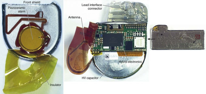
 ) have a clear plastic header, to which the leads are attached, and a titanium casing, or “can,” that houses the electronic components. The volume of the can is in the range of 10 to 15 cm3 for pacemakers and 30 to 35 cm3 for ICDs. Components common to both include the battery, voltage supply/control unit, microprocessor, ROM and RAM memory, telemetry control, system controller, rate-adaptive sensors, filters, sensing amplifier, and pacing output circuit/control unit. ICDs have additional high-voltage components, including a transformer, capacitor, and output circuitry.
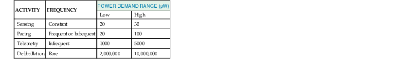
 ). ICDs often use lithium silver vanadium oxide or lithium manganese dioxide batteries. Batteries have an energy density exceeding 3000 J/cm.3
Pacing Modes, Timing Cycles, Blanking, and Refractory Periods
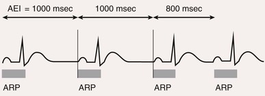
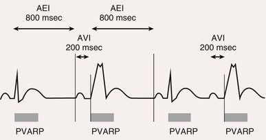
Pacing Modes
 ).
).
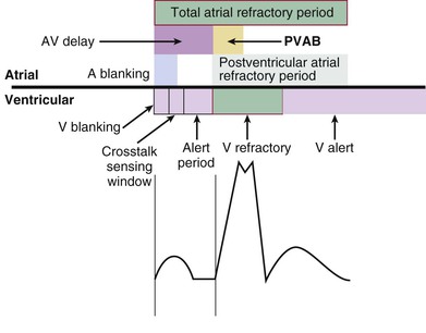
Blanking and Refractory Periods
Definitions
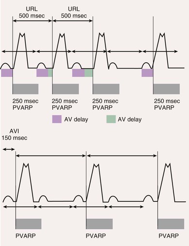
Postventricular Atrial Refractory Period
 ).
).
Rate-Adaptive Pacing
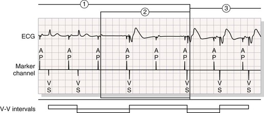
Automatic Mode Switching
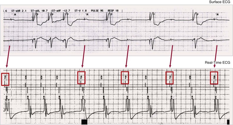
Pacing Algorithms to Avoid Unnecessary Right Ventricular Pacing
Automatic Optimization of Other Pacemaker Function Based on Sensing
 ). Safety pacing may be identified on ECGs by noting a shorter than programmed AV delay, usually 80 to 130 milliseconds. Noise reversion to fixed-rate asynchronous pacing prevents pacemaker inhibition during continuous ventricular oversensing, including that occurring during electromagnetic interference from sources such as electrocautery. Automatic assessment of the pacing capture threshold is performed by closed-loop feedback algorithms that periodically test capture and adjust the output based on test results. This feature permits use of an output that is just sufficient to achieve capture and results in safety, as well as conservation of battery energy.
Detection of Ventricular Tachycardia and Fibrillation in Implantable Cardioverter-Defibrillators
Rate, Duration, and Detection Zones
![]()
Stay updated, free articles. Join our Telegram channel

Full access? Get Clinical Tree


Pacemakers and Implantable Cardioverter-Defibrillators
36