Pacemaker Implantation
Permanent Pacemaker Implantation
Location of Implantation
Permanent pacemaker implantation can be done in the cardiac catheterization laboratory or in the operating room. Both locations have unique advantages and disadvantages. The operating room often has better lighting and thus allows better visualization of the device pocket, but fluoroscopy can be less optimal in the operating room, which generally utilizes a C-arm radiology device. Sterility was once thought to be more advantageous than the operating room setting. Data support that infection rates tend to be extremely low in both settings. Scrub technicians and assistants in the operating room are often equally matched by personnel in busy cardiac catheterization laboratories.
Regardless of the location of implantation, the operating room or the cardiac catheterization laboratory, similar personnel are required: a radiology technician, a scrub-technician/assistant, circulating personnel, and a nurse/nurse anesthetist/anesthesiologist, who is responsible for monitoring hemodynamics and the patient’s level of consciousness.
The presence of an anesthesiologist or a nurse anesthetist can be an advantage in the rare patient who needs better control of the airway during the implantation. In the majority of patients, a team experienced with conscious sedation can do an excellent job in keeping patients comfortable without the need for anesthesia support.
The circulating personnel must be competent in the use of a pacing system analyzer. In many busy implanting operating rooms/cardiac catheterization laboratories, this person is an experienced team member, who has the ability to test pacing lead impedance measurements, capture threshold measurements, and sensing measurements. Sometimes, this person is a representative of the device company, and can perform an equally acceptable job. The physician must be able to supervise and interpret the data given to him or her by the pacemaker representative or the staff person responsible for use of the pacing system analyzer.
Venous Access
Accessing a venous entry site has become quite important in any device implantation. Historically, the cephalic vein cut-down approach has set a high standard for safety and long-term lead performance (Fig. 10-1). Using this cephalic cut-down technique, the risk of pneumothorax is nil and the risk of long-term lead failure due to crush injury through the subclavius muscle/ligament is also eliminated.
A much less favorable approach to central venous entry would be the subclavian stick. Using landmarks, the subclavian vein can be approached quickly, but the speed of access has to be weighed against the increasing complication rate, particularly with pneumothorax, vascular injury, and bleeding. By performing this intrathoracic venous entry, using landmarks of the patient’s anatomy, the lead can often be pinned down from the subclavius muscle or ligament and create a friction point leading to late lead failure.
A third approach is the axillary vein approach (Fig. 10-2). The nomenclature of the subclavian vein changes when the vein exits the thorax
and passes over the first rib. From the medial border of the first rib, seen on x-ray, the vein moves laterally in the extra thoracic portion of the chest. The needle is placed into the axillary vein a few centimeters more lateral than the traditional subclavian vein approach. This approach can be performed using only surface anatomy landmarks, including the visualization of the lateral portion of the pectoralis minor muscle, the anatomy of the clavicle, and acromion process of the shoulder. A better visualization of the axillary vein can be performed if a venogram is performed during the access approach. By injecting approximately 25 cc of a low osmolar contrast dye into the IV in the patient’s forearm, the anatomy of the axillary vein can be seen as the contrast crosses the first rib. With the dye column in the axillary vein, the needle can be placed into this vein directly overlying the first rib. Generally, the needle can be visualized as it pushes down onto the surface of the first rib, directly overlying the venous column. Then by withdrawing the needle slowly, blood return into the syringe is noted and a soft guidewire can be advanced into the axillary vein, and then manipulated through the venous system to the right heart chambers. After performing this technique many times, most operators feel very comfortable using this same technique without seeing the dye column. By placing the needle directly overlying the first rib, the operator can develop a “feel” for where the vein would be if a dye column was utilized. Dye injections
can then be used only in difficult access situations. Using the dye injection approach does give some operators a higher comfort level in performing this accessed technique. This technique is also very helpful in patients who have chronic leads in place and the patency of the vein needs to be assessed prior to attempting access.
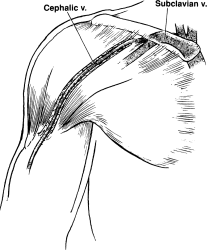 Figure 10-1 Deltopectoral Groove. The cephalic vein travels from the arm, through the deltopectoral groove, and joins the subclavian vein. It is located easily in most patients. |
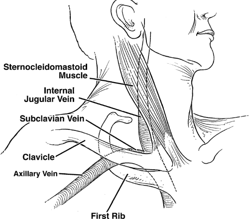 Figure 10-2 Veins in Relation to External Landmarks. Axillary, subclavian, and internal jugular veins are demonstrated in relation to external landmarks. |
With improving ultrasound equipment, accessing the axillary vein has become quite routine (Fig. 10-3). Companies provide small transducers to perform ultrasound-guided access. By placing a sterile sleeve over the ultrasound probe, visualization of the axillary vein and axillary artery can easily be performed. Color-flow Doppler adds little to the 2-D visualization. By applying gentle pressure over the vein, the vein will flatten quickly. By applying a similar amount of pressure with the transducer over the axillary artery, no change in the circular appearance of the artery is noted. The needle can be visualized as it enters the vein and partially collapses the vein. A guidewire is advanced through the needle and then by slowly withdrawing the needle,
access can be achieved with an introducer sheath (Fig. 10-4). This technique has a rapid learning curve and allows a very lateral entry point into the axillary vein. One advantage of the axillary vein approach over the cephalic vein approach is that multiple leads can easily be placed into the axillary vein. With an experienced implanter, pneumothorax can be virtually eliminated by using any of these axillary vein entry approaches. The axillary venous approach also eliminates the long-term complications of lead friction at the subclavian muscle or ligament insertion site.
access can be achieved with an introducer sheath (Fig. 10-4). This technique has a rapid learning curve and allows a very lateral entry point into the axillary vein. One advantage of the axillary vein approach over the cephalic vein approach is that multiple leads can easily be placed into the axillary vein. With an experienced implanter, pneumothorax can be virtually eliminated by using any of these axillary vein entry approaches. The axillary venous approach also eliminates the long-term complications of lead friction at the subclavian muscle or ligament insertion site.
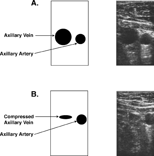 Figure 10-3 Access to the Axillary Vein. An ultrasound probe is placed within a sterile sleeve and gently introduced into the incision upon the pectoralis fascia, close to the deltopectoral groove. No pressure is applied in A. InB, light downward pressure is applied compressing the vein, but having no effect on the shape of the artery. Using a platinum-coated micropuncture needle, the ultrasound images can show the needle advance into the vein safely. |
One slight disadvantage of axillary vein approach is back bleeding. When the lead is smaller than the peel-away sheath diameter, particularly when it is a difference of more than two French sizes, back bleeding can be a challenge. When venous pressure is elevated in a patient with congestive heart failure, this can be a particularly noticeable problem. A purse string suture with absorbable suture usually eliminates this problem, even when multiple leads are utilized. By making separate sticks for each lead introduced, this back bleeding problem is usually minimal. When a single access site is used for multiple leads, back bleeding can be a more significant problem and the purse string suture technique is usually required.
The ideal combination of a cephalic cut-down technique and the axillary vein technique allows the operator to have the best of both techniques available, particularly when multiple leads need to be placed. The subclavian vein approach, despite its speed advantage, should be avoided.
Lead Placement
After gaining access, fluoroscopic imaging is utilized to guide the lead to the desired site of pacing. Several small studies have shown that site-specific pacing may be advantageous. Site-specific pacing generally requires an active fixation lead. The alternative approach is to use a passive fixation lead. The passive fixation lead approach does limit the implanter in utilizing classic sites of lead implantation: the right atrial appendage for the atrial approach and the right ventricular apex for the ventricular approach.
Active fixation leads and passive fixation leads (tined leads) are the two types available for the transvenous approach and both have their pros and cons. The active leads typically have a helix, which penetrates the endocardium and “grasps” the cardiac muscle. The helix can be exposed or can be part of a mechanism which protrudes from inside the lead out, using a lead mechanism that can extend or retract the helix into the myocardium. One of the major advantages of an active fixation lead is that the lead can be isodiametric. This means that the lead would have the same diameter from the very tip of the lead all the way back through the body of the lead. The reason this is important is that if the lead would ever need to be extracted, the extraction process would be much easier than a lead that was not isodiametric.
In the past, the active fixation lead had greater inflammation of the tip, leading to poorer acute and chronic thresholds. This potential disadvantage
has been eliminated with the use of steroid eluding tips. Chronic thresholds are no longer a significant factor in the decision regarding active versus passive fixation.
has been eliminated with the use of steroid eluding tips. Chronic thresholds are no longer a significant factor in the decision regarding active versus passive fixation.
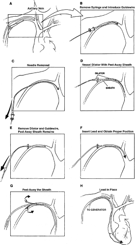 Figure 10-4 Axillary Stick Technique with Peel-away Sheath. Axillary stick technique with peel-away sheath. A needle is placed into the axillary vein (see text for proper positioning), and a guidewire is advanced through the needle into the axillary vein and superior vena cava. The needle is removed, and a dilator with a peel-away sheath around it is advanced through the skin into the vein. The guidewire and dilator then are removed, leaving the peel-away sheath in place. A lead or leads can be advanced through the sheath and placed in the proper position. The advantage of the peel-away sheath is that it can be removed, peeled in half, and discarded. The pacemaker lead then is attached to the generator subcutaneously and the skin is closed. |
An active fixation lead does make extraction easier, but a disadvantage of an active fixation lead is a higher perforation risk at the time of implantation. Passive fixation leads can cause perforation, but this is less likely. The “tines” that help fixate the lead to the right atrial appendage, endocardium, or the right ventricular endocardium can make extraction challenging due to the ingrowth of fibrous material at this site in the lead.
Mapping is not very useful with passive fixation leads when compared to active fixation leads. Passive fixation leads placed into the right atrial appendage can allow far field R wave sensing. This causes oversensing, which is a significant disadvantage and should be avoided if possible. Many operators feel that using active fixation leads can allow a patient to be mobilized earlier than when passive leads are used. This has not been well studied.
Tined or passive leads are typically anatomy dependent. Sometimes, placing the tined leads across the tricuspid valve can be challenging due to the leads “grasping” parts of the tricuspid valvular structure with the tined tips. Some tined leads have very high impedance measurements, a long-term advantage of which is battery longevity (see Chapter 2).
In summary, both tined leads (passive fixation) and active fixation leads have advantages and disadvantages. The active fixation is more commonly used.
Site-specific pacing enthusiasts can demonstrate that capturing specific areas of the right ventricle or right atrium can allow more rapid activation of the atria or ventricles. This can be particularly demonstrated if the His bundle is captured, utilizing site-specific pacing in the high right ventricular septum. This particular advantage of active fixation leads may be shown to have specific clinical advantages in the future.
Pacing System Analyzer
Satisfactory lead performance can be assessed by using a pacing system analyzer. The minimum voltage necessary to capture the right ventricle is usually
less than 1 V a preferably less than 0.5 V. This voltage capture threshold is typically assessed utilizing a pulse width set arbitrarily at 0.5 msec. The pacing impedance measurement in ohms should be calculated with the pacing system analyzer. A stable impedance generally implies a good site of fixation with the distal tip of the lead. When the impedance varies significantly, this may imply “micro-dislodgement.” The patient’s intrinsically generated QRS pattern is also measured. This measurement of sensing allows the pacemaker to inhibit voltage output when voltage output is not needed. The amplitude of the signal should be of sufficient size. Utilizing a 5 mV R wave when assessing ventricular sensing is usually the minimum required R wave. When R waves are smaller than 5 mV, oversensing T waves and undersensing R waves can become a problem.
less than 1 V a preferably less than 0.5 V. This voltage capture threshold is typically assessed utilizing a pulse width set arbitrarily at 0.5 msec. The pacing impedance measurement in ohms should be calculated with the pacing system analyzer. A stable impedance generally implies a good site of fixation with the distal tip of the lead. When the impedance varies significantly, this may imply “micro-dislodgement.” The patient’s intrinsically generated QRS pattern is also measured. This measurement of sensing allows the pacemaker to inhibit voltage output when voltage output is not needed. The amplitude of the signal should be of sufficient size. Utilizing a 5 mV R wave when assessing ventricular sensing is usually the minimum required R wave. When R waves are smaller than 5 mV, oversensing T waves and undersensing R waves can become a problem.
Sensing and capture thresholds in the atrium are different. The atrial capture threshold should be less than 1.5 V at 0.5 msec. Some active-fixation atrial leads will show a transiently higher threshold of 2 V at 0.5 msec due to acute injury. This usually drops in 10 to 30 minutes if followed closely without moving the lead. Preferably, when the capture threshold is less than 1 V long-term lead performance is generally acceptable. The sensed P wave should be greater than 1.5 mV and should not include oversensing of a far field R wave.
When testing the atrial lead, the method used to document atrial capture can be variable. Using the surface electrocardiogram recording equipment in the laboratory, a P wave can be visualized after the pacemaker spike. With bipolar pacemaker leads, the spike can be very small and difficult to see. The presence of a QRS complex occurring regularly after each atrial spike can be used to assess atrial capture. This technique is not useful in a patient with variable conduction across the AV node or in patients who have atrial ventricular heart block. Using fluoroscopy to see atrial movement during capture is an unreliable way to document capture.
The peel-away sheath used to implant both atrial and ventricular pacemaker leads is generally sized to allow freedom of movement of the lead within the sheath. A sheath that also includes a hemostatic valve at the end can help prevent inadvertent air embolism or back bleeding during the implantation procedure. Patients with relatively low venous pressure or patients with sleep apnea, who suddenly inspire deeply, can have significant amounts of air inspired through peel-away sheaths where the hemostatic valve is not in place. If a hemostatic valve is not in place in a peel-away sheath, the lead should be placed quickly into the peel-away sheath immediately after entering the vein.
After a guidewire is placed into the desired venous structure and fluoroscopically manipulated to the right heart, the peel-away sheath is advanced over a straight dilator over the guidewire and the dilator and guidewire are quickly removed.
After the lead has been placed in the right ventricle or right atrium, experience will dictate how much extra lead should be placed into the venous
system to allow “slack” so that the lead will not dislodge when the patient stands or takes a deep breath. Too much straightening of the lead when someone inspires would indicate not enough lead slack. On the other hand, too much lead slack can lead to problems with prolapse of the lead into the right ventricle or inferior vena cava.
system to allow “slack” so that the lead will not dislodge when the patient stands or takes a deep breath. Too much straightening of the lead when someone inspires would indicate not enough lead slack. On the other hand, too much lead slack can lead to problems with prolapse of the lead into the right ventricle or inferior vena cava.
Once the lead is in place and sensing and capture threshold and pacing impedance measurements are found to be acceptable, the lead needs to be secured to the pectoralis fascia. A nonabsorbable suture is attached to the pectoralis fascia and a loop from the suture is then placed over the lead collar, close to the entry site. Care must be taken not to apply too much tension over the lead collar as this can cause chronic lead injury due to disruption of insulation or to the conductor itself. Suture sleeves help prevent problems with too much tension. Alternatively, too little pressure over the lead collar can let the lead slip and cause early lead dislodgement.
Cardiac Resynchronization Lateral Wall Lead Placement
Left ventricular epicardial pacing can be achieved through placement of a lead into the coronary sinus, and then placing the lead out into a lateral vein off of the coronary sinus, onto the surface of the left ventricular epicardium. This approach is utilized in patients who have significant intraventricular conduction block and may benefit clinically with cardiac resynchronization. Placing the left ventricular epicardial lead in this way obviates the need for a surgical approach in placement of a lead directly onto the left ventricular epicardium. Newer techniques and experience have shown that the overwhelming majority of patients can have leads placed transvenously onto the left ventricular epicardium.
Placement of a left ventricular epicardial lead in this way requires three steps. The first step is to access the coronary sinus with a coronary sinus guide. This access can be achieved by using the right anterior oblique view of the AV annulus. By placing the coronary sinus sheath past the tricuspid valve, and then withdrawing it to the right atrium while providing counterclockwise torque, the coronary sinus can generally be entered. In patients with severe cardiomyopathy, particularly when they have longstanding atrial fibrillation, this technique is not as helpful and may require using different types of internal catheters and guidewires to access the coronary sinus.
Once the coronary sinus is engaged with the coronary sinus guide, it is highly recommended that venography be performed. Using a balloon occlusive angiographic catheter, the coronary sinus is visualized, using retrograde injection of a 50/50 mixture of a low osmolar iodine contrast medium and saline. It is helpful to inflate the balloon to obstruct coronary sinus flow at the same time fluoroscopy is performed. Digital recording of the venography in the RAO view and LAO view allows visualization of the lateral branches. The ideal location for epicardial pacing is generally in the lateral left ventricular epicardium. When the left ventricle is viewed in the LAO view, the 2 o’clock to 4 o’clock ventricular epicardial area should be the target for biventricular pacing.
The second step is to analyze the lateral veins for the best placement to provide long-term lead stability and excellent pacing of the lateral left ventricular epicardium. The third step is, lead placement techniques that use lateral vein introducers for direct lead delivery are being developed. In addition, some coronary sinus guides have very flexible tips which allow subselected entry into the desired lateral vein. Having experience and knowledge of several techniques can aid in more challenging cases.
Stay updated, free articles. Join our Telegram channel

Full access? Get Clinical Tree


