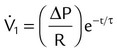
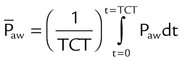
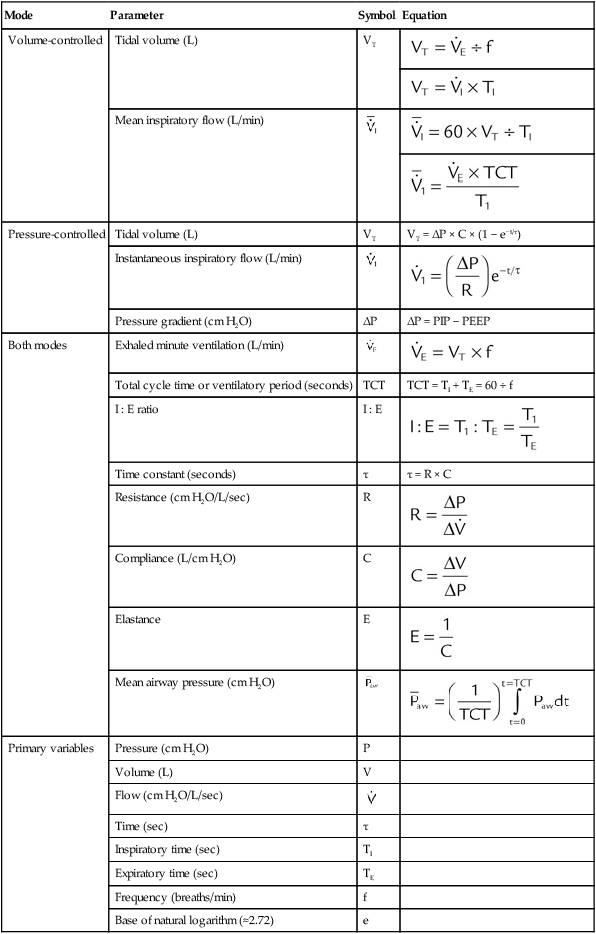
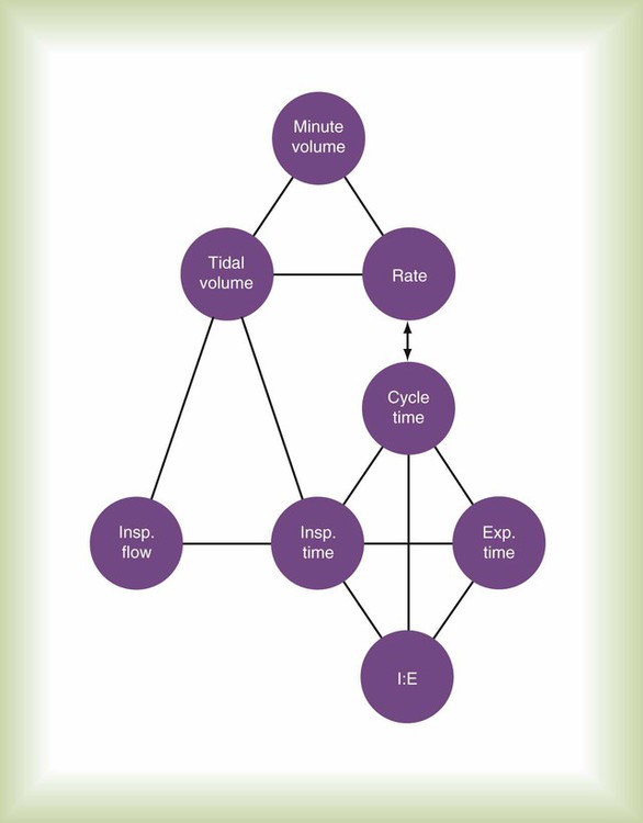
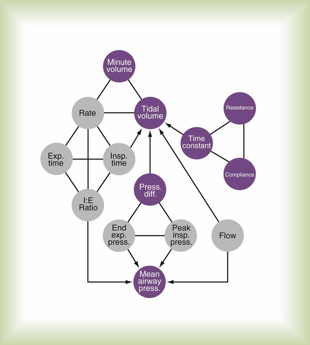
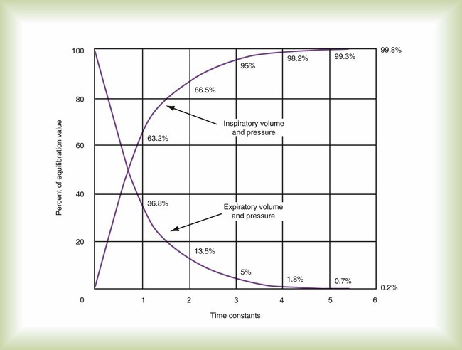
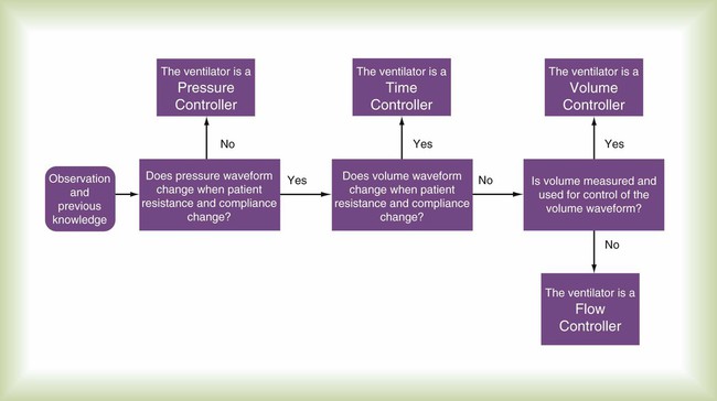
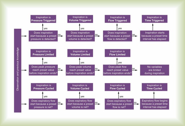
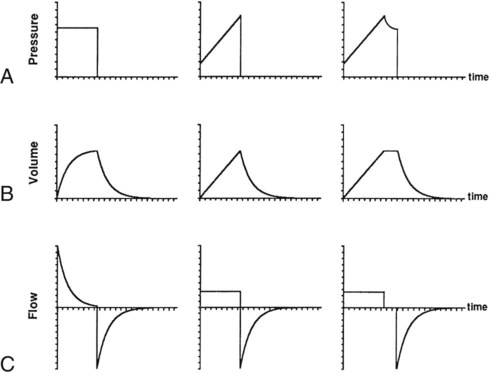
After reading this chapter you will be able to: To initiate and manage a mechanical ventilator safely and effectively, the respiratory therapist (RT) must thoroughly understand (1) ventilator design, classification, and operation; (2) appropriate clinical application of ventilatory modes (i.e., the proper matching of ventilator capability with physiologic need); and (3) the physiologic effects of mechanical ventilation, including gas exchange and pulmonary mechanics. This chapter focuses on the first and second of these. This chapter explains classification terminology and outlines a framework for understanding current and future ventilatory support devices.1–3 For the application of ventilators, the specific indications and clinical use of the various modes of full and partial ventilatory support are outlined. To understand how ventilators work, one must have some knowledge of basic mechanics. A ventilator is simply a machine, which is a system designed to alter, transmit, and direct applied energy in a predetermined manner to perform useful work.4 Ventilators are provided with energy in the form of either electricity or compressed gas. The energy is transmitted or transformed (by the drive mechanism of the ventilator) in a predetermined manner (by the control circuit) to augment or replace the patient’s muscles in performing the work of breathing (the desired output). To understand mechanical ventilators, the following four basic functions of ventilators must be understood: The drive mechanism of the ventilator converts the input power to useful work. The characteristic flow and pressure patterns the ventilator produces are determined in part by the type of drive mechanism it contains. Drive mechanisms can be either (1) a direct application of compressed gas via a pressure-reducing valve or (2) an indirect application via an electrical motor or compressor. Descriptions of these devices are provided in textbooks devoted to respiratory care equipment.6 The output control valve regulates the flow of gas to the patient. It may be a simple on/off exhalation valve, as in the Newport E100i (Newport NMI Ventilators; Newport Medical Instruments, Newport Beach, CA). Alternatively, the output control valve can shape the output waveform, as in the Maquet SERVO-i (Maquet, Bridgewater, NJ). Commonly used output control valves include the pneumatic diaphragm, electromagnetic poppet/plunger valve, and proportional valve.6 Knowledge of the mechanics of breathing provides a good foundation for understanding how ventilators work. Specifically, the pressure needed to drive gas into the airway and inflate the lungs is important. The formula that relates these variables is known as the equation of motion for the respiratory system (Figure 42-1):7 Pressure, volume, and flow all are changeable variables measured relative to their baseline or end expiratory values. When pressure, volume, and flow are plotted as functions of time, characteristic waveforms for volume-controlled ventilation and pressure-controlled ventilation are produced (Figure 42-2). The conventional order of presentation is pressure, volume, and flow from top to bottom. Convention also dictates that positive flow values (above the horizontal axis) correspond to inspiration and that negative flow values (below the horizontal axis) correspond to expiration. The vertical axes are in units of the measured variables (usually cm H2O for pressure, L or ml for volume, and L/min or L/sec for flow). The horizontal axis of these graphs is time. Many ventilators have monitors that display pressure, volume, and flow waveforms, providing the clinician with information to evaluate ventilator-patient interaction. Figure 42-2 shows that the expiratory lung pressure curves are the same shape for both volume and pressure control. This shape is called an exponential decay waveform (often called a decelerating waveform), and it is characteristic of passive emptying of the lungs (exhalation). Solving the equation of motion for lung pressure (assuming no auto-PEEP) provides the following expression: This expression shows that after an expiratory time equal to one time constant, only 37% of the lung pressure is left. Because volume is equal to pressure multiplied by compliance, multiplication of both sides of Equation 42-3 by compliance shows that only 37% of the tidal volume remains in the lungs. The implication is that 63% of the tidal volume has been exhaled. After two time constants (i.e., t = 2RC), exhalation is 86% completed, and after three time constants, exhalation is 95% complete. After five time constants, exhalation is considered to be 100% complete for practical purposes (Figure 42-3). A similar expression can be derived for passive inhalation: When this equation is graphed, it looks like the curved line showing lung pressure and volume during inhalation for pressure-controlled ventilation in Figure 42-2. These same equations govern the passive flow curves for volume-controlled and pressure-controlled ventilation. It is important to understand the concept of time constants to make appropriate ventilator setting adjustments. In any mode of ventilation, the expiratory time should be at least three time constants long to avoid clinically important gas trapping. Similarly, in pressure-controlled modes, inspiratory time (for passive inspiration) should be at least five time constants long to get the maximum tidal volume from the set pressure gradient (i.e., peak inspiratory pressure [PIP] − end expiratory pressure). Mechanical control circuits use devices such as levers, pulleys, and cams. These types of circuits were used in the early manually operated ventilators illustrated in history books.8 Pneumatic control is provided using gas-powered pressure regulators, needle valves, jet entrainment devices, and balloon-valves. Some transport ventilators use pneumatic control systems. Fluidic logic-controlled ventilators, such as the Bio-Med MVP-10 (Bio-Med Devices, Stanford, Connecticut) and Sechrist IV-100B (Sechrist, Anaheim, California), also use pressurized gas to regulate the parameters of ventilation. However, instead of simple pressurized valves and timers, these ventilators use fluidic logic circuits that function similar to electrical circuit boards.9 Fluidic control mechanisms have no moving parts. In addition, fluidic circuits are immune to failure from surrounding electromagnetic interference, as can occur around MRI equipment. A control variable is the primary variable that the ventilator manipulates to cause inspiration. There are only three explicit variables in the equation of motion that a ventilator can control: pressure, volume, and flow. Because only one of these variables can be the independent variable, the others are dependent variables. In other words, only one variable can be directly controlled at a time, and a ventilator must function as a pressure, volume, or flow controller. Time is implicit in the equation of motion and in some cases serves as a control variable. Figure 42-4 illustrates the criteria for determining what variable the ventilator controls at any given time. Figure 42-5 illustrates the important variables for volume-controlled modes. It shows that the primary variable we wish to control is the patient’s minute ventilation. A particular ventilator may allow the operator to set minute ventilation directly. More frequently, minute ventilation is adjusted by means of a set tidal volume and frequency. Tidal volume is a function of the set inspiratory flow and the set inspiratory time. Inspiratory time is affected by the set frequency and, if applicable, the set inspiratory-to-expiratory (I : E) ratio. The mathematical relationships among all these variables are shown in Table 42-1. TABLE 42-1 With pressure-controlled modes, the goal is also to maintain adequate minute ventilation. However (as the equation of motion shows), when pressure is controlled, tidal volume and minute ventilation are determined not only by the ventilator’s pressure settings but also by the elastance and resistance of the patient’s respiratory system. This additional variable makes minute ventilation (and gas exchange) less stable in pressure-controlled modes than in volume-controlled modes. Figure 42-6 shows the important variables for pressure-controlled modes. Tidal volume is not set on the ventilator. It is the result of the pressure settings and the patient’s lung mechanics and the inspiratory time. On some ventilators, the speed with which the PIP is achieved (i.e., the pressure rise time) is adjustable. That adjustment affects the shape of the pressure waveform and the mean airway pressure. Mean airway pressure is important because, within reasonable limits, as the mean airway pressure increases, arterial O2 tension increases. Mean airway pressure is higher for pressure-controlled modes than for volume-controlled modes (at the same tidal volume) owing to the differences in the shapes of the airway pressure waveforms. The phase variable is a variable that is measured and used by the ventilator to initiate some phase of the breath cycle. The variable causing a breath to begin is the trigger variable. The variable limiting the magnitude of any parameter during inspiration is the target variable. The variable causing a breath to end is the cycle variable. To describe what happens during expiration, the baseline variable that is in effect must be known. Figure 42-7 shows the criteria for determining phase variables. Compared with pressure, using flow as the trigger variable decreases a patient’s work of breathing.11,12 However, ventilators that use a flow-triggering mechanism tend to be highly susceptible to circuit leaks or movement caused by turbulence or gas flow through condensed water. Either of these conditions can cause spurious breaths, which can disrupt patient-ventilatory synchrony and increase the work of breathing. The perception exists, with regard to the most recent generation of ICU ventilators, that pressure and flow triggering are equally effective. Using volume as the trigger can help overcome synchrony problems caused by circuit leaks, but at the present time only the Draeger Babylog (Draeger Medical, Telford, Pennsylvania) uses true volume triggering. Mini Clini Calculate the Expiratory Time Setting from the Frequency and Inspiratory Time Clinicians often confuse target variables with cycle variables. A cycle variable always ends inspiration. A target variable does not terminate inspiration—it sets an upper bound only for pressure, volume, or flow. Figure 42-8 illustrates the importance of distinguishing between target and cycle variables. When a ventilator is set to flow cycle, it delivers flow until a preset level is met, and then flow stops and expiration begins. The most frequent application of flow cycling is in the pressure support mode. In this mode, the control variable is pressure, and the ventilator provides the flow necessary to meet the inspiratory pressure limit. In doing so, flow starts out at a relatively high value and decays exponentially (see Figure 42-2). When flow has decreased to a relatively low value (e.g., 25% of peak flow, preset by the manufacturer), inspiration is cycled off. Manufacturers often set the cycle threshold slightly above zero flow to avoid inspiratory times from getting so long that patient synchrony is degraded. Mini Clini Calculate Inspiratory Hold Time Given Set Inspiratory Time, Tidal Volume, and Flow When Using the Siemens Servo 1. Calculate the inspiratory flow time (TIF) using appropriate unit conversions: 2. Compare the set inspiratory time (0.8 second) with the flow time resulting from the tidal volume and flow settings (0.5 second). Inspiratory time lasts longer than inspiratory flow. Because inspiration is time cycled, this means that there is an inspiratory hold of duration equal to 0.8 − 0.5 = 0.3 second. 3. You could eliminate the inspiratory hold either by decreasing the inspiratory flow or by decreasing the inspiratory time. The goal is to minimize the mean inspiratory pressure. You choose to decrease inspiratory time for two reasons: (1) It decreases the I : E ratio and may allow more time for spontaneous breaths to occur, lowering mean intrathoracic pressure; (2) decreasing inspiratory flow may make tidal volume delivery slower than the patient demands, decreasing patient-ventilator synchrony.
Mechanical Ventilators
 Discuss the basic design features of ventilators.
 Classify ventilators and describe how they work.
 Define what constitutes a mode of ventilation.
 Classify and discuss modes of ventilation.
How Ventilators Work
Power Transmission and Conversion
Drive Mechanism
Output Control Valve
Control System
 Equation 42-1, A
 Equation 42-2
 Equation 42-3
 Equation 42-4
Control Circuit
Control Variables
Mode
Parameter
Symbol
Equation
Volume-controlled
Tidal volume (L)
VT


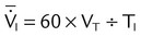
Mean inspiratory flow (L/min)

Pressure-controlled
Tidal volume (L)
VT
VT = ΔP × C × (1 − e−t/τ)
Instantaneous inspiratory flow (L/min)

Pressure gradient (cm H2O)
ΔP
ΔP = PIP − PEEP
Both modes
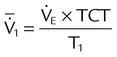
Exhaled minute ventilation (L/min)


Total cycle time or ventilatory period (seconds)
TCT
TCT = TI + TE = 60 ÷ f
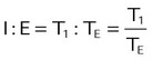
I : E ratio
I : E
Time constant (seconds)
τ
τ = R × C
Resistance (cm H2O/L/sec)
R

Compliance (L/cm H2O)
C

Elastance
E

Mean airway pressure (cm H2O)

Primary variables
Pressure (cm H2O)
P
Volume (L)
V
Flow (cm H2O/L/sec)

Time (sec)
τ
Inspiratory time (sec)
TI
Expiratory time (sec)
TE
Frequency (breaths/min)
f
Base of natural logarithm (≈2.72)
e
Phase Variables
Trigger Variable
Flow Triggering
Flow Trigger Variable
Other Trigger Variables
Target Variable
Cycle Variable
Flow Cycling
Time Cycling

 Rule of Thumb
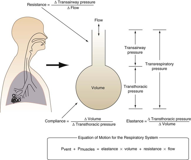
 is flow (usually zero unless auto-PEEP is present). Auto-PEEP is the difference between end expiratory airway pressure and end expiratory lung pressure. The combined muscle and ventilator pressures cause gas to flow into the lungs. Elastance (elastance = Δpressure/Δvolume) and resistance (resistance = Δpressure/Δflow) together constitute the impedance or load against which the muscles and ventilator do work. The equation of motion is sometimes expressed in terms of compliance (compliance = Δvolume/Δpressure) instead of elastance.
 are constant because of the preset values of tidal volume and inspiratory flow, as auto-PEEP increases, peak inspiratory pressure increases. For pressure control ventilation, the airway pressure waveform is constant because of the preset value of inspiratory pressure. As auto-PEEP increases, both inspired tidal volume and peak inspiratory flow decrease. If inspiration is unassisted (PVENT = 0), the equation shows that PMUS must exceed auto-PEEP before inspiratory flow can begin. If the patient is connected to a ventilator, P
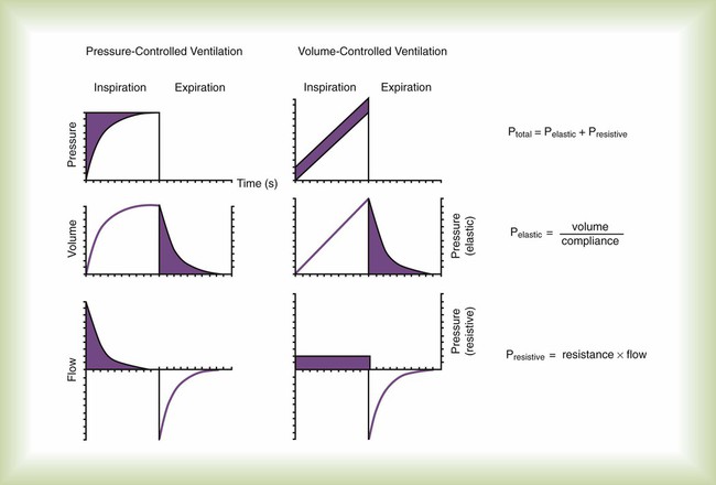
 Problem

 Problem