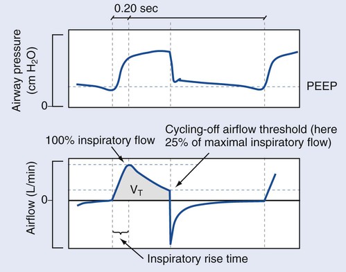
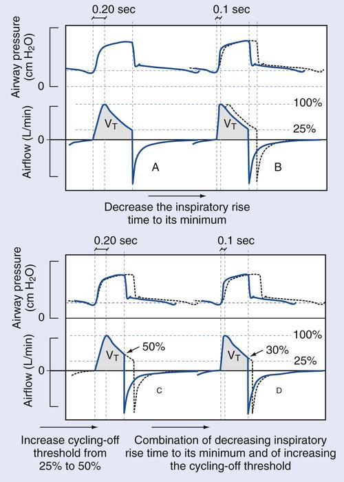
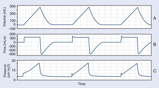
1. Prepare a mechanical ventilator for use. 2. Place the ventilator in the various modes of ventilation. 1. Clean the exterior surface of the ventilator according to the manufacturer’s specifications. 2. Attach the appropriate inspiratory and expiratory filters. 3. Attach a clean ventilator tubing circuit to the ventilator. 4. Connect the ventilator to compressed oxygen and air outlets. 5. Plug the ventilator into the appropriate electrical outlet. 1. Establish that all pressure tests have been completed successfully. 2. Establish that all flow tests have been completed successfully. 3. Establish that all volume tests have been completed successfully. 4. Establish that all tubing compliance tests have been completed successfully. 5. Establish that all oxygen sensor tests have been completed successfully 6. Establish that all leak tests have been completed successfully. Continuous positive airway pressure (CPAP) is a spontaneous mode of ventilation. In this mode, the RT sets a pressure level that is maintained by the ventilator throughout breathing, and the patient’s tidal volume and respiratory rate are totally dependent on his or her effort. Therefore, the baseline on the pressure-time scalar graphic will be above atmospheric pressure. The baseline pressure is raised to cause an increase in the patient’s functional residual capacity (FRC). It should look similar to the graphics in Figure 20-1, which shows an illustrations of eight breaths. At the beginning of each breath on the graphic, a slight drop in pressure is seen. This is the patient’s inspiratory effort. The pressures during this mode ideally will fluctuate plus or minus 2 or 3 cm H2O in relation to the set baseline pressure. Pressure support ventilation (PSV) is often used in conjunction with CPAP and provides assistance to a spontaneous breath. A pressure support (PS) level is set by the RT, and once the patient’s inspiratory effort surpasses the trigger threshold, the PS is delivered. Parameters that the RT may adjust in PSV are the PS level, the trigger sensitivity threshold, the inspiratory rise time, and, occasionally, the terminal flow value. As in CPAP, the patient in PSV can initiate a breath as often as desired, and the PS breath will augment the patient’s inspiratory effort. This is illustrated in Figure 20-2. The breath is controlled by the patient, and inspiration ends or cycles off as a result of terminal inspiratory flow. The terminal inspiratory flow is set to an amount based on a percentage of the patient’s peak inspiratory flow. Some ventilators have a fixed value of 25% of the patient’s peak inspiratory flow. In addition, some ventilators will allow the operator to adjust the percent of terminal inspiratory flow to higher or lower values, depending on the patient’s needs. The changes in the parameters of a PSV are illustrated in Figure 20-3. A PS breath results in a descending flow pattern. Volume control ventilation is a mandatory mode, in which the tidal volume and flow rate remain constant breath to breath, and the airway pressure applied varies, depending on the patient’s airway resistance and lung thorax compliance. This mode is represented in the scalar graphic in Figure 20-4. For the graphic “A,” the tidal volume peaks at 0.5 liters (L) and does not vary. For the graphic “B,” the peak flow is 400 liters per second (L/s) and does not vary. This inspiratory flow time wave form is most often described as square. The inspiratory time (I-time) is 1.3 seconds and does not vary. Graphic “C” reflects a peak airway pressure of 25 cmH2O. This wave form is described as exponential, accelerating, or a shark-fin pattern. Remember that volume and flow will not vary, causing an increase in peak airway pressure, if the patient’s airway resistance increases, lung compliance decreases, or both. Conversely, the peak airway pressure will decrease if the patient’s airway resistance decreases or lung compliance increases. During volume control, the base line pressure may be increased, which will, in turn, increase the patient’s FRC. This effect may be seen on graphic “C.” At the end of each breath, the baseline pressure is held to 5 cmH2O. This indicates the amount of PEEP set. In assist control–volume control–ventilation (AC/VC), a minimum respiratory rate is set on the ventilator, but the patient can initiate and receive more than that set rate. This is done by patient effort reaching the trigger sensitivity. Each subsequent breath will be the set mandatory breath, as in the example on the scalar graphic in Figure 20-4, and each and every tidal volume will be 0.5 L. Pressure control ventilation is a mandatory mode, in which the amount of pressure applied during each breath is controlled and does not vary with patient characteristics (see Figure 20-5). As a result, the patient’s tidal volume and peak inspiratory flow rate vary, depending on airway resistance, lung compliance, or both. During this mode, if the patient airway resistance increases or lung compliance decreases, the tidal volume the patient receives decreases. The peak inspiratory pressure (PIP) is considered to be constant during inspiration and is described as a square wave form. This is shown on the pressure-time scalar graphic “C” in Figure 20-5. The flow pattern is described as descending and is illustrated on the scalar graphic “B” in Figure 20-5. As in the other modes, PEEP may be added. The amount of PEEP illustrated in Figure 20-5 is 5 cm H2O. During this mode, the operator sets the PIP, respiratory rate, I-time, fractional inspired oxygen FiO2
Mechanical Ventilators
» Skill Check Lists
20-1 Preparing a Mechanical Ventilator for Use
Procedural Preparation
Evaluation of Procedure
20-2 Wave Form Analysis
Spontaneous Modes
Continuous Positive Airway Pressure

Pressure Support Ventilation


Controlled Modes
Volume Control
Pressure Control Ventilation
![]()
Stay updated, free articles. Join our Telegram channel

Full access? Get Clinical Tree


